Introduction
Fractured-vuggy media are widely developed in carbonate rock, buried hill metamorphic rock, volcanic rock and sandy conglomerate reservoirs[1,2,3,4]. Permian Xiazijie Formation of H reservoir in Xinjiang Oilfield is a typical sandy conglomerate fractured-vuggy reservoir. Its reservoir space includes dissolution vugs, vugs, and micro-fractures[4]. Cements and fracture fillings are dominated by zeolite and calcite[4,5,6,7]. Because zeolite has large specific surface area and strong adsorption[8,9], and would reduce in permeability after absorbing water[10], since waterflooding isn’t a good choice for this reservoir, nitrogen assisted gravity drainage (NAGD) was tested for high- efficient development. However, as the fractured-vuggy media and sandstone porous media differ widely, so do their gas flooding mechanism and production performances. At present, there are few relevant researches, and thus little understanding on their oil displacement mechanism and production performance, hard to guide the compilation and implementation of gas flooding development in such reservoirs. For this reason, a visual model of fractured-vuggy reservoir was designed and manufactured. Then, NAGD experiments were carried out under the conditions of different heterogeneity, injection- production rates, and well types to find out development performance and the formation and distribution of remaining oil under different conditions. Finally, reasonable suggestions were put forward and provide technical support for the gas injection development plan in fractured-vuggy reservoirs.
1. Characteristics of storage space in fractured-vuggy reservoir
Statistics on pore types of 96 pieces of core from H reservoir of Xinjiang Oilfield show that the reservoir space is dominated by dissolution vugs and fractures (Fig. 1), which account for 78% and 19.6% of the total reservoir space respectively, and coexist with each other in band distribution (Fig. 2). Fractures are widespread and stable in the whole area, and dominated by oblique and reticular fractures[4,5], followed by high-angle and vertical fractures (Fig. 3). Fractures of 1-5 mm wide take up the largest proportion, followed by those of 0.1-1.0 mm wide.
Fig. 1.
Fig. 1.
Core slices of Well A.
Fig. 2.
Fig. 2.
Cores from Well B.
Fig. 3.
Fig. 3.
Fractures of cores from H reservoir in Xinjiang Oilfield.
2. Design of NAGD experiments
2.1. Design and manufacture of visual experiment models
In fractured-vuggy reservoirs, fractures are the main flow channels and vugs are the main reservoir space. The vugs are connected by oblique, reticular, or high-angle fractures. Under the action of dissolution and filling, the reservoir is highly heterogeneous. In order to reflect the storage space distribution and strong heterogeneity in such reservoirs, three fractured-vuggy media models were designed, and the specific parameters are shown in Table 1. (1) Model I: Same fracture aperture, but different vug sizes (Fig. 4a). (2) Model II: Different and larger fracture apertures, and different vug sizes (Fig. 4b). (3) Model Ⅲ: Different and smaller fracture apertures and different vug sizes (Fig. 4c). The fractures in Models II and III have the same heterogeneity degree with the aperture ratio of 4:3:2. In addition, the fracture-vug connection, connectivity degree, and well-vug-fracture configuration were also considered. The visual glass modelsof 25 cm × 25 cm were made according to the fractured-vuggy media models (Fig. 5). There are 4 inlets and outlets, which are numbered as No. 1 (Injector), No. 2 (Producer or injector), No. 3 (Producer), and No. 4 (Producer) respectively. The models were made by single glass etching, and two glass plates were strongly bonded to ensure internal sealing.
Table 1 Parameters of vug size and fracture aperture in the models.
| Model | Fracture aperture/mm | Vug diameter/mm | Fracture and vug depth/mm | Pore volume/ mL | ||||
|---|---|---|---|---|---|---|---|---|
| Big | Medium | Small | Big | Medium | Small | |||
| Model Ⅰ | 1.0 | 15.0 | 10.0 | 5.0 | 3.5 | 21.5 | ||
| Model Ⅱ | 2.0 | 1.5 | 1.0 | 15.0 | 10.0 | 5.0 | 3.5 | 24.0 |
| Model Ⅲ | 1.2 | 0.9 | 0.6 | 15.0 | 10.0 | 5.0 | 2.5 | 15.0 |
Fig. 4.
Fig. 4.
Schematic diagrams of fractured-vuggy media models.
Fig. 5.
Fig. 5.
Experimental model of fractured-vuggy media.
2.2. Experimental contents and procedures
NAGD experiments on these models were carried out to study the development performance and formation and distribution of remaining oil under different fracture heterogeneity, vertical injector-producer relations, gas injection rates, and horizontal well injection-production conditions. The experimental contents are listed in Table 2.
Table 2 Number and contents of experiments.
| Serial No. | Experiment content | Model placement | |
|---|---|---|---|
| ①-a | Different heterogeneity experiments | Model I, gas injection at the top and production from the whole-interval | Placed vertically as shown in |
| ①-b | Model I, gas injection at the top and production from the bottom | Placed vertically as shown in | |
| ①-c | Model II, gas injection at the top and production from the whole-interval | Placed vertically as shown in | |
| ①-d | Model II, gas injection at the top and production from the bottom | Placed vertically as shown in | |
| ①-e | Model III, gas injection at the top and production from the whole-interval | Placed vertically as shown in | |
| ①-f | Model III, gas injection at the top and production from the bottom | Placed vertically as shown in | |
| ②-a | Experiments on different injection rates | Model I, Q=3 mL/min | Placed vertically as shown in |
| ②-b | Model I, Q=5 mL/min | Placed vertically as shown in | |
| ②-c | Model III, Q=3 mL/min | Placed vertically as shown in | |
| ②-d | Model III, Q=5 mL/min | Placed vertically as shown in | |
| ③-a | Horizontal well injection and production experiments | Model I | Rotated 90° anticlockwise as shown in |
| ③-b | Model III | Rotated 90° anticlockwise as shown in | |
| ④ | Plane displacement experiment | Placed horizontally as shown in | |
Experimental procedure of top gas injection and whole- interval production: (1) The model was placed vertically as shown in Fig. 5. The model was first saturated with oil after cleaning and vacuumizing, then, the total volume, fracture and vug volumes were calculated. (2) Gas was injected in Well No. 1 at a rate of 1 mL/min, while Wells No. 2 and No. 4 were opened to produce at the same time. (3) The producer was shut in after complete gas channeling, while the remaining wells continued to produce until complete gas channeling. The oil production of each well was measured and the recovery at different stages was calculated.
Experimental procedures of top gas injection and production from the bottom: (1) The model was placed vertically as shown in Fig. 5, it was cleaned and vacuumized firstly, then, re-saturated with crude oil; (2) Gas was injected in wells No. 1 and No. 2 at a rate of 1 mL/min, while Wells No. 3 and No. 4 were producing; (3) The producer was shut in after complete gas channeling, while the remaining wells continued to produce until complete gas channeling. The oil production of each well was measured and the recovery at different stages was calculated.
Experimental procedures for different gas injection rates: (1) The model was placed vertically as shown in Fig. 5, cleaned and vacuumized firstly, and then re-saturated with crude oil. (2) Gas was injected in Wells No. 1 and No. 2 at a specific rate, while Wells No. 3 and No. 4 were producing. (3) The producer was shut in after complete gas channeling, while the remaining wells continued to produce until complete gas channeling. The oil production of each well was measured and the recovery at different stages was calculated.
Experimental procedures of injection and production with horizontal wells: (1) The model was rotated as shown in Fig. 5 by 90° anticlockwise. (2) The model was first saturated with oil after cleaning and vacuumizing, then calculating the total volume. (3) Gas was injected in horizontal wells No. 2 and No. 4 at a rate of 1 mL/min, while Wells No. 1 and No. 3 produced at the same. (4) The producer was shut in after complete gas channeling. The oil production of each well was measured and the recovery at different stages was calculated.
Experimental procedures of plane displacement: (1) The model was placed as shown in Fig. 5 horizontally. (2) It was re-saturated with oil after cleaning and vacuumizing. (3) Gas was injected in Well No. 1 at a rate of 1 mL/min, while No. 2 and No. 4 produced at the same time. (4) The producer was shut in after complete gas channeling, while the remaining well continued to produce until complete gas channeling. (5) Well No. 3 was opened to produce until complete gas channeling.
2.3. Experimental conditions and processes
2.3.1. Experimental set-up
Experimental set-up is shown in Fig. 6. It includes a displacement system (nitrogen and crude oil injection system), a model system (visual model and thermotank), and a measurement and data acquisition system (measuring cylinder and image acquisition system). The whole process of displacement was shot by camera.
Fig. 6.
Fig. 6.
Diagram of visual experiment set-up.
2.3.2. Experimental materials
The temperature of H reservoir is 42 °C. Under this condition, the in-situ oil has a saturation pressure of 11.8 MPa, dissolved gas-oil ratio of 48 m3/m3, viscosity of 6.38 mPa·s, density of 0.825 6 g/cm3 and volume factor of 1.086[11].
Considering the feasibility of the experiment, 5# white oil was selected as its main component is saturated hydrocarbon with good chemical stability. The contact angle of white oil on the glass surface was tested at 28°. Oil was the wetting phase with a surface tension of 27.18 mN/m. The oil was dyed red for clear observation. The oil viscosity and density were 5.95 mPa·s and 0.82 g/cm3 at the experimental temperature of 40 °C, respectively.
The injected gas was nitrogen with a purity of 99.9%. It had a viscosity of about 0.017 9 mPa·s and density of 0.001 08 g/cm3 at the experimental temperature. The gas was injected from the inlet at a constant rate, and the outlet was 0.5 m higher than the model to create a stable back-pressure to realize constant pressure production and avoid fluid overflow under the action of gravity.
2.3.3. Force analysis during oil displacement
The main forces in the process of NAGD include driven pressure difference, gravity difference, capillary force, and viscous force. Among them, the driven pressure difference and gravity are the driving forces for displacing oil, and gravity difference plays a dominant role. Both capillary force and viscous force are resistances.
The gravity difference between gas and oil is:
Capillary force is:
According to Poiseuille's equation, the viscous force is:
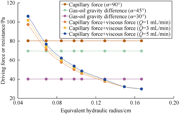
The equivalent hydraulic radius was calculated based on the fracture apertures shown in Table 1. Then, if the length of retained oil column is assumed as 1.0 cm, and the flow rate in capillary is 0.2 mL/min, the gas-oil gravity differences and flow resistances (capillary force+viscous force) in the fractures with different apertures and dip angles can be obtained according to Equations (1)-(3) (Fig. 7). It can be seen that as the equivalent hydraulic radius decreases, the flow resistance of oil gradually increases. When the equivalent hydraulic radius or fracture aperture reduces to a certain value, flow resistance is greater than gas-oil gravity difference and larger driven pressure difference is required to displace oil.
Fig. 7.
Fig. 7.
Gas-oil gravity difference and crude oil flow resistance in fractures with different apertures and dip angles.
3. Results and discussion of NAGD
3.1. The impact of injection-production relationship on NAGD
3.1.1. Homogeneous fractured-vuggy reservoir
Fig. 8 shows the distribution of oil at different stages of gas flooding in experiment ①-a. It is clear that the gravity difference between gas and oil was obvious during gas flooding. Gas channeled into Well No. 2 in high part shortly after the beginning of gas injection (Fig. 8b), so oil and gas produced simultaneously. The oil-gas interface didn’t change after complete gas channeling. After shutting in Well No. 2, gas-oil interface pushed down steadily (Fig. 8c) until gas channeled in the whole interval of Well No. 4 in low part. Gas mainly channeled through the fractures connecting with Well No. 4 (Fig. 8d). The displacement efficiency of the part above the fracture was greater than 95% (area above the gas-oil interface in Fig. 8d), while it was less than 5% in the area below the fracture.
Fig. 8.
Fig. 8.
Distribution of crude oil at different stages of gas flooding in experiment ①-a.
Fig. 9 shows the distribution of oil at different stages of gas flooding in Experiment ①-b, it can be seen that the gas-oil interface pushed down steadily when gas was injected in Wells No. 1 and No. 2 simultaneously (Fig. 9b). And it is similar to the characteristics of the case of gas injection at the top and production from whole-interval with Well No. 2 closed. The difference is that no gas channeled before a great deal of oil was displaced out; Comparing with Well No. 3, Well No. 4 connects with the reservoir at a higher position with straight fractures, so it had gas channeling earlier. When Well No. 4 was shut in, some oil in the vugs was driven out through Well No. 3 before gas channeling (area circled by blue dashed line in Fig. 9d).
Fig. 9.
Fig. 9.
Distribution of crude oil at different stages of gas flooding in experiment ①-b.
Fig. 10 shows the distribution of remaining oil after gas flooding in experiments ①-a and ①-b. The remaining oil can be divided into three types: (1) Remaining oil retains in the blind ends of vugs and fractures connecting with low-angle fractures and the blind ends of lower vugs caused by poor connectivity and gravity difference (blue dashed line section, named type A). (2) Remaining oil retains in the bottom of vugs caused by gravity difference (red dashed line section, named type B). (3) Remaining oil located at the bottom of reservoir due to the configuration between the producer and reservoir (pink dashed line section, named type C). The first two kinds of remaining oil were the same under the two injection-production patterns, while the third kind was more in the top gas injection and whole-interval production experiment.
Fig. 10.
Fig. 10.
Distribution of remaining oil in experiments ①-a and ①-b.
Fig. 11 shows the variation curves of recovery in experiments ①-a and ①-b. It can be seen that as the production goes on, all producers completely channel. The rising speed of recovery decreases sharply, and an obvious inflection appears (inflection of complete channeling). The oil production rate of whole-interval production and bottom production are nearly the same at the beginning period. As the increase of injected volume, gas first channels in Well No. 2 for whole-interval production. Then, oil production rate decreases, and recovery increases slowly. The development effect is worse than the bottom production mode. Therefore, when NAGD is applied, the perforating interval of producer should be at low structural position of the reservoir, which can delay gas channeling and reduce remaining oil zone. In addition, the wells at high structural position should be shut in timely after gas channeling to improve the utilization of injected gas.
Fig. 11.
Fig. 11.
Recovery degree of experiments ①-a and ①-b.
3.1.2. Heterogeneous fractured-vuggy reservoir
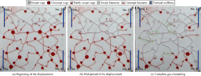
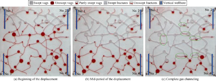
Figs. 12 and 13 show the distribution of oil at different stages of gas flooding in experiments ①-c and ①-d. It can be seen that although there is heterogeneity in fractures, the aperture of fracture is large, so the flow resistance in fractures is very small, and gas-oil interface can push forward steadily. The whole displacement process is similar to homogeneous fracture model.
Fig. 12.
Fig. 12.
Distribution of crude oil at different stages of gas flooding in experiment ①-c.
Fig. 13.
Fig. 13.
Distribution of crude oil at different stages of gas flooding in experiment ①-d.
Fig. 14 shows the distribution of remaining oil after gas flooding in Experiments ①-c and ①-d. It can be seen that when fracture aperture is large, heterogeneity has little impact on the type and distribution of remaining oil in NAGD, and only small amount of remaining oil is left in fractures with small aperture (green dashed line section, type D).
Fig. 14.
Fig. 14.
Distribution of remaining oil in experiments ①-c and ①-d.
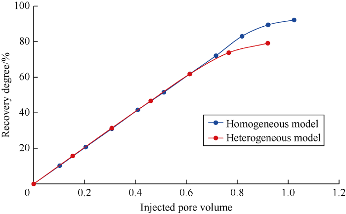
Fig. 15 shows the variation curve of recovery in Experiments ①-c and ①-d. It can be seen that it is similar to the experiment of the homogeneous fractured-vuggy reservoir (Fig. 11). The difference is that gas channeling occurs earlier in Well No. 2 for whole-interval production, so the rising speed of recovery is slower than the bottom production in the early stage. Comparison shows the recovery of the homogeneous model and that of the heterogeneous one (Figs. 11 and 15) are very close. The ultimate recoveries are 86.0% and 70.7% for bottom and whole-interval production of the homogeneous model, respectively, and those of the heterogeneous model are 83.2% and 70.0%, respectively. Apparently, although there is heterogeneity in fractures, it has small impact on NAGD in fractured-vuggy reservoir if the fracture aperture is large.
Fig. 15.
Fig. 15.
Recovery degree of experiments ①-c and ①-d.
Figs. 16 and 17 show the distribution of oil at different stages of gas flooding in Experiments ①-e and ①-f. It can be seen that as fracture aperture reduces, the gas-oil interface is more uneven than the homogeneous model or heterogeneous model with large-aperture fracture (Fig. 16c). The main reason is that the flow resistance of oil in wide fractures is small, so the advance speed of gas-oil interface is fast. In contrast, the resistance in narrow fractures is large, so the displacement is slow under gas driving pressure difference and gravity.
Fig. 16.
Fig. 16.
Distribution of crude oil at different stages of gas flooding in experiment ①-e.
Fig. 17.
Fig. 17.
Distribution of crude oil at different stages of gas flooding in experiment ①-f.
Fig. 18 shows the distribution of remaining oil after gas flooding in experiments ①-e and ①-f. We can see that a great deal of Type D remaining oil is left in the swept area besides the three types of remaining oil in experiments ①-a and ①-b. That is because small driving pressure difference is required for oil flow in large fractures, which can easily form dominant flow channels. In contrast, in fractures with small aperture, the flow resistance of oil (capillary force+viscous force) is larger or equal or slightly smaller than the driving forces (driving pressure difference+gas and oil gravity difference), which makes it difficult to replace oil and easy to form remaining oil.
Fig. 18.
Fig. 18.
Distribution of remaining oil in experiments ①-e and ①-f.
Fig. 19 shows the recovery in experiments ①-e and ①-f. Comparing Figs. 11, 15 and 19, we can see that the ultimate recovery of Model III is obviously lower than Models I and II. The recovery of bottom and whole-interval production modes are 69.3% and 54.7%, respectively. Model I has the longest gas-free production period (ends at 0.8 PV gas is injected), Model II is the second (ends after 0.7-0.8 PV gas is injected), Model III is the shortest, (ends after 0.6-0.7 PV gas is injected). This indicates that when there is fracture heterogeneity, the flow capacity of oil in different fractures differ widely, which has a significant impact on the development effect.
Fig. 19.
Fig. 19.
Recovery degree in experiments ①-e and ①-f.
Based on the results of experiment ①, formation mechanisms of remaining oil can be divided into four types as shown in Table 3.
Table 3 Types of remaining oil and formation mechanisms.
| Types of remaining oil | Existence form | Formation mechanism |
|---|---|---|
| Type A | The blind end of vug and fracture connected to low- angle fractures, and the blind end of lower vugs | Poor connectivity between fractures and vugs and poor gravity difference |
| Type B | The bottom of fracture-vug connected point | Poor gravity difference |
| Type C | Below the location of the production well connected with reservoir | Relationship between the production well position and reservoir |
| Type D | Small-aperture and low-angle fractures | Flow resistance is higher or close to gas-oil gravity difference |
3.2. Impact of injection rate on NAGD
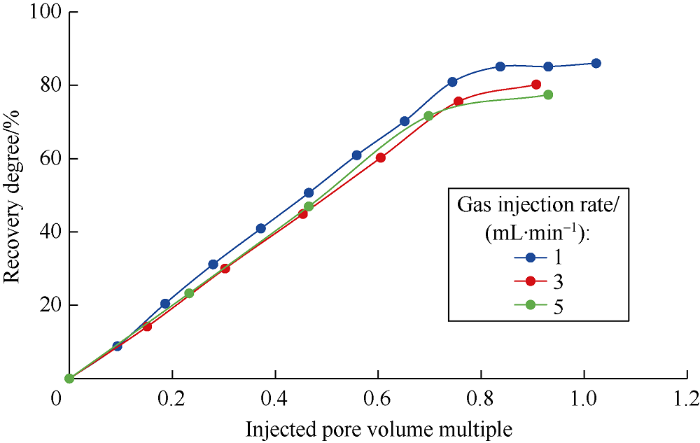
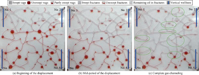
Figs. 20 and 21 show the distribution of oil at different stages in Experiments ②-a and ②-b, respectively. Comparing with Fig. 9, as the increase of injection rate, the regularity of gas-oil interface becomes worse, and the displacement of remaining oil in the upper fractures and vugs by gravity difference is slower, so the remaining oil in fractures and some vugs increases (green dashed line zones in Fig. 20c and 21c).
Fig. 20.
Fig. 20.
Distribution of crude oil at different stages of gas flooding in experiment ②-a.
Fig. 21.
Fig. 21.
Distribution of crude oil at different stages of gas flooding in experiment ②-b.
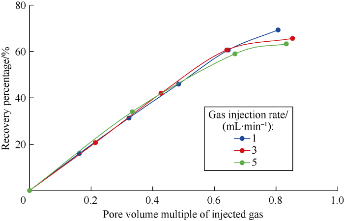
Fig. 22 shows the recovery curves of Experiments ①-b, ②-a, and ②-b. It can be seen that as the increase of injection rate, gas channeling time of all producers becomes shorter, and the ultimate recovery decreases.
Fig. 22.
Fig. 22.
Recovery degree in experiments ①-b, ②-a, and ②-b.
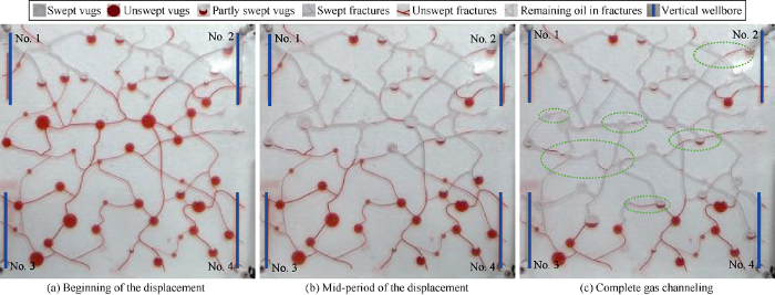
Figs. 23 and 24 show the distribution of crude oil at different stages of gas flooding in Experiments 2-c and 2-d, respec-
tively. Comparing with Fig. 17, as gas injection rate increases, gas-oil interface becomes more irregular, and the remaining oil in fractures and vugs increases. Comparing with the homogeneous model, the flow resistance in small-aperture and low-angle fractures is larger, so more oil is left behind (in the area outlined by green dashed line in Figs. 23c and 24c). Relationships of dip angle, displacement velocity, gravity difference, crude oil flow resistance and fracture aperture were calculated by equations (1)-(3) (Fig. 25). We can see as the displacement rate increases, flow resistance gradually increases, and some oil in small-aperture and low-angle fractures which can be displaced out at the original low displacement rate may be retained.
Fig. 23.
Fig. 23.
Distribution of crude oil at different stages of gas flooding in experiment ②-c.
Fig. 24.
Fig. 24.
Distribution of crude oil at different stages of gas flooding in experiment ②-d.
Fig. 25.
Fig. 25.
Relationship of dip angle, displacement velocity, gravity difference, crude oil flow resistance and fracture aperture.
Fig. 26 shows the recovery curves of experiments ①-f, ②-c, and ②-d. It can be seen that as the injection rate increases, the ultimate recovery decreases. Comparing with Figs. 22 and 26, gas channeling inflections of all the heterogeneous models appear around 0.6-0.7 pore volume, while that of homogeneous ones appear around 0.7-0.8 pore volume. Moreover, all the heterogeneous models have lower ultimate recovery than the homogeneous ones.
Fig. 26.
Fig. 26.
Recovery of experiment ①-f, ②-c, and ②-d
3.3. The impact of horizontal well on NAGD
It can be seen from Experiments ① and ② that the remaining oil rich zone is closely related to the configuration between the producer and reservoir. Therefore, the displacement experiment with horizontal well was designed. Figs. 27 and 28 show the distribution of oil at different stages of gas flooding in experiments ③-a and ③-b, respectively. Gas-oil interface in the homogeneous model pushes down steadily, but it is less steady in the heterogeneous one. The distribution of remaining oil shows that the remaining oil rich zone almost disappears in the horizontal well scenario. However, the remaining oil in blind ends of fractures and vugs and bottom of vugs controlled by connectivity, gravity difference, and configuration between fractures and vugs still exists. Moreover, the oil in the fractures and vugs which are at the bottom of the "V" configuration (area circled by red dashed line) cannot be produced. There is more remaining oil in small-aperture and low-angle fractures in the heterogeneous model as well.
Fig. 27.
Fig. 27.
Distribution of crude oil at different stages of gas flooding in experiment ③-a.
Fig. 28.
Fig. 28.
Distribution of crude oil at different stages of gas flooding in experiment ③-b.
Fig. 29 shows the recovery curves of experiments ③-a and ③-b. It can be seen that the heterogeneous model has earlier gas channeling inflections, and ultimate recovery about 10% lower than the homogeneous one.
Fig. 29.
Fig. 29.
Recovery degree of experiments ③-a and ③-b.
3.4. The impact of plane displacement on NAGD
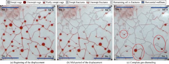
Fig. 30 shows the distribution of remaining oil in gas flooding of experiment ④. The content of remaining oil in the homogeneous model is much less than that in the heterogeneous one (blue dashed line section). The distribution of remaining oil in Fig. 30b and 30c is very similar. During the plane displacement process in the heterogeneous model, the flow resistance of oil is larger in fractures with small aperture, so the oil in small-aperture fractures and their connected vugs is retained.
Fig. 30.
Fig. 30.
Distribution of remaining oil in experiment ④.
There is a lot of remaining oil in the blind ends of fractures and vugs in both homogeneous and heterogeneous models due to the poor connectivity (red dashed line section). And the remaining oil has nothing to do with the configuration between fractures and vugs. The oil in the blind ends of upper fractures and vugs can be driven out by gas-oil gravity difference in vertical displacement, but it can’t be driven out in plane displacement. In addition, there is remaining oil caused by the injector and producer locations (pink dashed line section). The remaining oil in plane displacement can be divided into the following three types according to its forming mechanisms (Table 4).
Table 4 Types and formation mechanisms of remaining oil in experiment ④.
| Remaining oil type | Existence form | Formation mechanism |
|---|---|---|
| Type A | Blind ends of upper fractures and vugs | Poor connectivity of fractures and vugs |
| Type C | The lower parts of the reservoir | Regions not effectively controlled by the injector and producer |
| Type D | Small-aperture fractures and their connected vugs | Fracture heterogeneity |
4. Conclusions
From the experiments of NAGD in fractured-vuggy reservoirs, it is found that top gas injection and bottom production has better effect than top gas injection and whole-interval production. Gas channeling is more likely to occur in the producer at high structural position, and it should be shut in timely to improve the utilization of injected gas. The remaining oil can be divided into four types: that in the blind vugs horizontally connected with fractures, the bottom of connected points between fractures and vugs, the small-aperture and low-angle fractures, and the position below the connection of the well and reservoir.
During NAGD in fractured-vuggy reservoirs, because the resistance differences of oil flow in fractures, gas-oil interface advances steadily in both homogeneous and heterogeneous reservoirs with high-aperture fractures. But in some fractures with low-aperture in heterogeneous reservoirs, the displacement of oil is hysteretic. As a result, remaining oil is formed.
As the gas injection rate increases, the resistance difference increases, and gas channeling becomes earlier, so the recovery is lower. Horizontal well injection-production has the best development effect in the reservoir without bottom water, with hardly any remaining oil left.
In fractured-vuggy reservoirs, the impact of fracture heterogeneity is more obvious in gas plane displacement. The types of remaining oil can be divided into: remaining oil in all blind ends of fractures and vugs caused by poor connectivity, that in small-aperture fractures and their connected vugs caused by heterogeneity, and that not effectively controlled by injectors and producers
Nomenclature
g—gravity acceleration, m/s2;
l—the length of the oil column, m;
pc—capillary force, Pa;
pf—viscous force, Pa;
pG—gas-oil gravity difference, Pa;
Q—flow rate in capillary, m3/s;
rc—equivalent hydraulic radius, m;
α—fracture dip, (°);
Δρgo—gas-oil density difference, kg/m3;
θgo—wetting angle, (°);
σgo—interfacial tension between oil and gas, N/m;
μo—oil viscosity, Pa·s.
Reference
Features and hierarchical modeling of carbonate fracture-cavity reservoirs
Identification of the porous-cave-fractured reservoir in metamorphic rocks by logging analysis.
Combination of volcanic reservoir spaces and hydrocarbon storage modes: A case study on the carboniferous system in Chepaizi area, west of Junggar basin
Reservoir characteristics and influencing factors of the Permain Xiazijie formation sand and gravel reservoir in Red 153 area of the Hongshanzui Oilfield, Junggar Basin
Fracture identification and prediction of sandy conglomerate reservoirs with ultra-low permeability: A case study of well Hong 153 on the northwest margin of Junggar Basin
Features of the carboniferous volcanic rocks fracture reservoirs in Hongshanzui Oilfield, Junggar Basin
DOI:10.1007/s12583-013-0397-z URL [Cited within: 1]
Characteristics of deep-buried frag mental reservoirs in central Junggar Basin and the effect of hydrocarbon emplacement on reservoirs’ diagenetic mineral evolution
Applications of natural zeolites in water and wastewater treatment
DOI:10.2138/rmg.2001.45.15 URL [Cited within: 1]
Study on seepage rules of Chang 10 reservoir in Ansai oilfield
Investigation of flue gas displacement and storage after the water flooding in full diameter conglomerate long core


