


Introduction
Oil and gas resources are rich in the Kuqa foreland thrust belt, Tarim basin, especially the Keshen-Dabei zone, with an area of 629.4 km2 and natural gas resource of 10797.62×108 m3[1], has a good exploration prospect. Salt rocks are rich and intense in deformation in this area: the post-salt layer has folds related to slippage developed, while the pre-salt layer has mainly thrust deformation, and fault-related folds and fault blocks in the basement[2,3,4,5]. Results of previous studies mainly include: (1) Based on the membrane theory, with the aid of elastic-plastic model, it is concluded in the early stage of salt deformation in the western Kuqa foreland thrust belt, the main factor affecting salt deformation was differential loading of thick sediment deposition in Baicheng sag, while that in the late stage was the extrusion stress[6]. (2) Based on seismic interpretation and balanced profile study, the evolu-tion models of Tuzimaza salt wall and Quele salt nappe were proposed[7]. (3) Based on physical simulation experiments, it is concluded that salt deformation in Kuqa foreland thrust belt was mainly affected by regional compression and syn-tectonic sedimentation[8]. (4) By combining 2D physical modeling experiment and numerical simulation, the effects of three factors salt boundary, regional change of tectonic stress and differential loading (sedimentary loading and local tectonic loading) on salt deformation in Kuqa depression were figured out[9]. (5) Based on the 2D discrete element simulation, it is considered that salt deformation in Kuqa foreland thrust belt is controlled by rate and action time of strain, the distribution of salt rocks, preexisting salt diapirs, preexisting faults and paleo-uplift in the basement[10]. However, these studies are all based on the researches of 2D data, which can only simulate a single section but cannot reflect the lateral flow and structural styles of salt rock in the direction perpendicular to the principal stress in the 3D space, leading to poor understanding on the formation mechanism of salt structures.
Compared with Hertz-Mindlin model of 2D discrete element method, the linear model of the 3D discrete element method can set the normal stiffness and tangential stiffness of the particle and wall. Underground salt rock is similar to Newton fluid, when the particle and particle or particle and wall contact, the acting force between them can be calculated from force - displacement relationship, which has advantage in analysis of large displacement problems[11]. Meanwhile, parallel bonding between particles can be simulated, which is similar to the cementing material of a certain volume acting within a certain range from the contact point, and can not only transmit force but also transmit moment. This way can better reflect the properties of different rocks and is more suitable for the studies of rupture and flow of particle aggregates[12]. In this work, taking the Keshen and Dabei work areas as examples, we used the 3D discrete element method to analyze the salt deformation in the principal stress direction and direction perpendicular to the compression to find out the controlling factors and deformation mechanism of salt structures in the western Kuqa foreland thrust belt.
1. Geologic setting
Kuqa foreland thrust belt is in northern Tarim Basin, held between southern Tianshan orogenic belt and the Tabei uplift. From the Paleogene to the Miocene, Kuqa area was in the environment of salt lake and drought lake to salt lake, when salt rocks of Paleogene Kumugeliemu Group (E1—2km) and Neogene Jidike Group (N1j) deposited, which constitute the region's main decollement layers. With the Kuqa sag as dividing line, in the western foreland thrust belt occurs mainly Kumugeliemu Group salt rock, which is wider in distribution range and thickness (up to over 6 000 m); while in the east comes mainly the Jidike Group salt rock, with smaller distribution area and thickness (up to about 1 800 m thick)[4-5, 13-16] (Fig. 1). The strong compression and existence of salt detachment layer make the structural deformation of Kuqa foreland thrust belt feature “east-west segmentation, north-south zonation and upper-lower stratification" on the whole: from the west to the east, it is divided into three sections of Wushi sag, Baicheng sag and Yangxia sag; from north to south, it is divided into five tectonic deformation belts, northern monoclinal belt, Kelasu-Yiqikelike structural belt, Wushi-Baicheng- Yangxia sag belt, Qiulitage structural belt and southern slope belt. Among them, the strong contraction-type deformation belts (Kelasu-Yiqikelike structural belt and Qiulitage structural belt) separate the weak deformation belts (northern monoclinic belt, central depression belt and southern slope belt)[3, 17-19]. The 3D Keshen-Dabei work areas are in the western Kuqa foreland thrust belt, where the salt rock of the Kumugeliemu Group causes stratified deformation[6].
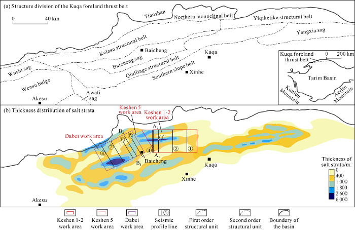
Fig. 1.
Structure division and salt thickness distribution of the Kuqa foreland thrust belt.
2. Seismic interpretation of 3D Keshen-Dabei work areas
It can be seen from 3D seismic interpretation that the salt rocks in Keshen and Dabei work areas are quite different in spatial distribution (Fig. 2). In the Keshen 1-2 work area, the salt rock is mainly concentrated in the triangle zone formed by presalt thrust faults in the north, while in the south where salt withdrawal synclines developed, the salt rock layers are thinnest at the syncline core, and salt welding structures even appear in some parts. In the Dabei work area, the salt rock mainly accumulates in the salt anticline (Dawanqi anticline) in the south, and can be more than 6 000 m thick at the core of the anticline. In the northern part of Dabei work area, affected by Tuzymazar fault, salt diapir develops. In some parts, the salt rock breaks through earth surface with thrust faults, forming salt wall (Tuzymazar wall). In the Keshen 5 work area between Keshen 1-2 work area and Dabei work area, the spatial distribution of underground salt rock has the character of transition, with salt thickness centers both in the north and south.
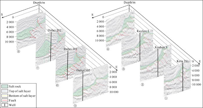
Fig. 2.
Joint seismic profiles of the Keshen-Dabei 3D work area.
In Keshen work area, salt deformation mainly occurs at the contraction end in the north, and the post-salt layer, the salt layer and pre-salt layer are quite different in deformation pattern. This is illustrated by the major section through Well Keshen-4 (Fig. 3). The post-salt layer has deformations mainly in the form of wide and gentle large-scale syncline, growing characteristics, and decollement folds and thrusts near the contraction end. The salt layer varies greatly in thickness from north to south, and the salt rock mostly accumulates in the fault triangle zone near the north, while the salt layer is thinner in the south. In the pre-salt layer, there are imbricated thrust faults, and dual-thrust structures in the part far from the contraction end; and the closer to the contraction end, the larger the uplift amplitude of the pre-salt layer, and the larger the fault throw is. In addition, from east to west, the deformation patterns of the sections in the direction parallel to the principal stress are similar.

Fig. 3.
Interpreted major seismic profile through Well Keshen 4 in the Keshen area of the western Kuqa foreland thrust belt (The section position is shown in
In Dabei work area, we can see from the major section through Well Dabei-3 (Fig. 4) the salt rock mainly accumulates in the salt anticline in the south; while in the north, the salt rock arches into salt wall (Tuzymaza wall), and the salt layer thins in the position where the salt anticline joins the salt wall. The presalt layer has deformation pattern similar to that in the Keshen work area, with imbricate thrust faults developed. The formation above salt has anticlinal structure in the position far from the contraction end, and a small-scale syncline with one wing cut off by the salt wall occurs in the position where the salt anticline and the salt wall contact. From east to west, the deformation patterns on section of Dabei work area parallel to the principal stress direction differ somewhat, specifically, the Dawanqi anticline in the south has larger uplift amplitude and thicker salt layer, and towards both sides of the Dawanqi anticline, both the uplift amplitude and the thickness of the salt layer decrease gradually.
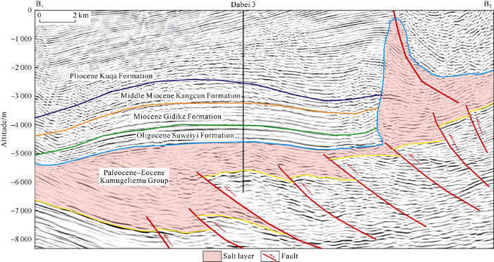
Fig. 4.
Interpretation of seismic profile through Well Dabei 3 in the Dabei area of the western Kuqa thrust belt (the section position is shown in
3. Discrete element method and initial model design
3.1. Discrete element method and experimental parameters
Discrete element method (DEM) is a numerical simulation method based on the contact criterion between discrete particles. By using time-displacement finite difference method, the movement of particles is calculated under Newton's law, which can effectively simulate the elastoplastic deformation process[20]. Based on the stress and displacement criteria, discrete element method can be used to calculate the displacement of particles, with sliding and rupture between particles permitted[21,22,23]. This method is suitable for analyzing structural deformation pattern under big strain, and has been widely used to simulate the deformation process of shallow crust structure, fault system and shear belt[21,22,23]. This study used the DEM linear model. The particle and wall elements in the model have two basic parameters, normal stiffness and tangential stiffness. When a particle contacts with another particle or the wall, the force between them can be calculated through the force-displacement relationship.
In the numerical simulation, different boundary conditions of the model were firstly set up, and the basic geometric model was established after multiple debugging. The ratio of the model size and the actual geologic body size was set at 1:100. Within the space of 250 m (x), 250 m (y) and 150 m (z), particles with the radius of 1.5-2.0 m were randomly generated. After setting the gravity, particles were naturally compacted and balanced, and the top particles were gradually removed, only the particles within the space of 250 m×250 m×60 m were remained. The particles with a z-axis coordinate range of 0-20 m were set as the presalt layer, the particles with a z-axis range of 20-35 m were set as the salt layer, and the particles with a z-axis range of 35-60 m were set as the post-salt layer. The intermediate layer of each layer was marked, to make the deformation structures in the later stage easy to identify.
Reasonable parameters are the basis of numerical simulation. When the experiments are carried out by the 3D Particle Flow Code (PFC3D), the microscopic parameters of particles are often determined by triaxial mechanical simulation experiment. The triaxial mechanical simulation experiment model was composed of a cylindrical wall around generated particles and the upper and lower compression plates. In the process of compression, the upper wall compressed and sheared the sample, while the lower wall remained motionless. The cylindrical wall maintained constant confining pressure through servo system in the process of compression and shearing. The collection and sorting of stress and strain data were determined by tracking the stress and relative displacement of the wall. Through a large number of triaxial mechanical simulation experiments and constant adjustment of the particle parameters, when the results of the simulation and laboratory experiment are in high agreement, the parameter values in the mathematical model are equal to the values of the actual material. But in the actual simulation, because there is no experimental data of triaxial mechanics of the study area available, rock mechanical parameters based on the rock tests by the Geomechanics Lab, Tarim Geophysical Center and the previous studies are as follows: the post-salt and pre-salt layers are 2400 kg/m3 and 2600 kg/m3 in density respectively; the same in Young's modulus (60 MPa), Poisson's ratio (0.25) and cohesion (10 MPa); 35° and 40° in internal friction angle respectively. The salt layer has a viscosity of 1×10¹⁹ Pa, a volume modulus of 1×10⁴ MPa and a shear modulus of 1×10³ MPa[9, 24-26]. In this study, we carried out triaxial mechanical simulation experiments and referred to previous studies in the selection of parameters[27,28,29]. The specific particle parameters are shown in Table 1.
Table 1 The microscopic physical parameters of the discrete element simulation.
| Layer | Density/ (kg•m-3) | Particle normal stiffness/ (N•m-1) | Particle tangential stiffness/ (N•m-1) | Friction coefficient | Damping coefficient | Contact type | Normal critical damping ratio | Normal stiff- ness of parallel bond/(N•m-1) | Tangential stiffness of parallel bond/(N•m-1) | Parallel bond tensile strength/N | Parallel bonding cohesion/N |
|---|---|---|---|---|---|---|---|---|---|---|---|
| Post-salt particle | 2, 400 | 1010 | 1010 | 0.30 | 0.7 | Linear parallel bond model | 0.7 | 108 | 5 × 10⁷ | 2 × 10⁵ | 5 × 10⁴ |
| Salt layer particle | 2, 200 | 1010 | 1010 | 0.05 | 0.7 | Linear model | 0.7 | ||||
| Pre-salt particle | 2, 600 | 1010 | 1010 | 0.30 | 0.7 | Linear parallel bond model | 0.7 | 108 | 5 × 10⁷ | 2 × 10⁵ | 5 × 10⁴ |
| Boundary particle | With inheritance | With inheritance | Linear parallel bond model | 0.7 | 106 | 5 × 10⁶ | 2 × 10³ | 5 × 10² |
In this study, it was considered that the underground salt rock was similar to Newtonian fluid, and the model adopted was linear model, while the commonly used parallel bond model was adopted for both the post-salt and pre-salt layer. The particles contact through parallel bond, which can transfer both force and moment[30,31,32]. At the contact boundaries between the salt layer particle and the post-salt and pre-salt particles, the model adopted between the particles is also parallel bonding model. The specific parameters are listed in Table 1. In addition, in the simulation process, both the normal stiffness and tangential stiffness of the wall were set at 1×10¹⁰ N/m, the friction coefficient between the wall and the particles was set at 0.5, and the rigid wall on the right side of the model squeezed in the negative direction of the X-axis at a rate of 1 m/s.
3.2. Model design
On the basis of the above work, the initial model of the work area was established by referring to previous physical and numerical experiments as well as the evolution model from balanced section study[7, 33] and the influencing factors of salt deformation, including distribution of salt rock[6], basement structures[15], pre-existing faults, pre-existing diapirs[10] and differential nappe action of South Tianshan Mountain[34,35].
3.2.1. Model of Keshen work area
In the model, two pre-existing faults were set at the contraction end: one was through the point (170, 0, 20) and parallel to the Y-axis, with the included angle with Plane xOy of 45°; and the other through the point (205, 0, 25) and parallel to the Y-axis, with the included angle with Plane xOy of 60°. The basement near the contraction end was uplifted step-like due to the pre-existing faults, and the uplifted presalt layer was 25 m and 30 m thick respectively, while it was 20 m thick far from the contraction end. The change of basement morphology also affected the thickness of the salt layer, which was the smallest of 5 m near the contraction end and 15 m far from the contraction end. The top surface of the salt layer was parallel to the horizontal plane (Fig. 5).

Fig. 5.
Three-dimensional discrete element model of the Keshen area in the western Kuqa foreland thrust belt.
In addition, the syn-deposition of particles was considered in the model. Two batches of syn-sedimentary particles were added in this model. The first stage of 5000 particles, 1.5-2.0 m in size were randomly generated in the range of 0-125 m (x), 0-250 m (y) and 100-125 m (z) (Fig. 5). The particles were consistent in property with the post-salt layer particles, and the particles gradually fell to stability under gravity to simulate the effect of syn-deposition on the model during compression. When the model ran 100 000 steps, the second batch of syn-sedimentary particles with the same properties as the first batch were generated in the same range.
3.2.2. Model of Dabei work area
The Dawanqi anticline used to be the center of the paleo-salt lake in the south of the Dabei work area[36]. Therefore, in this model, the salt layer was thicker far from the contraction end, and thinned stepwise toward the periphery to simulate the paleo-salt lake deposition. In the range of 30-110 m (x) and 85-165 m (y), the salt layer was thickest (27 m); in the range of 20-120 m (x) and 75-175 m (y), the salt layer was 23 m thick; in the range of 10-130 m (x) and 65-185 m (y), the salt layer was 19 m thick; in the rest part, the salt layer was 15 m thick (Fig. 6). In addition, the Tuzimaza salt wall in the north of the Dabei work area came from the pre-existing salt diapir, so a pre-existing salt diapir was set near the contraction end of this model[7]. The linear salt diapir was located above the salt layer, and its extension direction was parallel to the Y-axis direction. The right end of the diapir (20 m wide and 20 m high) was 65 m away from the extruding salt wall. The top of the diapir had a certain radian on the Plane xOz.
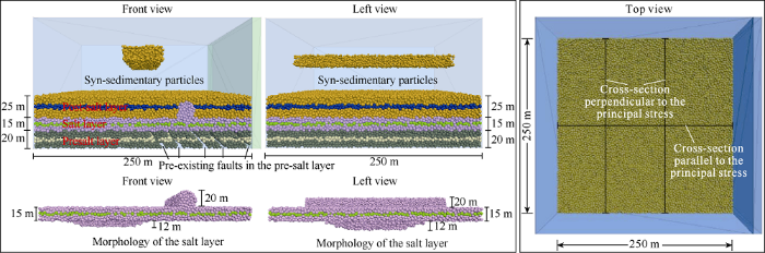
Fig. 6.
Three-dimensional discrete element model of the Dabei area in the western Kuqa foreland thrust belt.
Then, five pre-existing faults were set near the contraction end, through points (125, 0, 20), (150, 0, 20), (175, 0, 20), (200, 0, 20) and (225, 0, 20) respectively and parallel to the Y-axis, at the included angle with the Plane xOy of 45°. Different from the Keshen model, this model had no basement uplift near the contraction end, and had pre-existing faults not penetrating into the salt layer. In addition, this model also had 2 batches of syn-sedimentary particles. The first batch of 2000 particles 1.5-2.0 m in size were randomly generated in the range of 100-150 m (x), 0-250 m (y) and 100-120 m (z) (Fig. 6). Similarly, when the model ran 100 000 steps, the second batch of syn-sedimentary particles with the same properties as the first batch were generated in the same range.
4. The results
4.1. Keshen work area
From the profile in the principal stress direction (through point (0, 125, 0) with the normal vector (0, 1, 0)), it can be seen the deformation is mainly at the contraction end and forward spread, and the pre-existing fault near the contraction end was activated first, and the early uplift of the basement raised further. As the compression continued, the shortening of the model further increased, the pre-existing faults gradually increased in dip angle and fault throw gradually, and penetrated into the salt layer. In addition, away from the contraction end, new thrust faults developed in the presalt layer gradually, forming imbricate thrust structures (Fig. 7). In the post-salt layer, a large-scale anticline formed near the contraction end under the action of compression, while the syn-deposition led to the increase of thickness of the post-salt layer away from the contraction end and the formation of a large- scale syncline. With the compression going on, the joint of the syncline and anticline gradually became steep. When the model ran 200 000 steps, the wing reversed, forming reverse anticline and reverse syncline (Fig. 7).

Fig. 7.
Cross-sectional view of typical salt structure evolution in the Keshen area (in principal stress direction).
Considering the denudation in the later stage, the section in the middle of the model parallel to the principal stress was cut off at the top (Fig. 8b). Comparison shows the section of the model after running 140 000 steps with the top denuded has high similarity in morphology with the seismic section through Well Keshen4 in Keshen work area (Fig. 3).
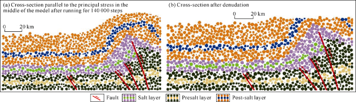
Fig. 8.
Cross-sectional view of typical salt structure evolution in the Keshen area (middle of the model).
Comparing the section away from the contraction end (through point (100, 0, 100) with the normal vector (1, 0, 1)) with that near the contraction end (through point (150, 0, 0) with the normal vector (1, 0, 0)) perpendicular to the principal stress, it can be seen that in the section away from the contraction end, the deformation of each layer is weak, and the marked salt layer has hardly deformed; while in the section near the contraction end, because the section crosses the thickness center of the salt layer, the salt layer is thick and has irregular pattern on the top surface (Fig. 9). In addition, on the section near the contraction end, complex fold patterns can be seen in the salt marker layer, with marker broken in some parts, which indicates that the salt rock had strong lateral flow near the contraction end.
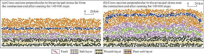
Fig. 9.
Cross-sectional view of typical salt structure evolution in the Keshen area.
Fig. 10 shows the particle motion vectors after running for 140 000 steps. Under the effect of continuous extrusion, particles near the contraction end had higher moving velocity while particles far from the contraction end had very low moving velocity. The area with the highest velocity was the position of the post-salt layer near the contraction end, and the moving velocity gradually decreases from the salt layer to the pre-salt layer, indicating the structural deformation mainly happens near the contraction end, and the deformation gradu-ally increases from the pre-salt layer to the post-salt layer, and the rocks in this area are easy to break and form thrust faults. In addition, the salt layer particles have a larger upward velocity component, which causes the strata in the contraction area to gradually arch up to form an anticline. And the particles in the direction perpendicular to the principal stress have a velocity component moving toward the center, and the closer to the center, the greater the velocity is, which indicates that the salt layer in the anticline is thick and has complex inner structures.

Fig. 10.
Vector diagram of particle motion of typical salt structure evolution in the Keshen area.
4.2. Dabei work area
It can be seen from the section of the Dabei work area in the principal stress direction from the simulation (Fig. 11) that the deformation is forward spread and more concentrated on the contraction end. The presalt layer has simpler deformation: the pre-existing faults reactivated and increased in fault throw, and the inclination of the faults gradually increased. On the section crossing the middle of the model parallel to the main stress direction after running for 150 000 and 200 000 steps, new basement faults can be seen. The salt layer is dominated by flow deformation. Continuous compression caused the pre-existing salt diapir near the contraction end to turn narrow but higher gradually, forming a salt wall, and the salt wall gradually tilted away from the contraction end. In the position far from the contraction end, the salt layer thickness center evolved into a salt anticline under the action of extrusion. The differential load caused by syn-deposition resulted in the thinning of the salt layer in the middle of the model and the salt rock accumulated more towards the salt anticline far from the contraction end. The post-salt layer has mainly fold deformation: under the action of compression, anticlines came up both near and far from the contraction end, while the post-salt layer subsided in the middle part of the model under the action of syn-deposition, forming synclinal structure. Meanwhile, dislocation can be seen on the salt marker layer on both sides of the salt diapir.
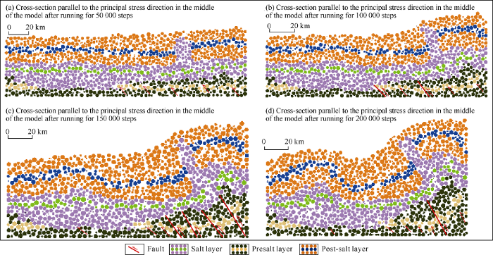
Fig. 11.
Cross-sectional view of typical salt structure evolution in the Dabei area (in principal stress direction, with stratigraphic division and extrusion direction same as those of
Comparison shows the section through the middle of the model parallel to the principal stress direction after denudation is quite similar to the seismic section through Well Dabei-3 in morphology (Fig. 12). Except that the specific number of presalt thrust faults and the shape of the salt wall are different from the actual seismic section, the deformation patterns of the post-salt layer, salt layer and presalt layer are very similar to those of the actual seismic section.
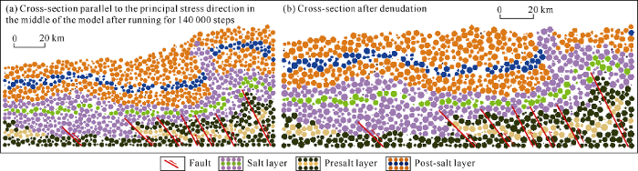
Fig. 12.
Cross-sectional view of typical salt structure evolution in the Dabei area (in the middle of the model).
Parallel to the principal stress direction, we selected the section far from the contraction end (through point (70, 0, 0) and normal vector (1, 0, 0)) which crosses the salt anticline, and the section near the contraction end (through point (155, 0, 0) and normal vector (1, 0, 0)) which crosses the salt wall. It can be seen from Fig. 13 that in the section far from the contraction end, the deformation of each layer is weak, and the salt marker layer only has small folds, indicating that the lateral flow of salt rock far from the contraction end is weak. In contrast, near the contraction end, as the section cut through the salt diapir, the salt rock is complex in distribution, and part of the salt body is separated from the source salt layer. Due to the obstruction effect of the boundary wall, on both sides of the section, the post-salt marker layer is broken off by the salt diapir. Compared with the section far from the contraction end, the inner salt marker layer is more complicated in deformation, with folds in larger amplitude and marker layer breaking in some parts, indicating that the salt rock near the contraction end is stronger in mobility.
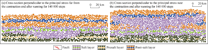
Fig. 13.
Cross-sectional view of typical salt structure evolution in the Dabei area.
Fig. 14 shows particle motion vectors of the model after running for 140 000 steps. It can be seen from the figure that with the extrusion going on, the particles near the contraction end move faster, while particles far from the contraction end move at lower speed, but the moving speed drops relatively smoothly and keeps at certain level far from the contraction end. This indicates that under the influence of the pre-existing linear salt diapir and the initial salt deposition center, the range of stratum deformation under compression is larger. The pre-existing salt diapir, salt deposition center and post-salt particles all have relatively large upward velocity components, causing the diapir near the contraction end to gradually arch up to form salt wall, and the salt layer and the post-salt layer far from the contraction end gradually uplift. In addition, in the direction perpendicular to the principal stress, the particles on both sides have velocity components moving toward the middle, and the particles in the middle tend to move upward and forward along the principal stress direction, which causes the salt rock to gradually gather toward the middle and arch in the middle, and inner salt structures to become more complex.

Fig. 14.
Vector diagram of particle motion of typical salt structure evolution in the Dabei area.
5. Discussion
The process of 3D discrete element numerical simulation is more complex and increases exponentially in computational amount than 2D discrete element numerical simulation[20,21,22,23]. Quantitative 3D simulation of specific research area is difficult. Keshen and dabei work areas in the western Kuqa foreland thrust belt have complex salt structure patterns and large range, so qualitative method was mainly used in simulation to find out the main factors controlling the salt structures in the area by setting different boundary conditions. Compared with 2D simulation, 3D simulation works better in finding out the effects of different factors on the salt structure and inner salt structure, and can comprehensively analyze the simulation results of the sections in directions same as and perpendicular to the principal stress. The salt structures are obviously segmented in both directions, and the simulation results are more consistent with the actual geological phenomena.
The collision between the Indian plate and the Eurasian plate led to the Cenozoic re-activation of the Tianshan structural unit and the formation of the foreland thrust belt in the piedmont of southern Tianshan[37]. The Keshen and Dabei work areas are in the same basin-mountain structure system, where the salt deformation in the direction of the principal stress is generally forward spread, mainly concentrated at the front of the mountain, and has vertical migration locally. In the Keshen work area, the compressive stress at the piedmont led to the reactivation of the pre-existing faults of the basement, which further raised the early basal uplift[15]; with the forward propagation of the compressive stress, new thrust faults developed successively under the salt layer, forming imbricated thrust structures. The morphology of salt layer is affected by both the piedmont compression and syn-deposition: the syn-sedimentation far from the piedmont would form a differential load on the salt layer, causing salt rock to have a tendency of withdrawal; while the compressive action in the piedmont made the salt layer to flow away from the piedmont. Under the dual effects of syn-sedimentation and extrusion, the salt layer far from the piedmont remains basically stable in thickness; while at the piedmont, the salt rock had a velocity component of moving upward along the faults, and accumulated in the salt triangle zone bounded by the sub-salt basement faults to form the thickness center of salt rock in this area. In the Dabei work area, the compressive stress from the piedmont also led to the reactivation of the pre-existing faults in the basement and development of new thrust faults and imbricated thrust structures. In addition, the Oligocene Suweiyi Formation and Quaternary conglomerate layers are sediments of piedmont fluvial and flood fan facies, and the progradation resulted in differential loading on the salt layer, thereby the formation of the pre-existing diapir[7]. The compressive stress led to the further development of the pre-existing linear salt diapir. When the salt rock moved along the principal stress direction, it had a larger vertical velocity component than the surrounding strata, thus giving rise to the Tuzimaza salt wall. According to reference [36], the Dawanqi anticline was the sedimentary center of the paleo-salt lake, with a thick salt layer accumulated in situ. The differential load caused by syn-deposition in the later stage led to the thinning of the salt layer in the middle of the work area. The salt rock gathered and uplifted in the Dawanqi anticline continuously, giving birth to the salt thickness center of the work area.
The sections in the direction perpendicular to the principal stress show near the contraction end, the salt rocks on both sides in the two work areas have a velocity component moving toward the middle, and the salt rock in the middle part shows a trend of moving upward and forward along the direction of the compression stress; and the closer to the middle part, the greater the rate of movement is, causing the salt rock to gradually gather towards and arch in the middle part. Salt structures are dominated by complex fold patterns, and there are structural combinations separating from the source salt layer. According to this trend, in some areas (especially in the middle of the work area), the salt rock could break through the surface with thrust faults. While in places far from the contraction end, the salt rock still had a velocity component moving toward the middle, but lower lateral flow capacity, and the deformation of each layer weakened. In the original not thick salt deposition area, the inner salt marker layer only had small-scale folds developed locally.
6. Conclusions
Based on the results of numerical simulation and seismic interpretation, the early uplifts, pre-existing faults, and syn- sedimentation near the contraction end are important factors affecting the deformation patterns of salt structures in the Keshen work area; whereas the initial sedimentary center of the salt layer, pre-existing salt diapir, pre-existing fault system, and syn-sedimentation are important factors affecting the deformation patterns of salt structures in the Dabei work area.
The 3D discrete element numerical simulation shows that the motion of the particles is mainly concentrated near the contraction end and gradually increases in intensity from the presalt layer to the post-salt layer. The deformation in the Keshen and Dabei work areas is forward spreading and concentrated in the piedmont. The compressive stress from the piedmont led to the reactivation of the pre-existing faults in the basement. Meanwhile, new thrust faults developed from the presalt layer successively, forming imbricate thrust structures. The salt layer and post-salt layer have more intense deformations near the piedmont, and thus complex fold patterns.
In the Keshen work area, the salt layer far from the piedmont has remained stable in thickness under the joint effect of syn-deposition and compression of the piedmont; while at the piedmont, due to the further uplift of the early uplifted basement, the salt layer had a larger upward velocity component, which caused the rock layer to gradually arch up to form an anticline. The salt rock accumulated in the salt triangle zone bounded by the presalt faults in the basement, forming the salt thickness center.
In the Dabei work area, under the compressive stress, the linear salt diapir near the piedmont had an upward velocity component, and further developed into the Tuzimaza salt wall. The salt layer in the middle of the work area thinned due to the differential load formed by the syn-sedimentation in the later stage. The salt rock moved toward the sedimentary center of the paleo-salt lake and gathered upward, gradually forming the Dawanqi anticline, which becomes the salt thickness center.
Compared with 2D simulation, 3D simulation can complete comprehensive analysis of salt deformation in directions parallel and perpendicular to the principal stress. During the process of salt deformation, the salt rock near the contraction end has stronger lateral mobility. The salt rock has a velocity component of moving toward the middle, and the closer it is to the middle, the greater the moving velocity is, causing salt rock to accumulate and deform strongly, giving rise to complex fold patterns, salt structural combination separating from source salt layer, and bursting of salt layer out of the earth surface with thrust faults in some areas.
Reference
Comparison in petroleum geology between Kuqa depression and Southwest depression in Tarim Basin and its exploration significance
Cenozoic salt structures and evolution in the western Kuqa depression, Tarim Basin, China
Differential salt tectonic deformation and segmentation of the Kuqa foreland fold-thrust belt, Tarim Basin, northwest China
Salt tectonics in the western Kuqa Depression and its relation to oil and gas distribution
The model of fracture development in the faulted folds: The role of folding and faulting
Major factors controlling salt structures in western Kuqa Depression, Tarim Basin
Compressional salt tectonics and synkinematic strata of the western Kuqa foreland basin, southern Tian Shan, China
Characteristics and mechanics of Cenozoic salt-Related structures in Kuqa foreland basins: Insights from physical modeling and discussion
Cenozoic salt tectonics and physical models in the Kuqa depression of Tarim Basin China
Deformation mechanisms of Kelasu tectonic belt in Kuqa foreland thrust belt: Insight from discrete element numerical simulation
Mode I-fracture simulation of concrete based on 3D distinct element method
Simulation of granular material behaviour using DEM
Kinematics characteristics of the Kuqa Depression in the Tarim Basin
The effect of salt thickness on fold lateral linkage: A case study of the anticlines in the leading edge of the western Kuqa fold and thrust belt, South Tianshan
Paleo-uplifts and salt structures and their influence on hydrocarbon accumulations in the Kuqa Depression
A sub-salt structural model of the Kelasu structure in the Kuqa foreland basin, northwest China
Structural segmentation and mechanism in Dabei-Keshen area of Kelasu structural belt, Kuqa Depression
Hydrocarbon migration and accumulation history in deep reservoirs: A case study of Mesozoic sandstone gas reservoirs in the Kelasu-Yiqikelike structural belt of the Kuqa Depression, Tarim Basin
Classification and combination characteristics of fractures in super-deep tight sandstone reservoir of Keshen Gasfield in Tarim Basin
Geometries of frontal fold and thrust belts: Insights from discrete element simulations
Influence of normal stress and grain shape on granular friction: Results of discrete element simulations
Discrete element simulations of gravitational volcanic deformation: 1. Deformation structures and geometries
A discrete element model for orogenesis and accretionary wedge growth
Criteria for selecting and adjusting ground-motion models for specific target regions: Application to central europe and rock sites
Evaluation of common mixing models for calculating bulk thermal conductivity of sedimentary rocks: Correction charts and new conversion equations
Comparison of evolutionary and static modeling of stresses around a salt diapir
Discrete-element modelling of extensional fault-propagation folding above rigid basement fault blocks
Structural evolution of calderas: Insights from two-dimensional discrete element simulations
Deformation and fault activity in space and time in high-resolution numerical models of doubly vergent thrust wedges
PFC and application case of caving study
Movement process simulation of high-speed long-diatance Jiweishan landslide with PFC3D
A constitutive model for anisotropic structured sandy soil based on micromechanical mechanism
Quantitative prediction of fracture distribution using geomechanical method within Kuqa Depression, Tarim Basin, NW China
Analysis of structure model and formation mechanism of Kelasu structure zone, Kuqa Depression
Tectonic framework and evolution of South Tianshan, NW China
Paleogene sedimentary characteristics and salt lake evolution in the Dabei area, Kuqa Depression
Paleozoic multiple accretionary and collisional tectonics of the Chinese Tianshan orogenic collage
