


Introduction
Reservoir architecture refers to the shape, scale, direction, and superposition relationship of the constituent units of different hierarchical levels of reservoir. It determines the heterogeneity and connectivity of the reservoir. The study on reservoir architecture is critical for improving oil and gas recovery[1]. Deepwater turbidites are sedimentary sand-bodies with good physical properties, and their complex internal structures and heterogeneities directly control the distribution of residual oil. In recent years, significant progress has been made in the exploration and development of deep-water turbidities, and a series of giant oil and gas fields have been discovered, making deepwater domain an important strategic replacement area for the future global oil and gas resources[2,3]. Researchers have done a lot of work on the architectural characteristics of deep-water turbidities. However, the related studies are mostly focused on turbidities channels[4,5] while studies on the architecture hierarchy and detailed anatomy of the turbidite lobes are scarce. In this study, based on the detailed anatomy of the Carboniferous turbidite lobe outcrops in the Clare Basin, Ireland, the architecture hierarchy has been divided, the distribution of architectural units has been laterally traced, and the sedimentary model of deepwater turbidite lobe has been established to provide basis for the exploration and development of deep-sea turbidite lobe reservoirs.
1. Overview of the study area
The study area is located in the Kilbaha Bay area of the western Ireland. The study interval is the Carboniferous Ross Sandstone Formation in the Clare Basin (Fig. 1). The Carboniferous sediments in the Clare Basin can be divided into the Shannon Group in the lower part and the Central Clare Group in the upper part. During the Early Namurian, the entire basin was devoid of provenance, and black deep-sea shales (Clare Shale Formation) were deposited. Later, a set of deep-water fan turbidite (Ross Sandstone Formation, 300 m to 400 m in thickness) was developed. With the continuous filling of the sediments, the basin gradually became shallow, the deposits were predominated by muddy and unstable slope deposits (Gull Island Formation), which were eventually covered by continental fluvial-delta deposits (Tullig Formation). On the west coast of Ireland, the deepwater-slope-fluvial delta sedimentary system is exposed continuously in the Clare Basin, and can be directly compared with a series of hydrocarbon bearing basins in the Gulf of Mexico in North America[6,7,8,9]. It is a key area for outcrop study in the sedimentology community. The strata in the study area are exposed in the cliffs distributed along the Atlantic coastline. They are characterized with few vegetation coverage and good lateral continuity, which is favorable for fine-scale analysis of the internal architectural characteristics. In this study, 10 observation points were selected, and vertical sections with thickness of 10-20 m were established (Fig. 1). On the basis of accurate tracing of the marker layers, more than 20 key layers were continuously measured by walking, and fine stratigraphic correlation was carried out. The established two-dimensional profile can well reflect the distribution characteristics of interfaces and architecture units at all hierarchical levels.
Fig. 1.

Fig. 1.
Schematic diagram of stratum distribution and outcrop position in the study area (modified from literature [8,]).
2. Lithofacies and genetic unit of turbidite lobe
2.1. Lithofacies
The strata exposed in the study area are mainly fine sandstones, laminated shales and thin-laminated siltstones. Based on lithology, sedimentary structure, granularity, and rhythm etc., seven types of lithofacies and three types of genetic units have been identified (Fig. 2).
Fig. 2.

Fig. 2.
Typical lithofacies of outcrop in the study area.
(1) Goniatite-rich shale facies (Fig. 2a): horizontal bedding shale, with rich goniatite fossils, formed by slow sedimentation of suspended pelagic fine-grained material. Only one layer of this facies exposes on the profile in the study area, with a thickness of 0.7 m. It can be stably correlated across the entire basin, and thus is taken as an important marker layer.
(2) Thin-laminated shale facies (Fig. 2b): horizontal bedding shale, 0.1-0.8 m in thickness, intercalated with a small amount of thin-layered sandstone and siltstone, with few goniatite fossils. It is the product of sedimentation of suspended fine-sediment in distal turbidite lobe.
(3) Laminated siltstone facies (Fig. 2c): the siltstone layers with wavy bedding and occasional parallel bedding have a thickness of 0.1-0.5 m. They often parallelly interbed with shale layers to form an interbedded sand-shale unit, with a thickness of 0.1-5.0 m, and net-to-gross ratio of less than 50%. It is the product of sediment unloading at the distal end of turbidite lobes.
(4) Massive fine-grained sandstone facies (Fig. 2d): massive fine sandstone, with thickness generally greater than 0.5 m, and sand content close to 100%. The degree of internal sandstone amalgamation is high[9]. Amalgamation of multi-phase sand bodies can result in a thick sand body of 3-4 m thick. Load structure resulting from quick unloading from the proximal part of the lobate turbidity flow adjacent to channels is common at the sandstone base.
(5) Mud-clast bearing and fine-medium sandstone facies (Fig. 2e): it is composed of 0.3 m to 4.0 m thick massive medium-coarse sandstone, with mud clasts and high-angle incised interfaces commonly seen inside. It often extends laterally from tens of meters to hundreds of meters and then converts into a thin-interbedded sand-mud unit, and is the product of the rapid unloading of the erosive channelized turbidity current.
(6) Basal gravel facies (Fig. 2f): it is made up of gravels in subangular to angular shape, 0.05 m to 0.50 m in diameter, interbedded with deformed sandstone debris and mudstone. Generally, the layers of this facies are 0.4 m to 2.0 m thick and are the products of collapsing of turbidite channel bases and flanks, with a basal scouring surface.
(7) Chaotic mudstone facies: it is mainly composed of chaotic mudstones, in which sandy debris with several meters long can be seen (Fig. 2g). The muddy sediments are severely deformed (Fig. 2h), and are the products of local sliding and slumping. This lithofacies has only a small range of exposing in the study area (Fig. 2i), and it is difficult to predict the range of its lateral distribution due to surface covering.
2.2. Genetic units
Three types of genetic units have been developed in the study area, including turbidite lobes, turbidite channels, and slide-slumps.
Turbidite lobe: it is dominant in the study area, and is composed of lithofacies (2), (3), (4). Its top and bottom surfaces are generally regular planes, extending several kilometers laterally. Lithofacies (2), (3), and (4) represent the distal, medial, and proximal deposits of turbidite lobes, respectively, forming thickening-upward cycles on vertical profile (Fig. 2d), suggesting continuous progradation of multi-stage turbidity flows.
Turbidite channel: it is mainly composed of lithofacies (3), (5), (6). Two turbidite channels 2 m and 4 m thick, respectively, have been identified in the study area (Figs. 2e, 2f, and 3), with lateral extension of less than 300 m. The base of the turbidite channel is a small-scale erosion surface with slightly down-cutting. The lithofacies (5), (6) and (3) combine into a thinning-upward cycle (Fig. 3), which is interpreted as distributary channel within the lobe.
Fig. 3.
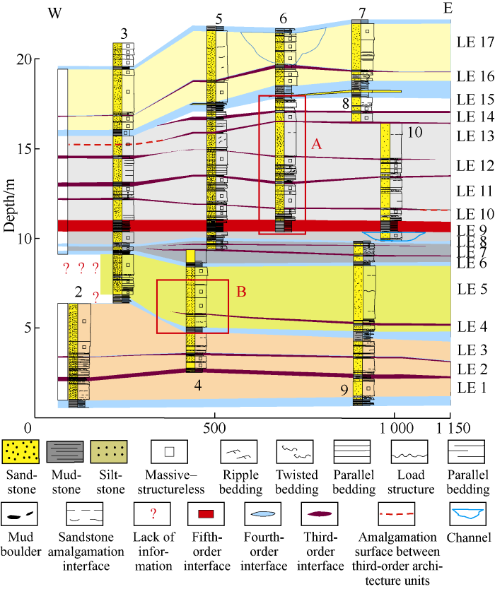
Fig. 3.
Characteristics of 17 third-order architecture units (LE1-LE 17) and 3rd-order, 4th-order and 5th-order architecture interfaces in the study area.
Slide-slump: composed of lithofacies (7), only exposes locally in the study area, indicating a local steep slope and unstable environment. Slide-slump deposits have strong erosion and reworking influence on the underlying strata, adding difficulties to regional stratigraphic correlation.
In addition, some researchers have discovered multiple intervals of goniatite-rich shale (facies (1)) in the Clare Basin, with thickness of 0.5 m to 20.0 m[6,7,8,9], which occur continuously in the basin and have important isochronous signifi-cance. Only one layer of 0.7 m of pelagic shale exposes in the study area. With a stable thickness, it is an important marker layer for stratigraphic correlation.
3. Architecture hierarchy
For the architecture hierarchy of deep-water turbidite lobes, researchers have proposed several division schemes based on high-resolution seismic data and outcrop characterization in recent years[10,11,12,13,14,15,16,17,18,19,20]. In this study, with reference to the existing schemes, based on detailed analysis of outcrops and full consideration of turbidite lobe sedimentary model, scale of architecture units, top and bottom interfaces and internal characteristics, a seven-order division scheme from laminae to turbidity system is proposed (Table 1).
Table 1 Comparison of division schemes of turbidity lobe architecture.
| Scheme | Scheme in literature [11, 14] | Scheme in literature [17] | Scheme in literature [18] | Scheme in literature [19] | Scheme in literature [20] | Scheme in literature [12-15] |
|---|---|---|---|---|---|---|
| 7th-order turbidite system | Non | Non | Non | Submarine fan complex | Fan complex | Non |
| 6th-order submarine fan | Non | Non | Non | Single submarine fan, lobe complex | Individual fan | Non |
| 5th-order lobe complex | Lobe complex | Non | Non | Composite lobe | The stage of fan development | Lobe complex |
| 4th-order lobe | Lobe systema, lobe | Non | lobe complex | Singe lobe | Lobe | Lobe, composite lobed |
| 3rd-order lobe | Lobe element | Lobe element | Lobe element, lobe storeyc | Certain sedimentary interval within a single lobe | Lithofacies and bedding patterns | Lobe element |
| 2nd-order single sandstone bed | Single sandstone layer/ single sandstone bed-setsb | Single sand- stone layer | Single sand- stone layer | Certain rhythm unit within the sedimentary interval | Non | Single sandstone layer |
| 1st-order Laminae | Non | Non | Non | Non | Non | Non |
Note: a—Lobe system; b—Bed-set; c—Lobe storey; d—Composite lobe.
The hierarchical architectural units of fluvial facies and turbidite channel facies usually have evident irregular physical interfaces, such as large scouring surfaces. In the current outcrop study, the physical interface of turbidite lobe architecture unit is not evident, and the division of architecture hierarchy is based on the identification of muddy units between architecture units.
In this study, a total of two fifth-order architecture units, six fourth-order architecture units, and seventeen third-order architecture units have been identified (Figs. 3 and 4). The interface between fifth-order architecture units is a 0.7 m-thick, goniatite-rich pelagic shale (Fig. 2a), which suggests a sedimentary hiatus of about 1×10⁵-1×10⁶ years according to the rate of suspension settlement[6,7,8,9]. The fifth-order lobe complex is the highest-order architecture unit in this study. The top interface of the upper lobe complex and the bottom interface of the lower lobe complex are not exposed in the study area. The fifth-order architecture unit is composed of multiple lobes (fourth-order). The interfaces between the fourth-order architecture units are laminated shale sections of 0.25-1.00 m thick, occasionally intercalated with siltstone interlayers. The top and bottom surfaces of the shale sections are rarely eroded and scoured (Figs. 2b, 3 and 4). The fourth-order interfaces in the study area are stably distributed laterally to several kilometers across (Figs. 3 and 5), indicating sedimentary hiatus caused by the diversion of large supply channels.
Within the fourth-order lobe, there are multiple shale intervals, with a thickness of 0.02 m to 0.50 m with a lateral distribution of several hundred meters to several thousand meters, intercalated with thin layers of siltstone (Figs. 3 and 5). These shale intervals indicate the depositional hiatus between the lobe elements, and are the interfaces of the lobe elements (third-order) (Fig. 5c, 5d). One lobe element is composed of multiple single sandstone layers (second-order), shale intercalations with a large variation in thickness (0.01-0.30 m) and lateral extension from several to hundreds of meters occur between the sandstone layers. Each single sandstone layer indicates a turbidity current deposition event, and the depositional time may be only a few seconds to several days. Due to the rapid depositional rate, the muddy components of turbidity flow were eroded by the turbidity flow in the new stage before fully settled. The shale intervals between single sandstone layers are generally thin, poor in continuity and frequently pinch out abruptly. Sand-body amalgamation frequently appears, massive sandstone layers with a thickness greater than 3 m can be formed by amalgamation of multi-phase sand bodies.
Fig. 5.

Fig. 5.
2-5 order architecture units and interfaces in the study area. c and d sections are located near the observation points of 4, 9 respectively, about 800 m from each other, and the fourth-order interface E is stable in distribution; e and f sections are located near the observation points 5 and 8 about 600 m from each other, and the fourth-order interface B is stably distributed.
Vertically, the most evident architectural characteristics of turbidite lobes are the parallel/subparallel interbedding of coarse-grained/sandy, thick-layered units and fine-grained/ muddy, thin-layered interfaces. The architecture interfaces of all hierarchical levels are the main flow barriers of corresponding architecture units. To identify accurately the muddy architecture interfaces at different levels is the key to dividing the hierarchical levels and study the distribution pattern and connectivity of sand-bodies. The turbidite lobe architecture units generally have a flat bottom and convex top shape on vertical profile. Due to the relatively large width to thickness ratio (usually greater than 500:1)[21,22,23,24], the “bulge” at the top interface is not evident, instead, it shows horizontal and tabular characteristics, with occasional erosion and scouring structures.
4. Quantitative characterization of turbidite lobe sand bodies
Lateral fringes of the two fifth-order architecture units are not exposed in the study area, but previous studies[6,7,8,9] have shown that they are stably distributed in the study area, with lateral distribution range expected to be tens of kilometers and maximum thicknesses of about 70-200 m. The outcrop can provide high-resolution vertical data, but the study on lateral pinching-out characteristics of architecture units is heavily dependent on the quality and range of outcrop. Previous studies have shown that the provenance direction for the study area was perpendicular to the strike of the outcrop[6,7,8,9]. The width can be approximated as the true width, which can avoid errors caused by the measurement angle. However, the lateral pinch-out interfaces of fourth-order and third-order architecture units are not observed in this study area. Meanwhile, second-order architecture units are highly amalgamated and abrupt pinching-out often appears (Figs. 3 and 4). This study cannot accurately record the width value of each architecture unit, but can only estimate the width range based on previous studies.
Table 2 Quantitative architecture characteristics of turbidite lobes.
| Architecture unit | Width | Thickness/ m | Characteristics | Architecture interface | Width | Thickness/ m | Characteristics |
|---|---|---|---|---|---|---|---|
| Fifth-order architecture Unit | tens of kilometers | 70-200 | Lobate shape on the plane; vertically parallel/subparallel sand-mud interbedded layers; no amalgamation | Fifth-order architecture interface | tens of kilometers | 0.5-20.0 | Organic-rich pelagic shale; excellent preservation; depositional time of 1×10⁵-1×10⁶ years |
| Fourth-order architecture Unit | thousands of meters | 0.6-7.1, 3.1 on average | Lobate shape on the plane; compensational overlapping vertically; low degree of amalgamation | Fourth-order architecture interface | thousands of meters | 0.25-1.00 | Laminated mudstone with thin- layered siltstone/fine sandstone; good preservation; depositional time of 10-14 ka |
| Third-order architecture unit | hundreds to thousands of meters | 0.45-3.10, 1.90 on average | Lobate shape on the plane; vertically thickening-upward characteristics; moderate degree of amalgamation | Third-order architecture interface | hundreds to thousands of meters | 0.02-0.50 | Laminated mudstone with thin siltstone/fine sandstone; average preservation; depositional time of 0.5-5.0 ka |
| Second-order architecture Unit | hundreds to thousands of meters | 0.02-3.00, 0.32 on average | Vertically parallel/ sub-parallel stacking; high degree of amalgamation | Second-order architecture interface | hundreds to thousands of meters | 0.01-0.30 | Mudstone with thin-layered siltstone; poor preservation; depositional time from seconds to tens of days |
Fig. 6.
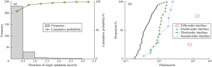
Fig. 6.
Thickness distribution of single sandstone layer in study area (a) and thickness statistics of second-order to fifth-order architecture units (b).
The six lobes (fourth-order) vary greatly in maximum thickness and have an average thickness of 3.17 m. The number of lobe elements (third-order) within a single lobe varies greatly. For example, lobe No.5 has six lobe elements, while in lobe No.4, there is only one lobe element (Fig. 3). In addition, the lobe elements vary greatly in width and can amalgamate with each other (lobe element amalgamation, Fig. 3). The lobe elements have an average thickness of 1.34 m.
The second-order architecture units vary greatly in thickness (0.02-3.00 m), and range from several meters to hundreds of meters wide. Statistical data of more than 280 single sandstone layers from ten observation points show that the single sandstone layers are 0.32 m thick on average (median of 0.15 m), and the thickness of most single sandstone beds fall into the range of 0.05-0.50 m (Fig. 6a). The sandstone layers can be up to 3 m thick or more, which could be developed in the central part of the turbidity lobe, and may be formed through amalgamation of multiple thin single sandstone layers. Lateral tracing of the outcrop shows that the thick sandstone layers become thinner towards both sides laterally, and often split into multiple thin sandstone layers intercalated with shale layers.
5. Discussion
5.1. Sedimentary model of turbidite lobe
A detailed stratigraphic correlation in the study area shows that within the two fifth-order architecture units, from old to new, the fourth-order architecture units show a gradually decreasing trend in thickness (lobe No. 1-4; lobe No. 5-6, see Figs. 3 and 4), which may reflect the continuous increase in the ratio of accommodation/sediment supply (A/S) until the termination of deposition. In addition, adjacent lobes show the characteristics of compensational stacking, namely, the thickest position (proximal environment) of overlying lobe generally occur on top of the thinnest position (distal environment) of the underlying lobe (Fig. 4). Because new turbidity events always tend to fill in the lower terrain formed by the deposition of old turbidity events, thereby continuously compensating the existing terrain. After continuous compensational filling, the final sediments show parallel, tabular characteristics, namely the “turbidite sheets” described by previous researchers. The muddy units between adjacent lobes are stable, with rare erosion and scouring structures (Figs. 3, 4 and 5), indicating a low-energy sedimentary environment, also suggesting that the vertical stacking of lobes is dominated by compensational stacking.
Fig. 4.
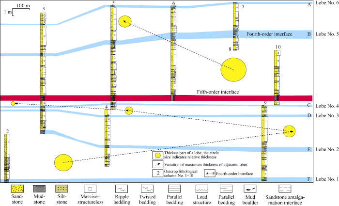
Fig. 4.
Compensatory overlapping characteristics of lobes in the study area.
The seventeen lobe elements identified in this study (third- order architecture unit) all show characteristics of thickening-upward cycle vertically (Figs. 2d and 7), and consist of three parts (Figs. 2 and 8), thin-layered shale at the bottom (facies (2)), thin interbedded sandstone and mudstone in the middle (facies (3)), and thick-layered massive sandstone at the top (facies (4)). Therefore, the lobes (fourth-order) appear vertically as repeated overlapping of multiple thickening-upward cycles (third-order) (Figs. 7d and 8), which is consistent with the understanding on turbidity lobes by sedimentologists for decades[17-18, 20]. While thickening upward, the lobe elements also increase in sand content, sandstone amalgamation degree, and erosion degree upward, indicating that, from bottom to top, from old to new, the flow energy increases continuously due to continuous progradation within the lobe.
It should be noted that the vertical thickening-upward cycles only occur at the level of lobe element (third-order architecture unit). When a lobe (fourth-order architecture unit) is composed of multiple lobe elements, the overall vertical stacking of single sandstone beds within the lobe does not display a specific trend, and it does not necessarily display a thickening- upward pattern (Fig. 8), this should be noted in practical work.
Fig. 8.
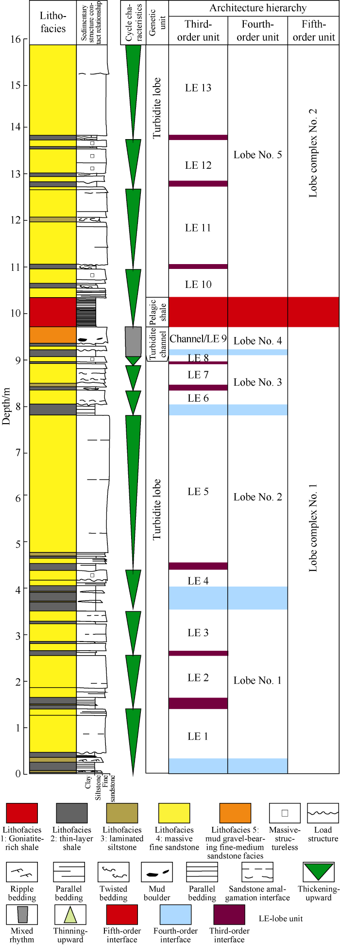
Fig. 8.
Composite column of typical outcrop in the study area (See the position in
Architecture units at all orders have lobate plane shape (Fig. 7b). Taking the lobe as an example, at the turbidite channel mouth or below the channel-lobe transition zone, the sand-rich gravity flows quickly spread around, and the fluid volume and fluid velocity decrease radially from the center to the fringe. Correspondingly, turbidite lobe sediments are characterized by thick sandstone, thin-interbedded sandstone and mudstone, and thick shale from proximal, medial, and distal fringes, respectively. The degree of sandstone amalgamation and net-to-gross ratio gradually decrease. The mud content continues to increase, and the continuity and preservation degree of mudstones increase gradually.
Fig. 7.

Fig. 7.
Architecture units and interfaces of various hierarchical levels in a typical outcrop. The outcrop is a step-like cliff, there is a certain difference between b and c due to the angle of the shot angle; the profile position is in
The third-order lobe elements usually show thickening- upward cycles (Fig. 9), with a special kind of scour structure observed on the top (the top surface of the uppermost massive sandstone) (Fig. 9e, 9g), namely megaflute[6,7]. The explanation to this in this paper is: the turbidity flow passed through channel and continued to advance to the distal region; after unloading the sedimentary lobe element (thickening-upward cycle), the channel was diverted due to the dynamic change of sediment- topography. Below the mouth of new channel, the gravity flow was released to a gentle terrain and hence experienced a sudden acceleration. Correspondingly, at a position close to the new supply channel, high-speed gravity flow scoured old sediments, resulting in the formation of megaflute (Fig. 9e, 9g). Afterwards, as the turbidity continued to accumulate, a new thickening-upward cycle was formed above the megaflute.
Fig. 9.
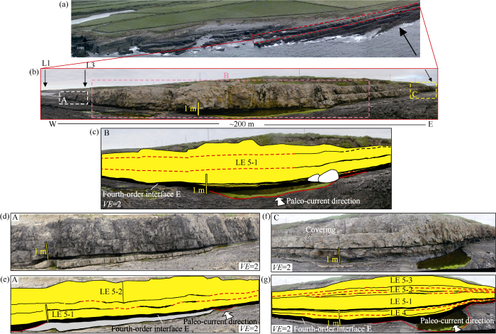
Fig. 9.
Lateral amalgamation characteristics of sandstone layers in typical outcrop (See the position in
The third-order architecture interfaces are lower in preservation degree than the fourth-order architecture interfaces, and the former can be locally eroded. For example, lobe elements LE10 and LE11 in the lobe No. 5 amalgamate with each other (Fig. 10). The incised surface of the upper LE11 to the lower LE10 is only 0.2 m thick and the two stages of sand-bodies are consistent in grain size, which belongs to the Type (4) amalgamation surface[22]. It means that the deposition period between the sand-bodies was extremely short. LE11 is stable in the study area, with vertically thickening-upward characteristics. Its top and bottom surfaces are parallel and tabular, with width greater than 1 km, showing significant differences from the deposits of distributary channels with evident incised surfaces and a width of hundreds of meters, and showing differences from the megaflute too. The amalgamation of lobe bodies causes direct contact of adjacent sand-bodies which form an important flow channel. Also, such amalgamation could make the lobe elements appear local thinning-upward or random vertical stacking pattern. In this study, the amalgamation between the lobe elements was regarded as a special erosion feature, and attention should be paid to this phenomenon.
Fig. 10.

Fig. 10.
Amalgamation phenomenon of the lobe elements inside Lobe No. 5.
5.2. Architecture and connectivity of sand-bodies
Previous studies on outcrops of turbidite lobes[11, 14, 23] showed that in the proximal part of the lobes (fourth-order architecture unit), erosion and scouring structures (channel-lobe transition zone) develop. The fourth-order architecture interfaces might be eroded locally, resulting in the amalgamation between the fourth-order architecture units (similar to the incision and superposition of fluvial channel). The fourth-order architecture interfaces identified in this study are stable. The six fourth-order architecture units are all separated by stably distributed shale layers, and are not connected with each other. The third-order architecture units are lower in preservation degree, and two lobe elements (third-order) are found directly connected in the study area. Within the lobe element, the second-order architecture interfaces are even poorer in preservation degree, and frequent amalgamation occurs between single sand layers.
The sandstone amalgamation surface is not a simply continuous surface. In the lobe element No.5, the LE5-1 interval at the bottom changes from 0.6 m thick (Fig. 9d, 9e) to 2 m thick from west to east, and suddenly splits eastward into a thin sand-mud unit with three sandstone layers intercalated with two mudstone beds (Fig. 9c). It then turns eastward to a 1 m thick sandstone layer (Fig. 9g). The LE5-2 interval has changed from a 1 m thick sandstone from west to east to interbedded sandstone and mudstone unit (Fig. 9d, 9g). In the situation of frequent and discontinuous sandstone amalgamation, the thin mudstone layers are discontinuous in lateral distribution, and have abrupt pinch-out frequently. Overall, the higher the hierarchical order, the lower the degree of amalgamation between the architecture units, and the more complete and continuous the architecture interface is, this is consistent with the previous statistical analysis of the global turbidity lobes[18, 22].
Anatomy of outcrop architecture suggests that, in the vertical profile, turbidite lobes appear as sand-rich architecture units separated by mud-rich architecture interfaces at all orders, and the latter become the flow barrier of the former. These muddy architecture interfaces are thin, generally in the centimeter- meter level, and difficult to identify on the seismic profile. Controlled by multi-order architecture hierarchies, they are extremely complex in distribution and large in lateral distribution range. Quantitatively recording the distribution characteristics of muddy interlayers at different orders and characterizing them in details in stochastic reservoir modeling have been hot spots in recent years in the field of deep-water sedimentology and deep-water reservoir modeling[24,25,26]. Recent studies about reservoir modeling[22] have shown that sandstone amalgamation ratio can quantitatively describe the degree of amalgamation between single sandstone layers, and is the most important factor controlling sandstone connectivity. Similarly, the same method can be used to quantitatively characterize the contact relationship between sand-bodies of higher- order hierarchies, such as the lobe element amalgamation ratio and the lobe amalgamation ratio. They can be defined as the percentages of the length of adjacent lobe elements/lobes amalgamating with each other to the total length of them. In the horizontal direction, architecture units at all hierarchical levels of turbidite lobes have better continuity and good connectivity. In the vertical direction, the turbidite lobes have fast facies transition and poor connectivity. In general, they have stronger vertical heterogeneity than lateral heterogeneity, and poorer vertical connectivity than horizontal connectivity.
6. Conclusions
Through detailed anatomy of the turbidite lobe outcrops in the Carboniferous Ross Sandstone Formation in Ireland, seven types of lithofacies have been identified in the study area, including goniatite-rich pelagic shale, thin laminated shale, laminated siltstone, structureless fine-grained sandstone, mud-clast bearing fine-medium sandstone, basal gravel, and chaotic mudstones. Three genetic units have been divided, including turbidite lobe, turbidite channel, and slide-slump. A seven-order architecture hierarchy from turbidite system to laminae in deep-water turbidite has been proposed. The outcrop in the study area can be divided into four architecture hierarchies, including lobe complex, lobe, lobe element and single sandstone layer. The architecture units at each hierarchical level and the corresponding architecture interfaces have completely different characteristics, among which the lobes show characteristics of evident compensational stacking, and the lobe elements show thickening-upward cycle. There are frequent amalgamations between single sandstone layers. In general, the turbidite lobe deposits appear as tabular, parallel/sub-parallel sandstone with mudstone interbeds. Turbidite lobe deposits transit from thick, massive sandstones with high net-to-gross ratio and amalgamation ratio at the proximal region into thin sandstones interbedded with mudstones with low net-to-gross ratio and sandstone amalgamation ratio towards distal fringes both laterally and longitudinally.
Reference
Global overview of deep- water exploration and production. Atlas of Deep-Water Outcrops: AAPG Studies in
Submarine transitional flow deposits in the Paleogene Gulf of Mexico
Turbidite channel reservoirs: Key elements in facies prediction and effective development
Architectural elements and growth patterns of submarine channels: Application to hydrocarbon exploration
Turbidites in the Upper Carboniferous Ross Formation, western Ireland: Reconstruction of a channel and spillover system
DOI:10.1046/j.1365-3091.2003.00541.x URL [Cited within: 6]
Megaflute erosion surfaces and the initiation of turbidite channels
DOI:10.1130/0091-7613(2000)28<119:MESATI>2.0.CO;2 URL [Cited within: 6]
Architectural elements in a ponded submarine fan, Carboniferous Ross Sandstone, western Ireland. Atlas of Deep-water Outcrops: AAPG Studies in
Multiscale stratigraphic analysis of a structurally confined submarine fan: Carboniferous Ross Sandstone, Ireland
DOI:10.1306/01110807042 URL [Cited within: 6]
Subsurface reservoir architecture characterization: Current status and prospects
Evolution, architecture and hierarchy of distributary deep-water deposits: A high-resolution outcrop investigation from the Permian Karoo Basin, South Africa
DOI:10.1111/sed.2009.56.issue-7 URL [Cited within: 2]
Sediment distribution and evolution of sedimentary processes in a small sandy turbidite system(Golo system, Mediterranean Sea): Implications for various geometries based on core framework
DOI:10.1007/s00367-006-0045-z
URL
[Cited within: 1]

The Golo Margin in eastern Corsica is dissected by four canyons and two gullies which fed turbidite systems. Study of the dispersal of surficial sediments and flow dynamic in the Golo system is based on Kullenberg and interface cores interpreted in relation to a previously published seismic dataset. Cores were described in detail and interpreted within a sedimentary and stratigraphic framework. During the last 42,000 years, gravity processes which occurred in the large systems with a canyon source were mainly slide-induced, differentiated turbulent surges and hyperpycnal flows. Processes occurring in the small system with a gully source are mainly hyperconcentrated and concentrated flows. Deposits from the Corsican Margin can intercalate with products of processes triggered on the Pianosa Ridge located in the eastern part of the basin. During relative sea-level lowstands or during periods of rapid or high-amplitude sea-level fall, only large canyons (South and North Golo) are supplied by carbonate-rich hyperconcentrated and concentrated flows which are channelled in incised valleys on the shelf. During periods of slow or low-amplitude sea-level fall and during sea-level rise, sediments are trapped on a shelf delta and intensely winnowed by shelf hydrodynamic processes. Sand-rich hyperconcentrated and concentrated flows occur. All the systems fed by a canyon are active simultaneously. Gullies form and are active only during periods of sea-level rise. During relative highstands of sea level (Holocene), all the system is draped by hemipelagic sediments. Relative sea-level changes and canyon location relative to river mouths have a strong influence on the nature of sediment input, and the initiation and type of gravity flows which, in turn, control morphology and geometry.
Dimensions and architecture of late Pleistocene submarine lobes off the northern margin of East Corsica
DOI:10.1111/j.1365-3091.2007.00926.x URL [Cited within: 1]
Depositional architecture and evolution of progradationally stacked lobe complexes in the Eocene Central Basin of Spitsbergen
DOI:10.1111/sed.12067
URL
[Cited within: 2]
The down-dip portion of submarine fans comprises terminal lobes that consist of various gravity flow deposits, including turbidites and debrites. Within lobe complexes, lobe deposition commonly takes place in topographic lows created between previous lobes, resulting in an architecture characterized by compensational stacking. However, in some deep water turbidite systems, compensational stacking is less prominent and progradation dominates over aggradation and lateral stacking. Combined outcrop and subsurface data from the Eocene Central Basin of Spitsbergen provide a rare example of submarine fans that comprise progradationally stacked lobes and lobe complexes. Evidence for progradation includes basinward offset stacking of successive lobe complexes, a vertical change from distal to proximal lobe environments as recorded by an upward increase in bed amalgamation, and coarsening and thickening upward trends within the lobes. Slope clinoforms occur immediately above the lobe complexes, suggesting that a shelf-slope system prograded across the basin in concert with deposition of the lobe complexes. Erosive channels are present in proximal axial lobe settings, whereas shallow channels, scours and terminal lobes dominate further basinward. Terminal lobes are classified as amalgamated, non-amalgamated or thin-bedded, consistent with turbidite deposition in lobe axis, off-axis and fringe settings, respectively. Co-genetic turbidite-debrite beds, interpreted as being deposited from hybrid sediment gravity flows which consisted of both turbulent and laminar flow phases, occur frequently in lobe off-axis to fringe settings, and are rare and poorly developed in channels and axial lobe environments. This indicates bypass of the laminar flow phase in proximal settings, and deposition in relative distal unconfined settings. Palaeocurrent data indicate sediment dispersal mainly towards the east, and is consistent with slope and lobe complex progradation perpendicular to the NNW-SSE trending basin margin.
Channel-mouth lobe complex of the recent Amazon Fan: The missing piece
DOI:10.1016/j.margeo.2008.03.004 URL [Cited within: 1]
Characteristics of Pleistocene deep-water fan lobes and their application to an upper Miocene reservoir model, offshore East Kalimantan, Indonesia
DOI:10.1306/03310807110 URL [Cited within: 1]
Sedimentation in deep-sea lobe-elements: Implications for the origin of thickening-upward sequences
DOI:10.1144/0016-76492010-036 URL [Cited within: 2]
Quantifying the hierarchical organization of compensation in submarine fans using surface statistics
DOI:10.2110/jsr.2012.73 URL [Cited within: 3]
Research on reservoir architecture models of deep-water turbidite lobes
DOI:10.11764/j.issn.1672-1926.2014.08.1197
URL
[Cited within: 1]
Comparing examples of modern and ancient turbidite systems: Problems and concepts, in marine clastic sedimentology
Relationships between morphological and sedimentological parameters in source-to-sink systems: A basis for predicting semi-quantitative characteristics in subsurface systems
DOI:10.1111/bre.2009.21.issue-4 URL [Cited within: 1]
Quantitative characteristics of sandstone amalgamation and its impact on reservoir connectivity
DOI:10.1016/S1876-3804(17)30025-3 URL [Cited within: 4]
Stratigraphic evolution of fine-grained submarine fan systems, Tanqua Depocenter, Karoo Basin, South Africa
DOI:10.2110/jsr.2006.03 URL [Cited within: 2]
Outcrop-based stochastic modeling of turbidite amalgamation and its effects on hydrocarbon recovery
DOI:10.1144/petgeo.7.2.163 URL [Cited within: 2]
Three-dimensional modeling of a shoreface-shelf parasequence reservoir analog: Part 1. surface-based modeling to capture high-resolution facies architecture
DOI:10.1306/05110908144 URL [Cited within: 1]
Preliminary study on a depositional interface-based reservoir modeling method
