A new transient matrix/fracture shape factor for capillary and gravity imbibition in fractured reservoirs
1
2015
... The naturally fractured reservoir can be simplified as a system combined by matrix blocks and fractures[1]. For simplicity, the matrix blocks are considered as cuboids of different dimensions. The shapes and dimensions of the matrix blocks depend on the density and direction of fractures[2,3]. ...
Reservoir engineering of fractured reservoirs: Fundamental and practical aspects
1
1987
... The naturally fractured reservoir can be simplified as a system combined by matrix blocks and fractures[1]. For simplicity, the matrix blocks are considered as cuboids of different dimensions. The shapes and dimensions of the matrix blocks depend on the density and direction of fractures[2,3]. ...
1
1982
... The naturally fractured reservoir can be simplified as a system combined by matrix blocks and fractures[1]. For simplicity, the matrix blocks are considered as cuboids of different dimensions. The shapes and dimensions of the matrix blocks depend on the density and direction of fractures[2,3]. ...
Global importance of “continuous” petroleum reservoirs: Accumulation, distribution and evaluation
1
2009
... As the production of a fractured reservoir goes on, the gas-oil contact in it starts dropping. The gas with high mobility overtakes the oil in the matrix blocks through the fractures and traps the oil in the matrix blocks. Due to gravity, oil would drain out from a matrix block. But under the joint effect of gravity and capillary force, the oil would re-infiltrate into the matrix block below the former matrix block[4,5,6,7,8]. ...
Models of steam-assisted gravity drainage (SAGD) steam chamber expanding velocity in double horizontal wells and its application
1
2019
... As the production of a fractured reservoir goes on, the gas-oil contact in it starts dropping. The gas with high mobility overtakes the oil in the matrix blocks through the fractures and traps the oil in the matrix blocks. Due to gravity, oil would drain out from a matrix block. But under the joint effect of gravity and capillary force, the oil would re-infiltrate into the matrix block below the former matrix block[4,5,6,7,8]. ...
Mathematical simulation of fractured reservoir performance, based on physical model experiments
1
1979
... As the production of a fractured reservoir goes on, the gas-oil contact in it starts dropping. The gas with high mobility overtakes the oil in the matrix blocks through the fractures and traps the oil in the matrix blocks. Due to gravity, oil would drain out from a matrix block. But under the joint effect of gravity and capillary force, the oil would re-infiltrate into the matrix block below the former matrix block[4,5,6,7,8]. ...
Investigation of gravity drainage in fractured porous media using rectangular macromodels
1
2008
... As the production of a fractured reservoir goes on, the gas-oil contact in it starts dropping. The gas with high mobility overtakes the oil in the matrix blocks through the fractures and traps the oil in the matrix blocks. Due to gravity, oil would drain out from a matrix block. But under the joint effect of gravity and capillary force, the oil would re-infiltrate into the matrix block below the former matrix block[4,5,6,7,8]. ...
Block to block interaction effect in naturally fractured reservoirs
1
2006
... As the production of a fractured reservoir goes on, the gas-oil contact in it starts dropping. The gas with high mobility overtakes the oil in the matrix blocks through the fractures and traps the oil in the matrix blocks. Due to gravity, oil would drain out from a matrix block. But under the joint effect of gravity and capillary force, the oil would re-infiltrate into the matrix block below the former matrix block[4,5,6,7,8]. ...
Reinfiltration through liquid bridges formed between two matrix blocks in fractured rocks
1
2014
... Interaction between matrix blocks can give rise to reinfiltration and capillary continuity[9]. The reinfiltration is the reimbibition of oil from the fracture into the matrix block. The capillary continuity occurs when oil moves from one matrix block to another through a liquid bridge between fractures[10]. ...
Quantifying the reimbibition effect on the performance of gas-oil gravity drainage in fractured reservoirs: Mathematical modelling
1
2019
... Interaction between matrix blocks can give rise to reinfiltration and capillary continuity[9]. The reinfiltration is the reimbibition of oil from the fracture into the matrix block. The capillary continuity occurs when oil moves from one matrix block to another through a liquid bridge between fractures[10]. ...
Wetting phase bridges establish capillary continuity across open fractures and increase oil recovery in mixed-wet fractured chalk
1
2008
... Aspenes et al. conducted a series of experiments on the capillary continuity mechanism. They found that in the case of noticeable capillary continuity, oil movement towards producing well took place in the matrix block network instead of the high permeable fractures[11]. Labastie claimed that the oil recovery of naturally fractured reservoirs strongly depended on capillary continuity[12]. Horie et al. evaluated the effect of capillary continuity on the recovery of a stack of matrix blocks through some experiments[13]. Sajadian et al. introduced the critical fracture aperture to characterize the effective capillary continuity[14]. Miri et al. developed a mathematical model to predict the critical fracture aperture[15]. Harimi et al. studied the effects of fracture roughness and frequency on the capillary continuity theoretically[16]. Mashayekhizadeh et al. investigated the stability of liquid bridges formed between fractures at different fracture apertures and dip angles by some experiments using glass micromodels[17,18]. Stones et al. found through experiments that a reduction of the liquid surface tension would reduce the effect of fracture on the ultimate recovery[19]. Dejam et al. developed a mechanistic model for formation, growth, and detachment of horizontal liquid bridges between matrix blocks[20,21] and proposed two dimensionless parameters to describe the shape of the liquid bridge surface[21]. ...
Capillary continuity between blocks of a fractured reservoir
1
1990
... Aspenes et al. conducted a series of experiments on the capillary continuity mechanism. They found that in the case of noticeable capillary continuity, oil movement towards producing well took place in the matrix block network instead of the high permeable fractures[11]. Labastie claimed that the oil recovery of naturally fractured reservoirs strongly depended on capillary continuity[12]. Horie et al. evaluated the effect of capillary continuity on the recovery of a stack of matrix blocks through some experiments[13]. Sajadian et al. introduced the critical fracture aperture to characterize the effective capillary continuity[14]. Miri et al. developed a mathematical model to predict the critical fracture aperture[15]. Harimi et al. studied the effects of fracture roughness and frequency on the capillary continuity theoretically[16]. Mashayekhizadeh et al. investigated the stability of liquid bridges formed between fractures at different fracture apertures and dip angles by some experiments using glass micromodels[17,18]. Stones et al. found through experiments that a reduction of the liquid surface tension would reduce the effect of fracture on the ultimate recovery[19]. Dejam et al. developed a mechanistic model for formation, growth, and detachment of horizontal liquid bridges between matrix blocks[20,21] and proposed two dimensionless parameters to describe the shape of the liquid bridge surface[21]. ...
Laboratory studies of capillary interaction in fracture/matrix systems
1
1990
... Aspenes et al. conducted a series of experiments on the capillary continuity mechanism. They found that in the case of noticeable capillary continuity, oil movement towards producing well took place in the matrix block network instead of the high permeable fractures[11]. Labastie claimed that the oil recovery of naturally fractured reservoirs strongly depended on capillary continuity[12]. Horie et al. evaluated the effect of capillary continuity on the recovery of a stack of matrix blocks through some experiments[13]. Sajadian et al. introduced the critical fracture aperture to characterize the effective capillary continuity[14]. Miri et al. developed a mathematical model to predict the critical fracture aperture[15]. Harimi et al. studied the effects of fracture roughness and frequency on the capillary continuity theoretically[16]. Mashayekhizadeh et al. investigated the stability of liquid bridges formed between fractures at different fracture apertures and dip angles by some experiments using glass micromodels[17,18]. Stones et al. found through experiments that a reduction of the liquid surface tension would reduce the effect of fracture on the ultimate recovery[19]. Dejam et al. developed a mechanistic model for formation, growth, and detachment of horizontal liquid bridges between matrix blocks[20,21] and proposed two dimensionless parameters to describe the shape of the liquid bridge surface[21]. ...
Laboratory studies of gravity drainage mechanism in fractured carbonate reservoir: Capillary continuity
1
1998
... Aspenes et al. conducted a series of experiments on the capillary continuity mechanism. They found that in the case of noticeable capillary continuity, oil movement towards producing well took place in the matrix block network instead of the high permeable fractures[11]. Labastie claimed that the oil recovery of naturally fractured reservoirs strongly depended on capillary continuity[12]. Horie et al. evaluated the effect of capillary continuity on the recovery of a stack of matrix blocks through some experiments[13]. Sajadian et al. introduced the critical fracture aperture to characterize the effective capillary continuity[14]. Miri et al. developed a mathematical model to predict the critical fracture aperture[15]. Harimi et al. studied the effects of fracture roughness and frequency on the capillary continuity theoretically[16]. Mashayekhizadeh et al. investigated the stability of liquid bridges formed between fractures at different fracture apertures and dip angles by some experiments using glass micromodels[17,18]. Stones et al. found through experiments that a reduction of the liquid surface tension would reduce the effect of fracture on the ultimate recovery[19]. Dejam et al. developed a mechanistic model for formation, growth, and detachment of horizontal liquid bridges between matrix blocks[20,21] and proposed two dimensionless parameters to describe the shape of the liquid bridge surface[21]. ...
Fracture capillary pressure based on the liquid bridge dynamic stability study
1
2014
... Aspenes et al. conducted a series of experiments on the capillary continuity mechanism. They found that in the case of noticeable capillary continuity, oil movement towards producing well took place in the matrix block network instead of the high permeable fractures[11]. Labastie claimed that the oil recovery of naturally fractured reservoirs strongly depended on capillary continuity[12]. Horie et al. evaluated the effect of capillary continuity on the recovery of a stack of matrix blocks through some experiments[13]. Sajadian et al. introduced the critical fracture aperture to characterize the effective capillary continuity[14]. Miri et al. developed a mathematical model to predict the critical fracture aperture[15]. Harimi et al. studied the effects of fracture roughness and frequency on the capillary continuity theoretically[16]. Mashayekhizadeh et al. investigated the stability of liquid bridges formed between fractures at different fracture apertures and dip angles by some experiments using glass micromodels[17,18]. Stones et al. found through experiments that a reduction of the liquid surface tension would reduce the effect of fracture on the ultimate recovery[19]. Dejam et al. developed a mechanistic model for formation, growth, and detachment of horizontal liquid bridges between matrix blocks[20,21] and proposed two dimensionless parameters to describe the shape of the liquid bridge surface[21]. ...
Modeling of capillary pressure in horizontal rough-walled fractures in the presence of liquid bridges
1
2020
... Aspenes et al. conducted a series of experiments on the capillary continuity mechanism. They found that in the case of noticeable capillary continuity, oil movement towards producing well took place in the matrix block network instead of the high permeable fractures[11]. Labastie claimed that the oil recovery of naturally fractured reservoirs strongly depended on capillary continuity[12]. Horie et al. evaluated the effect of capillary continuity on the recovery of a stack of matrix blocks through some experiments[13]. Sajadian et al. introduced the critical fracture aperture to characterize the effective capillary continuity[14]. Miri et al. developed a mathematical model to predict the critical fracture aperture[15]. Harimi et al. studied the effects of fracture roughness and frequency on the capillary continuity theoretically[16]. Mashayekhizadeh et al. investigated the stability of liquid bridges formed between fractures at different fracture apertures and dip angles by some experiments using glass micromodels[17,18]. Stones et al. found through experiments that a reduction of the liquid surface tension would reduce the effect of fracture on the ultimate recovery[19]. Dejam et al. developed a mechanistic model for formation, growth, and detachment of horizontal liquid bridges between matrix blocks[20,21] and proposed two dimensionless parameters to describe the shape of the liquid bridge surface[21]. ...
Pore-level observation of free gravity drainage of oil in fractured porous media
1
2011
... Aspenes et al. conducted a series of experiments on the capillary continuity mechanism. They found that in the case of noticeable capillary continuity, oil movement towards producing well took place in the matrix block network instead of the high permeable fractures[11]. Labastie claimed that the oil recovery of naturally fractured reservoirs strongly depended on capillary continuity[12]. Horie et al. evaluated the effect of capillary continuity on the recovery of a stack of matrix blocks through some experiments[13]. Sajadian et al. introduced the critical fracture aperture to characterize the effective capillary continuity[14]. Miri et al. developed a mathematical model to predict the critical fracture aperture[15]. Harimi et al. studied the effects of fracture roughness and frequency on the capillary continuity theoretically[16]. Mashayekhizadeh et al. investigated the stability of liquid bridges formed between fractures at different fracture apertures and dip angles by some experiments using glass micromodels[17,18]. Stones et al. found through experiments that a reduction of the liquid surface tension would reduce the effect of fracture on the ultimate recovery[19]. Dejam et al. developed a mechanistic model for formation, growth, and detachment of horizontal liquid bridges between matrix blocks[20,21] and proposed two dimensionless parameters to describe the shape of the liquid bridge surface[21]. ...
An experimental investigation of fracture tilt angle effects on frequency and stability of liquid bridges in fractured porous media
1
2012
... Aspenes et al. conducted a series of experiments on the capillary continuity mechanism. They found that in the case of noticeable capillary continuity, oil movement towards producing well took place in the matrix block network instead of the high permeable fractures[11]. Labastie claimed that the oil recovery of naturally fractured reservoirs strongly depended on capillary continuity[12]. Horie et al. evaluated the effect of capillary continuity on the recovery of a stack of matrix blocks through some experiments[13]. Sajadian et al. introduced the critical fracture aperture to characterize the effective capillary continuity[14]. Miri et al. developed a mathematical model to predict the critical fracture aperture[15]. Harimi et al. studied the effects of fracture roughness and frequency on the capillary continuity theoretically[16]. Mashayekhizadeh et al. investigated the stability of liquid bridges formed between fractures at different fracture apertures and dip angles by some experiments using glass micromodels[17,18]. Stones et al. found through experiments that a reduction of the liquid surface tension would reduce the effect of fracture on the ultimate recovery[19]. Dejam et al. developed a mechanistic model for formation, growth, and detachment of horizontal liquid bridges between matrix blocks[20,21] and proposed two dimensionless parameters to describe the shape of the liquid bridge surface[21]. ...
The effect of capillary connectivity across horizontal fractures on gravity drainage from fractured porous media
1
1992
... Aspenes et al. conducted a series of experiments on the capillary continuity mechanism. They found that in the case of noticeable capillary continuity, oil movement towards producing well took place in the matrix block network instead of the high permeable fractures[11]. Labastie claimed that the oil recovery of naturally fractured reservoirs strongly depended on capillary continuity[12]. Horie et al. evaluated the effect of capillary continuity on the recovery of a stack of matrix blocks through some experiments[13]. Sajadian et al. introduced the critical fracture aperture to characterize the effective capillary continuity[14]. Miri et al. developed a mathematical model to predict the critical fracture aperture[15]. Harimi et al. studied the effects of fracture roughness and frequency on the capillary continuity theoretically[16]. Mashayekhizadeh et al. investigated the stability of liquid bridges formed between fractures at different fracture apertures and dip angles by some experiments using glass micromodels[17,18]. Stones et al. found through experiments that a reduction of the liquid surface tension would reduce the effect of fracture on the ultimate recovery[19]. Dejam et al. developed a mechanistic model for formation, growth, and detachment of horizontal liquid bridges between matrix blocks[20,21] and proposed two dimensionless parameters to describe the shape of the liquid bridge surface[21]. ...
Formation of liquid bridges between porous matrix blocks
1
2011
... Aspenes et al. conducted a series of experiments on the capillary continuity mechanism. They found that in the case of noticeable capillary continuity, oil movement towards producing well took place in the matrix block network instead of the high permeable fractures[11]. Labastie claimed that the oil recovery of naturally fractured reservoirs strongly depended on capillary continuity[12]. Horie et al. evaluated the effect of capillary continuity on the recovery of a stack of matrix blocks through some experiments[13]. Sajadian et al. introduced the critical fracture aperture to characterize the effective capillary continuity[14]. Miri et al. developed a mathematical model to predict the critical fracture aperture[15]. Harimi et al. studied the effects of fracture roughness and frequency on the capillary continuity theoretically[16]. Mashayekhizadeh et al. investigated the stability of liquid bridges formed between fractures at different fracture apertures and dip angles by some experiments using glass micromodels[17,18]. Stones et al. found through experiments that a reduction of the liquid surface tension would reduce the effect of fracture on the ultimate recovery[19]. Dejam et al. developed a mechanistic model for formation, growth, and detachment of horizontal liquid bridges between matrix blocks[20,21] and proposed two dimensionless parameters to describe the shape of the liquid bridge surface[21]. ...
Shape of liquid bridges in a horizontal fracture
2
2014
... Aspenes et al. conducted a series of experiments on the capillary continuity mechanism. They found that in the case of noticeable capillary continuity, oil movement towards producing well took place in the matrix block network instead of the high permeable fractures[11]. Labastie claimed that the oil recovery of naturally fractured reservoirs strongly depended on capillary continuity[12]. Horie et al. evaluated the effect of capillary continuity on the recovery of a stack of matrix blocks through some experiments[13]. Sajadian et al. introduced the critical fracture aperture to characterize the effective capillary continuity[14]. Miri et al. developed a mathematical model to predict the critical fracture aperture[15]. Harimi et al. studied the effects of fracture roughness and frequency on the capillary continuity theoretically[16]. Mashayekhizadeh et al. investigated the stability of liquid bridges formed between fractures at different fracture apertures and dip angles by some experiments using glass micromodels[17,18]. Stones et al. found through experiments that a reduction of the liquid surface tension would reduce the effect of fracture on the ultimate recovery[19]. Dejam et al. developed a mechanistic model for formation, growth, and detachment of horizontal liquid bridges between matrix blocks[20,21] and proposed two dimensionless parameters to describe the shape of the liquid bridge surface[21]. ...
... [21]. ...
Special features of fracture network in Iranian fractured reservoirs
1
2010
... The reinfiltration would slow down the oil movement in the fractured reservoirs and cause a delay in production[22]. Festoy and Van Golf-Racht carried out a fine grid simulation and proved the presence of reinfiltration between two stacked matrix blocks[23]. In a theoretical study, Firoozabadi and Ishimoto found that the matrix block reinfiltration rate was always more than or equal to the drainage rate[24] and the reinfiltration rate across vertical faces of the matrix block varied significantly[25]. Moreover, a grid simulation was performed to find out the slope effect on the reinfiltration[26]. Firoozabadi et al. studied the impact of fracture aperture on the rate of oil drainage across stacked matrix blocks by experiments[27]. Sajjadian et al. sorted out the main parameters affecting the reinfiltration process[28]. Aghabarari et al. numerically simulated the reinfiltration process in 3 stacked matrix blocks to find the effect of different reservoir properties on reinfiltration[29]. After some experiments and numerical simulations, Mollaei et al. related the reinfiltration rate to the horizontal fracture width and the size of the matrix pore-throat[30]. More studies about the reinfiltration and capillary continuity can be found in the literature[31,32,33,34]. ...
Gas gravity drainage in fractured reservoirs through new dual-continuum approach
1
1989
... The reinfiltration would slow down the oil movement in the fractured reservoirs and cause a delay in production[22]. Festoy and Van Golf-Racht carried out a fine grid simulation and proved the presence of reinfiltration between two stacked matrix blocks[23]. In a theoretical study, Firoozabadi and Ishimoto found that the matrix block reinfiltration rate was always more than or equal to the drainage rate[24] and the reinfiltration rate across vertical faces of the matrix block varied significantly[25]. Moreover, a grid simulation was performed to find out the slope effect on the reinfiltration[26]. Firoozabadi et al. studied the impact of fracture aperture on the rate of oil drainage across stacked matrix blocks by experiments[27]. Sajjadian et al. sorted out the main parameters affecting the reinfiltration process[28]. Aghabarari et al. numerically simulated the reinfiltration process in 3 stacked matrix blocks to find the effect of different reservoir properties on reinfiltration[29]. After some experiments and numerical simulations, Mollaei et al. related the reinfiltration rate to the horizontal fracture width and the size of the matrix pore-throat[30]. More studies about the reinfiltration and capillary continuity can be found in the literature[31,32,33,34]. ...
Reinfiltration in fractured porous media: Part 1-One dimensional model
1
1994
... The reinfiltration would slow down the oil movement in the fractured reservoirs and cause a delay in production[22]. Festoy and Van Golf-Racht carried out a fine grid simulation and proved the presence of reinfiltration between two stacked matrix blocks[23]. In a theoretical study, Firoozabadi and Ishimoto found that the matrix block reinfiltration rate was always more than or equal to the drainage rate[24] and the reinfiltration rate across vertical faces of the matrix block varied significantly[25]. Moreover, a grid simulation was performed to find out the slope effect on the reinfiltration[26]. Firoozabadi et al. studied the impact of fracture aperture on the rate of oil drainage across stacked matrix blocks by experiments[27]. Sajjadian et al. sorted out the main parameters affecting the reinfiltration process[28]. Aghabarari et al. numerically simulated the reinfiltration process in 3 stacked matrix blocks to find the effect of different reservoir properties on reinfiltration[29]. After some experiments and numerical simulations, Mollaei et al. related the reinfiltration rate to the horizontal fracture width and the size of the matrix pore-throat[30]. More studies about the reinfiltration and capillary continuity can be found in the literature[31,32,33,34]. ...
Reinfiltration in fractured porous media: Part 2-Two dimensional model
1
1994
... The reinfiltration would slow down the oil movement in the fractured reservoirs and cause a delay in production[22]. Festoy and Van Golf-Racht carried out a fine grid simulation and proved the presence of reinfiltration between two stacked matrix blocks[23]. In a theoretical study, Firoozabadi and Ishimoto found that the matrix block reinfiltration rate was always more than or equal to the drainage rate[24] and the reinfiltration rate across vertical faces of the matrix block varied significantly[25]. Moreover, a grid simulation was performed to find out the slope effect on the reinfiltration[26]. Firoozabadi et al. studied the impact of fracture aperture on the rate of oil drainage across stacked matrix blocks by experiments[27]. Sajjadian et al. sorted out the main parameters affecting the reinfiltration process[28]. Aghabarari et al. numerically simulated the reinfiltration process in 3 stacked matrix blocks to find the effect of different reservoir properties on reinfiltration[29]. After some experiments and numerical simulations, Mollaei et al. related the reinfiltration rate to the horizontal fracture width and the size of the matrix pore-throat[30]. More studies about the reinfiltration and capillary continuity can be found in the literature[31,32,33,34]. ...
Implicit compositional simulation of single-porosity and dual-porosity reservoirs
1
1989
... The reinfiltration would slow down the oil movement in the fractured reservoirs and cause a delay in production[22]. Festoy and Van Golf-Racht carried out a fine grid simulation and proved the presence of reinfiltration between two stacked matrix blocks[23]. In a theoretical study, Firoozabadi and Ishimoto found that the matrix block reinfiltration rate was always more than or equal to the drainage rate[24] and the reinfiltration rate across vertical faces of the matrix block varied significantly[25]. Moreover, a grid simulation was performed to find out the slope effect on the reinfiltration[26]. Firoozabadi et al. studied the impact of fracture aperture on the rate of oil drainage across stacked matrix blocks by experiments[27]. Sajjadian et al. sorted out the main parameters affecting the reinfiltration process[28]. Aghabarari et al. numerically simulated the reinfiltration process in 3 stacked matrix blocks to find the effect of different reservoir properties on reinfiltration[29]. After some experiments and numerical simulations, Mollaei et al. related the reinfiltration rate to the horizontal fracture width and the size of the matrix pore-throat[30]. More studies about the reinfiltration and capillary continuity can be found in the literature[31,32,33,34]. ...
Fracture-liquid transmissibility in fractured porous media
1
1994
... The reinfiltration would slow down the oil movement in the fractured reservoirs and cause a delay in production[22]. Festoy and Van Golf-Racht carried out a fine grid simulation and proved the presence of reinfiltration between two stacked matrix blocks[23]. In a theoretical study, Firoozabadi and Ishimoto found that the matrix block reinfiltration rate was always more than or equal to the drainage rate[24] and the reinfiltration rate across vertical faces of the matrix block varied significantly[25]. Moreover, a grid simulation was performed to find out the slope effect on the reinfiltration[26]. Firoozabadi et al. studied the impact of fracture aperture on the rate of oil drainage across stacked matrix blocks by experiments[27]. Sajjadian et al. sorted out the main parameters affecting the reinfiltration process[28]. Aghabarari et al. numerically simulated the reinfiltration process in 3 stacked matrix blocks to find the effect of different reservoir properties on reinfiltration[29]. After some experiments and numerical simulations, Mollaei et al. related the reinfiltration rate to the horizontal fracture width and the size of the matrix pore-throat[30]. More studies about the reinfiltration and capillary continuity can be found in the literature[31,32,33,34]. ...
Laboratory study of gravity drainage mechanism in fractured carbonate reservoir- reinfiltration
1
1999
... The reinfiltration would slow down the oil movement in the fractured reservoirs and cause a delay in production[22]. Festoy and Van Golf-Racht carried out a fine grid simulation and proved the presence of reinfiltration between two stacked matrix blocks[23]. In a theoretical study, Firoozabadi and Ishimoto found that the matrix block reinfiltration rate was always more than or equal to the drainage rate[24] and the reinfiltration rate across vertical faces of the matrix block varied significantly[25]. Moreover, a grid simulation was performed to find out the slope effect on the reinfiltration[26]. Firoozabadi et al. studied the impact of fracture aperture on the rate of oil drainage across stacked matrix blocks by experiments[27]. Sajjadian et al. sorted out the main parameters affecting the reinfiltration process[28]. Aghabarari et al. numerically simulated the reinfiltration process in 3 stacked matrix blocks to find the effect of different reservoir properties on reinfiltration[29]. After some experiments and numerical simulations, Mollaei et al. related the reinfiltration rate to the horizontal fracture width and the size of the matrix pore-throat[30]. More studies about the reinfiltration and capillary continuity can be found in the literature[31,32,33,34]. ...
A new simulation approach to investigate reinfiltration phenomenon in fractured porous media
3
2019
... The reinfiltration would slow down the oil movement in the fractured reservoirs and cause a delay in production[22]. Festoy and Van Golf-Racht carried out a fine grid simulation and proved the presence of reinfiltration between two stacked matrix blocks[23]. In a theoretical study, Firoozabadi and Ishimoto found that the matrix block reinfiltration rate was always more than or equal to the drainage rate[24] and the reinfiltration rate across vertical faces of the matrix block varied significantly[25]. Moreover, a grid simulation was performed to find out the slope effect on the reinfiltration[26]. Firoozabadi et al. studied the impact of fracture aperture on the rate of oil drainage across stacked matrix blocks by experiments[27]. Sajjadian et al. sorted out the main parameters affecting the reinfiltration process[28]. Aghabarari et al. numerically simulated the reinfiltration process in 3 stacked matrix blocks to find the effect of different reservoir properties on reinfiltration[29]. After some experiments and numerical simulations, Mollaei et al. related the reinfiltration rate to the horizontal fracture width and the size of the matrix pore-throat[30]. More studies about the reinfiltration and capillary continuity can be found in the literature[31,32,33,34]. ...
... The inspectional analysis was used to find a new scaling equation[56,57,58,59,60]. First, one needs to determine the governing equation of flow for the reinfiltration mechanism, in which all parameters affecting the fractured reservoir such as permeability-porosity, matrix block cross-sectional area, rock type, fluid type, and matrix block height[29], as well as the effect of capillary pressure, gravity, and viscous forces must be taken into account. Thus, the one-dimensional flow equation in multiple phase flow for oil which is the fundamental equation in reservoir simulation[61] was used in this study: ...
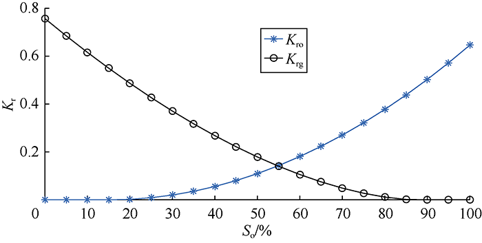
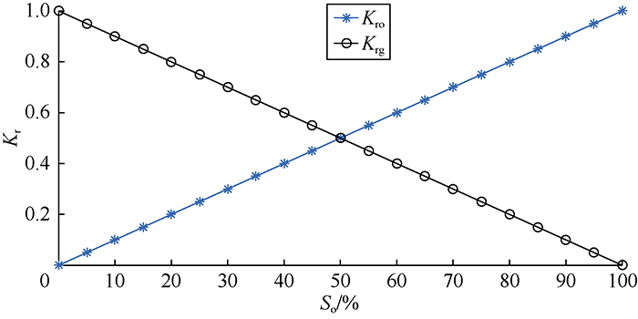
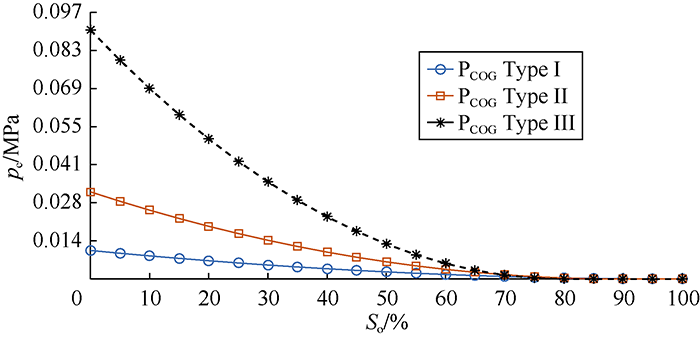
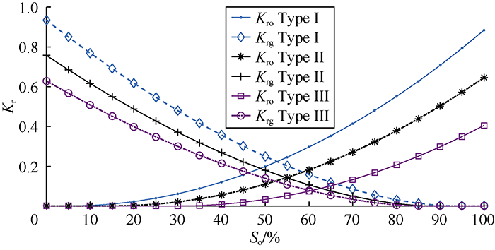
... Through a numerical simulation, Aghabarari et al. sorted out the parameters affecting reinfiltration. Theses parameters in descending order of importance are permeability, porosity, matrix block cross-sectional area, rock type, fluid type, and matrix block height[29]. To check the applicability of the introduced dimensionless equation (Equation 12), various cases were defined, and the ranges of the parameters were defined to characterize different types of naturally fractured reservoirs. By use of Corey correlation of oil and gas[63], three types of rocks (i.e. Types I, II, and III) were defined. These rock types have different connate water saturations, capillary pressures, and relative permeability curves according to Fig. 5 and Fig. 6. Rock type I has the lowest oil wettability while rock type III is highly oil-wet. The characteristics of fluids in the three types of reservoirs are shown in Table 1. Here oils are defined as type I to III in ascending order of density. ...
Free-fall gravity drainage in fractured matrix blocks: Experimental and network modeling simulation findings and observations
1
2007
... The reinfiltration would slow down the oil movement in the fractured reservoirs and cause a delay in production[22]. Festoy and Van Golf-Racht carried out a fine grid simulation and proved the presence of reinfiltration between two stacked matrix blocks[23]. In a theoretical study, Firoozabadi and Ishimoto found that the matrix block reinfiltration rate was always more than or equal to the drainage rate[24] and the reinfiltration rate across vertical faces of the matrix block varied significantly[25]. Moreover, a grid simulation was performed to find out the slope effect on the reinfiltration[26]. Firoozabadi et al. studied the impact of fracture aperture on the rate of oil drainage across stacked matrix blocks by experiments[27]. Sajjadian et al. sorted out the main parameters affecting the reinfiltration process[28]. Aghabarari et al. numerically simulated the reinfiltration process in 3 stacked matrix blocks to find the effect of different reservoir properties on reinfiltration[29]. After some experiments and numerical simulations, Mollaei et al. related the reinfiltration rate to the horizontal fracture width and the size of the matrix pore-throat[30]. More studies about the reinfiltration and capillary continuity can be found in the literature[31,32,33,34]. ...
Dynamic matrix-fracture transfer behavior in dual-porosity models
3
2013
... The reinfiltration would slow down the oil movement in the fractured reservoirs and cause a delay in production[22]. Festoy and Van Golf-Racht carried out a fine grid simulation and proved the presence of reinfiltration between two stacked matrix blocks[23]. In a theoretical study, Firoozabadi and Ishimoto found that the matrix block reinfiltration rate was always more than or equal to the drainage rate[24] and the reinfiltration rate across vertical faces of the matrix block varied significantly[25]. Moreover, a grid simulation was performed to find out the slope effect on the reinfiltration[26]. Firoozabadi et al. studied the impact of fracture aperture on the rate of oil drainage across stacked matrix blocks by experiments[27]. Sajjadian et al. sorted out the main parameters affecting the reinfiltration process[28]. Aghabarari et al. numerically simulated the reinfiltration process in 3 stacked matrix blocks to find the effect of different reservoir properties on reinfiltration[29]. After some experiments and numerical simulations, Mollaei et al. related the reinfiltration rate to the horizontal fracture width and the size of the matrix pore-throat[30]. More studies about the reinfiltration and capillary continuity can be found in the literature[31,32,33,34]. ...
... The most common approach for field-scale simulation of a naturally fractured reservoir is the dual-porosity model[54]. The dual-porosity model was first introduced to the petroleum industry by Warren and Root[55]. It is lower in computational cost than the single-porosity method. In the dual-porosity approach, the oil flow between the fracture and matrix block is defined by a matrix-fracture transfer function. As the effect of oil reinfiltration from fracture to the matrix block is not completely considered in the dual-porosity approach[31], in this work, we tried to make use of the single-porosity approach to find out a way for estimating the reinfiltration rate or drainage rate of a matrix block under the effect of reinfiltration. The result of this work can improve the accuracy of the dual-porosity approach too. ...
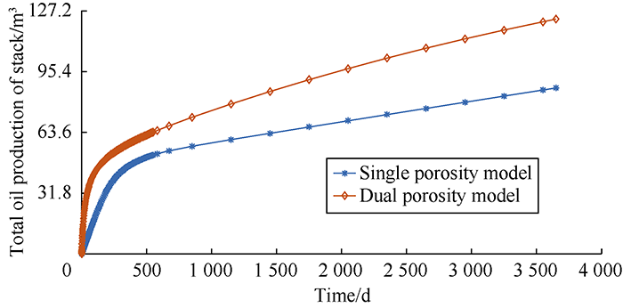
... A dual-porosity test plan was made exactly similar to the abovementioned model in the last section to find the differences between single-porosity and dual-porosity models. All of the needed properties for simulation such as rock and fluid properties, dimensions of matrix blocks, porosity, permeability, etc. were the same in both approaches. Fig. 4 shows the outcomes of the simulation for the test plans. The total oil drained from the stacked matrix blocks 10 years after production were simulated with the two models. The results show the single-porosity model can simulate the gravity drainage process in the naturally fractured reservoir precisely[31,52], while the dual-porosity approach overestimated the oil production rate. In the dual-porosity model not considering the reinfiltration effect, the drained oil from one matrix block entered into the fracture, and no oil entered the matrix block below. In contrast, in the single-porosity model, the oil drained from one matrix block may reinfiltrate into the other matrix blocks below. Ignoring the reinfiltration between matrix blocks is one of the main reasons for the inaccuracy in the simulation result of the dual-porosity model. This finding is in agreement with the results of other researchers[32,35]. ...
Simulation ofnaturally fractured reserviors. State of the art: Part 1-Physical mechanisms and simulator formulation
2
2010
... The reinfiltration would slow down the oil movement in the fractured reservoirs and cause a delay in production[22]. Festoy and Van Golf-Racht carried out a fine grid simulation and proved the presence of reinfiltration between two stacked matrix blocks[23]. In a theoretical study, Firoozabadi and Ishimoto found that the matrix block reinfiltration rate was always more than or equal to the drainage rate[24] and the reinfiltration rate across vertical faces of the matrix block varied significantly[25]. Moreover, a grid simulation was performed to find out the slope effect on the reinfiltration[26]. Firoozabadi et al. studied the impact of fracture aperture on the rate of oil drainage across stacked matrix blocks by experiments[27]. Sajjadian et al. sorted out the main parameters affecting the reinfiltration process[28]. Aghabarari et al. numerically simulated the reinfiltration process in 3 stacked matrix blocks to find the effect of different reservoir properties on reinfiltration[29]. After some experiments and numerical simulations, Mollaei et al. related the reinfiltration rate to the horizontal fracture width and the size of the matrix pore-throat[30]. More studies about the reinfiltration and capillary continuity can be found in the literature[31,32,33,34]. ...
... A dual-porosity test plan was made exactly similar to the abovementioned model in the last section to find the differences between single-porosity and dual-porosity models. All of the needed properties for simulation such as rock and fluid properties, dimensions of matrix blocks, porosity, permeability, etc. were the same in both approaches. Fig. 4 shows the outcomes of the simulation for the test plans. The total oil drained from the stacked matrix blocks 10 years after production were simulated with the two models. The results show the single-porosity model can simulate the gravity drainage process in the naturally fractured reservoir precisely[31,52], while the dual-porosity approach overestimated the oil production rate. In the dual-porosity model not considering the reinfiltration effect, the drained oil from one matrix block entered into the fracture, and no oil entered the matrix block below. In contrast, in the single-porosity model, the oil drained from one matrix block may reinfiltrate into the other matrix blocks below. Ignoring the reinfiltration between matrix blocks is one of the main reasons for the inaccuracy in the simulation result of the dual-porosity model. This finding is in agreement with the results of other researchers[32,35]. ...
Empirical modeling of gravity drainage in fractured porous media
1
2011
... The reinfiltration would slow down the oil movement in the fractured reservoirs and cause a delay in production[22]. Festoy and Van Golf-Racht carried out a fine grid simulation and proved the presence of reinfiltration between two stacked matrix blocks[23]. In a theoretical study, Firoozabadi and Ishimoto found that the matrix block reinfiltration rate was always more than or equal to the drainage rate[24] and the reinfiltration rate across vertical faces of the matrix block varied significantly[25]. Moreover, a grid simulation was performed to find out the slope effect on the reinfiltration[26]. Firoozabadi et al. studied the impact of fracture aperture on the rate of oil drainage across stacked matrix blocks by experiments[27]. Sajjadian et al. sorted out the main parameters affecting the reinfiltration process[28]. Aghabarari et al. numerically simulated the reinfiltration process in 3 stacked matrix blocks to find the effect of different reservoir properties on reinfiltration[29]. After some experiments and numerical simulations, Mollaei et al. related the reinfiltration rate to the horizontal fracture width and the size of the matrix pore-throat[30]. More studies about the reinfiltration and capillary continuity can be found in the literature[31,32,33,34]. ...
Block to block interactions and their effects on miscibility gravity drainage in fractured carbonate reservoirs, experimental and analytical results
1
2018
... The reinfiltration would slow down the oil movement in the fractured reservoirs and cause a delay in production[22]. Festoy and Van Golf-Racht carried out a fine grid simulation and proved the presence of reinfiltration between two stacked matrix blocks[23]. In a theoretical study, Firoozabadi and Ishimoto found that the matrix block reinfiltration rate was always more than or equal to the drainage rate[24] and the reinfiltration rate across vertical faces of the matrix block varied significantly[25]. Moreover, a grid simulation was performed to find out the slope effect on the reinfiltration[26]. Firoozabadi et al. studied the impact of fracture aperture on the rate of oil drainage across stacked matrix blocks by experiments[27]. Sajjadian et al. sorted out the main parameters affecting the reinfiltration process[28]. Aghabarari et al. numerically simulated the reinfiltration process in 3 stacked matrix blocks to find the effect of different reservoir properties on reinfiltration[29]. After some experiments and numerical simulations, Mollaei et al. related the reinfiltration rate to the horizontal fracture width and the size of the matrix pore-throat[30]. More studies about the reinfiltration and capillary continuity can be found in the literature[31,32,33,34]. ...
Fractured reservoir simulator capable of modeling block-block interaction
2
1989
... Por et al. developed a new simulator to consider the interaction between blocks by establishing an extra connection between the fractured medium and matrix blocks[35]. By constructing the drainage curves of three stacked blocks, Tan and Firoozabadi worked out a reservoir simulation method considering the interaction between blocks in fractured reservoir[36]. Donato et al. examined oil recovery by gravity drainage using the one-dimensional analytical and numerical analysis[37]. They also proposed the analytical equation for oil recovery as a function of time. Fung put forward a new method to handle the interaction between blocks in the field scale simulation of the naturally fractured reservoir, which involved the calculation of pseudo capillary potential[38]. De Guevara-Torres et al. modified the dual-porosity formula to include reinfiltration in the simulation of naturally fractured reservoir[39]. ...
... A dual-porosity test plan was made exactly similar to the abovementioned model in the last section to find the differences between single-porosity and dual-porosity models. All of the needed properties for simulation such as rock and fluid properties, dimensions of matrix blocks, porosity, permeability, etc. were the same in both approaches. Fig. 4 shows the outcomes of the simulation for the test plans. The total oil drained from the stacked matrix blocks 10 years after production were simulated with the two models. The results show the single-porosity model can simulate the gravity drainage process in the naturally fractured reservoir precisely[31,52], while the dual-porosity approach overestimated the oil production rate. In the dual-porosity model not considering the reinfiltration effect, the drained oil from one matrix block entered into the fracture, and no oil entered the matrix block below. In contrast, in the single-porosity model, the oil drained from one matrix block may reinfiltrate into the other matrix blocks below. Ignoring the reinfiltration between matrix blocks is one of the main reasons for the inaccuracy in the simulation result of the dual-porosity model. This finding is in agreement with the results of other researchers[32,35]. ...
Dual-porosity simulation incorporating reinfiltration and capillary continuity concepts part I: Single gridcell
1
1995
... Por et al. developed a new simulator to consider the interaction between blocks by establishing an extra connection between the fractured medium and matrix blocks[35]. By constructing the drainage curves of three stacked blocks, Tan and Firoozabadi worked out a reservoir simulation method considering the interaction between blocks in fractured reservoir[36]. Donato et al. examined oil recovery by gravity drainage using the one-dimensional analytical and numerical analysis[37]. They also proposed the analytical equation for oil recovery as a function of time. Fung put forward a new method to handle the interaction between blocks in the field scale simulation of the naturally fractured reservoir, which involved the calculation of pseudo capillary potential[38]. De Guevara-Torres et al. modified the dual-porosity formula to include reinfiltration in the simulation of naturally fractured reservoir[39]. ...
Analytical and numerical analysis of oil recovery by gravity drainage
1
2006
... Por et al. developed a new simulator to consider the interaction between blocks by establishing an extra connection between the fractured medium and matrix blocks[35]. By constructing the drainage curves of three stacked blocks, Tan and Firoozabadi worked out a reservoir simulation method considering the interaction between blocks in fractured reservoir[36]. Donato et al. examined oil recovery by gravity drainage using the one-dimensional analytical and numerical analysis[37]. They also proposed the analytical equation for oil recovery as a function of time. Fung put forward a new method to handle the interaction between blocks in the field scale simulation of the naturally fractured reservoir, which involved the calculation of pseudo capillary potential[38]. De Guevara-Torres et al. modified the dual-porosity formula to include reinfiltration in the simulation of naturally fractured reservoir[39]. ...
Simulation of block-to-block processes in naturally fractured reservoirs
1
1991
... Por et al. developed a new simulator to consider the interaction between blocks by establishing an extra connection between the fractured medium and matrix blocks[35]. By constructing the drainage curves of three stacked blocks, Tan and Firoozabadi worked out a reservoir simulation method considering the interaction between blocks in fractured reservoir[36]. Donato et al. examined oil recovery by gravity drainage using the one-dimensional analytical and numerical analysis[37]. They also proposed the analytical equation for oil recovery as a function of time. Fung put forward a new method to handle the interaction between blocks in the field scale simulation of the naturally fractured reservoir, which involved the calculation of pseudo capillary potential[38]. De Guevara-Torres et al. modified the dual-porosity formula to include reinfiltration in the simulation of naturally fractured reservoir[39]. ...
Gravity-drainage and oil-reinfiltration modeling in naturally fractured reservoir simulation
1
2009
... Por et al. developed a new simulator to consider the interaction between blocks by establishing an extra connection between the fractured medium and matrix blocks[35]. By constructing the drainage curves of three stacked blocks, Tan and Firoozabadi worked out a reservoir simulation method considering the interaction between blocks in fractured reservoir[36]. Donato et al. examined oil recovery by gravity drainage using the one-dimensional analytical and numerical analysis[37]. They also proposed the analytical equation for oil recovery as a function of time. Fung put forward a new method to handle the interaction between blocks in the field scale simulation of the naturally fractured reservoir, which involved the calculation of pseudo capillary potential[38]. De Guevara-Torres et al. modified the dual-porosity formula to include reinfiltration in the simulation of naturally fractured reservoir[39]. ...
An analytical scaling method for spontaneous imbibition in gas/water/rock systems
1
2004
... The scaling equation is an effective method to predict the production of naturally fractured reservoirs. Scaling equations were built for the imbibition process before[40,41,42,43,44,45,46,47,48,49,50]. But to the best of our knowledge, the scaling equation has not been used to study the reinfiltration phenomenon yet. ...
Generalized scaling of spontaneous imbibition data for strongly water-wet systems
1
1997
... The scaling equation is an effective method to predict the production of naturally fractured reservoirs. Scaling equations were built for the imbibition process before[40,41,42,43,44,45,46,47,48,49,50]. But to the best of our knowledge, the scaling equation has not been used to study the reinfiltration phenomenon yet. ...
Universal scaling of spontaneous imbibition for water-wet systems
1
2012
... The scaling equation is an effective method to predict the production of naturally fractured reservoirs. Scaling equations were built for the imbibition process before[40,41,42,43,44,45,46,47,48,49,50]. But to the best of our knowledge, the scaling equation has not been used to study the reinfiltration phenomenon yet. ...
Correlation for the effect of fluid viscosities on counter-current spontaneous imbibition
1
2010
... The scaling equation is an effective method to predict the production of naturally fractured reservoirs. Scaling equations were built for the imbibition process before[40,41,42,43,44,45,46,47,48,49,50]. But to the best of our knowledge, the scaling equation has not been used to study the reinfiltration phenomenon yet. ...
Oil production by spontaneous imbibition from sandstone and chalk cylindrical cores with two ends open
1
2010
... The scaling equation is an effective method to predict the production of naturally fractured reservoirs. Scaling equations were built for the imbibition process before[40,41,42,43,44,45,46,47,48,49,50]. But to the best of our knowledge, the scaling equation has not been used to study the reinfiltration phenomenon yet. ...
Scaling of counter-current imbibition processes in low-permeability porous media
1
2002
... The scaling equation is an effective method to predict the production of naturally fractured reservoirs. Scaling equations were built for the imbibition process before[40,41,42,43,44,45,46,47,48,49,50]. But to the best of our knowledge, the scaling equation has not been used to study the reinfiltration phenomenon yet. ...
Oil recovery by spontaneous imbibition from weakly water-wet rocks
1
2001
... The scaling equation is an effective method to predict the production of naturally fractured reservoirs. Scaling equations were built for the imbibition process before[40,41,42,43,44,45,46,47,48,49,50]. But to the best of our knowledge, the scaling equation has not been used to study the reinfiltration phenomenon yet. ...
Generalized scaling approach for spontaneous imbibition: An analytical model
1
2006
... The scaling equation is an effective method to predict the production of naturally fractured reservoirs. Scaling equations were built for the imbibition process before[40,41,42,43,44,45,46,47,48,49,50]. But to the best of our knowledge, the scaling equation has not been used to study the reinfiltration phenomenon yet. ...
Discussion on similarity of recovery curves in scaling of imbibition process in fractured porous media
1
2016
... The scaling equation is an effective method to predict the production of naturally fractured reservoirs. Scaling equations were built for the imbibition process before[40,41,42,43,44,45,46,47,48,49,50]. But to the best of our knowledge, the scaling equation has not been used to study the reinfiltration phenomenon yet. ...
Modified shape factor incorporating gravity effects for scaling countercurrent imbibition
1
2017
... The scaling equation is an effective method to predict the production of naturally fractured reservoirs. Scaling equations were built for the imbibition process before[40,41,42,43,44,45,46,47,48,49,50]. But to the best of our knowledge, the scaling equation has not been used to study the reinfiltration phenomenon yet. ...
Scaling one- and multi-dimensional co-current spontaneous imbibition processes in fractured reservoirs
1
2017
... The scaling equation is an effective method to predict the production of naturally fractured reservoirs. Scaling equations were built for the imbibition process before[40,41,42,43,44,45,46,47,48,49,50]. But to the best of our knowledge, the scaling equation has not been used to study the reinfiltration phenomenon yet. ...
ECLIPSE 100 reference manual
1
2010
... The numerical simulator (black-oil simulator ECLIPSE100[51]) was used to study the gravity drainage process affected by reinfiltration, and the effects of different parameters such as rock and fluid properties, dimensions of matrix blocks, porosity, permeability, etc. on reinfiltration. ...
Matrix-fracture transfer function in dual-medium flow simulation: Review, comparison, and validation
2
2008
... Single-porosity approach is an effective method to evaluate the production mechanisms in naturally fractured reservoirs. In this method, fractures and matrix blocks are defined explicitly by fine grids[52,53]. It should be mentioned that although the single-porosity approach can predict and describe production mechanisms accurately, it takes long computation time, so this approach isn’t practical for large scale field simulation. The single-porosity approach was used to build a model of fractured reservoir in this work, as this approach enables us to have an accurate and detailed description of the fluid flow in the fractured reservoir (including gravity drainage and reinfiltration). ...
... A dual-porosity test plan was made exactly similar to the abovementioned model in the last section to find the differences between single-porosity and dual-porosity models. All of the needed properties for simulation such as rock and fluid properties, dimensions of matrix blocks, porosity, permeability, etc. were the same in both approaches. Fig. 4 shows the outcomes of the simulation for the test plans. The total oil drained from the stacked matrix blocks 10 years after production were simulated with the two models. The results show the single-porosity model can simulate the gravity drainage process in the naturally fractured reservoir precisely[31,52], while the dual-porosity approach overestimated the oil production rate. In the dual-porosity model not considering the reinfiltration effect, the drained oil from one matrix block entered into the fracture, and no oil entered the matrix block below. In contrast, in the single-porosity model, the oil drained from one matrix block may reinfiltrate into the other matrix blocks below. Ignoring the reinfiltration between matrix blocks is one of the main reasons for the inaccuracy in the simulation result of the dual-porosity model. This finding is in agreement with the results of other researchers[32,35]. ...
Realistic numerical models for fractured reservoirs
1
2000
... Single-porosity approach is an effective method to evaluate the production mechanisms in naturally fractured reservoirs. In this method, fractures and matrix blocks are defined explicitly by fine grids[52,53]. It should be mentioned that although the single-porosity approach can predict and describe production mechanisms accurately, it takes long computation time, so this approach isn’t practical for large scale field simulation. The single-porosity approach was used to build a model of fractured reservoir in this work, as this approach enables us to have an accurate and detailed description of the fluid flow in the fractured reservoir (including gravity drainage and reinfiltration). ...
Application of the recovery curve method for evaluation of matrix-fracture interactions
1
2015
... The most common approach for field-scale simulation of a naturally fractured reservoir is the dual-porosity model[54]. The dual-porosity model was first introduced to the petroleum industry by Warren and Root[55]. It is lower in computational cost than the single-porosity method. In the dual-porosity approach, the oil flow between the fracture and matrix block is defined by a matrix-fracture transfer function. As the effect of oil reinfiltration from fracture to the matrix block is not completely considered in the dual-porosity approach[31], in this work, we tried to make use of the single-porosity approach to find out a way for estimating the reinfiltration rate or drainage rate of a matrix block under the effect of reinfiltration. The result of this work can improve the accuracy of the dual-porosity approach too. ...
The behavior of naturally fractured reservoirs
1
1963
... The most common approach for field-scale simulation of a naturally fractured reservoir is the dual-porosity model[54]. The dual-porosity model was first introduced to the petroleum industry by Warren and Root[55]. It is lower in computational cost than the single-porosity method. In the dual-porosity approach, the oil flow between the fracture and matrix block is defined by a matrix-fracture transfer function. As the effect of oil reinfiltration from fracture to the matrix block is not completely considered in the dual-porosity approach[31], in this work, we tried to make use of the single-porosity approach to find out a way for estimating the reinfiltration rate or drainage rate of a matrix block under the effect of reinfiltration. The result of this work can improve the accuracy of the dual-porosity approach too. ...
Inspectional and dimensional analyses for scaling of low salinity waterflooding (LSWF): From core to field scale
1
2020
... The inspectional analysis was used to find a new scaling equation[56,57,58,59,60]. First, one needs to determine the governing equation of flow for the reinfiltration mechanism, in which all parameters affecting the fractured reservoir such as permeability-porosity, matrix block cross-sectional area, rock type, fluid type, and matrix block height[29], as well as the effect of capillary pressure, gravity, and viscous forces must be taken into account. Thus, the one-dimensional flow equation in multiple phase flow for oil which is the fundamental equation in reservoir simulation[61] was used in this study: ...
Scaling equations for oil/gas recovery from fractured porous media by counter-current spontaneous imbibition: From development to application
1
2013
... The inspectional analysis was used to find a new scaling equation[56,57,58,59,60]. First, one needs to determine the governing equation of flow for the reinfiltration mechanism, in which all parameters affecting the fractured reservoir such as permeability-porosity, matrix block cross-sectional area, rock type, fluid type, and matrix block height[29], as well as the effect of capillary pressure, gravity, and viscous forces must be taken into account. Thus, the one-dimensional flow equation in multiple phase flow for oil which is the fundamental equation in reservoir simulation[61] was used in this study: ...
Analysis of counter-current spontaneous imbibition in presence of resistive gravity forces: Displacement characteristics and scaling
1
2015
... The inspectional analysis was used to find a new scaling equation[56,57,58,59,60]. First, one needs to determine the governing equation of flow for the reinfiltration mechanism, in which all parameters affecting the fractured reservoir such as permeability-porosity, matrix block cross-sectional area, rock type, fluid type, and matrix block height[29], as well as the effect of capillary pressure, gravity, and viscous forces must be taken into account. Thus, the one-dimensional flow equation in multiple phase flow for oil which is the fundamental equation in reservoir simulation[61] was used in this study: ...
Scaling equation for counter current imbibition in the presence of gravity forces considering initial water saturation and SCAL properties
1
2016
... The inspectional analysis was used to find a new scaling equation[56,57,58,59,60]. First, one needs to determine the governing equation of flow for the reinfiltration mechanism, in which all parameters affecting the fractured reservoir such as permeability-porosity, matrix block cross-sectional area, rock type, fluid type, and matrix block height[29], as well as the effect of capillary pressure, gravity, and viscous forces must be taken into account. Thus, the one-dimensional flow equation in multiple phase flow for oil which is the fundamental equation in reservoir simulation[61] was used in this study: ...
Scaling laws for use in design and operation of water-oil flow models
1
1955
... The inspectional analysis was used to find a new scaling equation[56,57,58,59,60]. First, one needs to determine the governing equation of flow for the reinfiltration mechanism, in which all parameters affecting the fractured reservoir such as permeability-porosity, matrix block cross-sectional area, rock type, fluid type, and matrix block height[29], as well as the effect of capillary pressure, gravity, and viscous forces must be taken into account. Thus, the one-dimensional flow equation in multiple phase flow for oil which is the fundamental equation in reservoir simulation[61] was used in this study: ...
Basic applied reservoir simulation
1
2001
... The inspectional analysis was used to find a new scaling equation[56,57,58,59,60]. First, one needs to determine the governing equation of flow for the reinfiltration mechanism, in which all parameters affecting the fractured reservoir such as permeability-porosity, matrix block cross-sectional area, rock type, fluid type, and matrix block height[29], as well as the effect of capillary pressure, gravity, and viscous forces must be taken into account. Thus, the one-dimensional flow equation in multiple phase flow for oil which is the fundamental equation in reservoir simulation[61] was used in this study: ...
Characterization of spontaneous water imbibition into gas-saturated rocks
0
2001
The interrelation between gas and oil relative permeabilites
1
1954
... Through a numerical simulation, Aghabarari et al. sorted out the parameters affecting reinfiltration. Theses parameters in descending order of importance are permeability, porosity, matrix block cross-sectional area, rock type, fluid type, and matrix block height[29]. To check the applicability of the introduced dimensionless equation (Equation 12), various cases were defined, and the ranges of the parameters were defined to characterize different types of naturally fractured reservoirs. By use of Corey correlation of oil and gas[63], three types of rocks (i.e. Types I, II, and III) were defined. These rock types have different connate water saturations, capillary pressures, and relative permeability curves according to Fig. 5 and Fig. 6. Rock type I has the lowest oil wettability while rock type III is highly oil-wet. The characteristics of fluids in the three types of reservoirs are shown in Table 1. Here oils are defined as type I to III in ascending order of density. ...
Scaling of spontaneous imbibition in gas- liquid- rock systems
1
2002
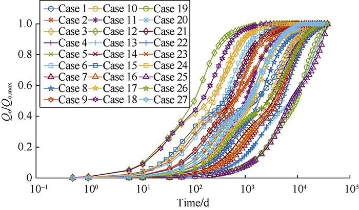
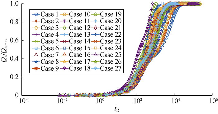
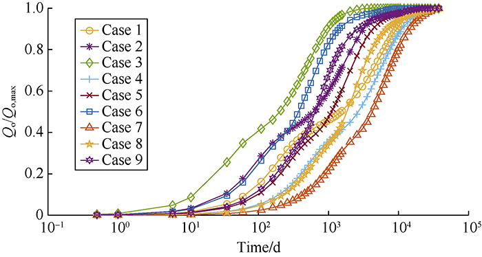
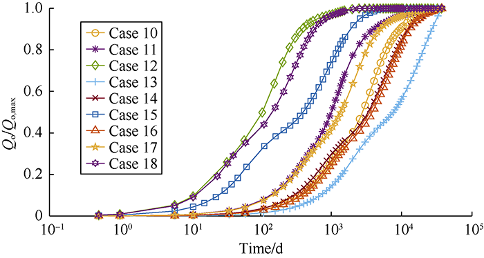
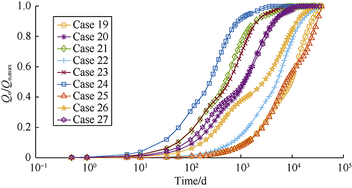
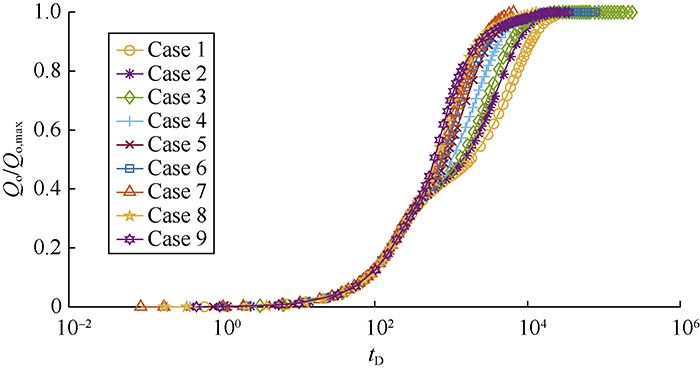
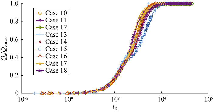
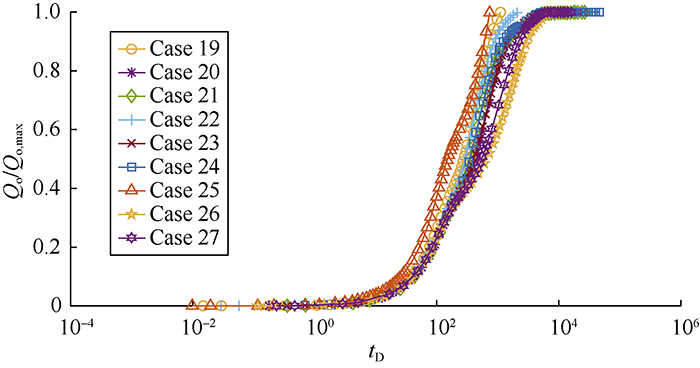
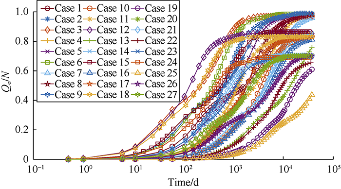
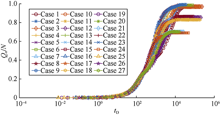
... According to Li and Horne, there are various ways to establish a scaling equation for recovery[64]. In one definition, recovery can be expressed in terms of recoverable reserves (Figs. 8-14, Qo/Qo,max), while in another one, it is represented in terms of initial oil in place (Figs. 15-16, Qo/N). Fig. 7 shows the recoveries of the defined cases in Table 2 based on the ultimate recovery of each test. Fig. 8 shows the variation of recovery with dimensionless time calculated by using Equation 12 for the test cases in Fig. 7. The changes of slopes in the middle sections of curves in Fig. 7 are caused by the reinfiltration effect on the second matrix block. When the oil drainage rate of the second matrix block decreases, the reinfiltration of the oil drained out from the above matrix block makes the oil drainage rate of this block rise again. The saturation related parameters in Equation 12, particularly $\partial {p_c}/ \partial {S_o}$ and Kro vary widely with time, and will lower the scaling equation performance. It is confirmed through this study that the scaling equation reaches the best effect when pc and Kro reach the maximum values. In addition, separating the test cases into 3 groups according to the rock types can eliminate the dependency of the scaling equation on the parameters mentioned above and get a better scaling effect. The curves of oil recovery with time after groups according to the rock types are shown in Figs. 9-11. Figs. 12-14 show the recovery curves calculated by using Equation 12 for the 3 groups of cases according to rock types. ...


