Introduction
Fractured oil reservoirs with huge oil reserves play an important role in ensuring the security of the energy strategy of China[1]. In the development process of fractured oil reservoirs, the oil in the matrix is difficult to be mobilized due to the different flow features between fractures and matrix. The key to enhancing oil recovery (EOR) of fractured reservoirs is to realize the oil-water replacement between fractures and matrix[2]. Under this background, for the purpose of screening high efficient replacement fluid, researchers in China and abroad have carried out experimental studies on many fluids with the performances of wettability alteration, oil solubilization, viscosity reducing and low interfacial tension, including low salinity water[3], surfactant solutions[4], nanofluids[5,6], and in-situ microemulsion[7,8]. The imbibition test is a common and direct experimental method to simulate the water-oil replacement dynamics between fractures and the matrix [9,10,11]. But the present imbibition experiments, mainly on core samples, have three main problems[12]: (1) the produced oil is usually attached on the surface of the core, and the recovery degree measurement is inaccurate; (2) the experimental period is long; (3) only the dynamic production curve of imbibition is obtained from the experiment[13]. It is an urgent to explore experimental methods that can visualize the dynamics of oil-water displacement between the matrix and fractures, to facilitate in-depth study on the imbibition mechanisms.
To clarify the displacing mechanism of oil during the imbibition process, the core imbibition tests coupled with NMR and Micro CT scanning have been widely used. The oil recovery of pores with different sizes can be quantified by the NMR test[14,15,16,17]. And the oil occurrence state in pores during the imbibition process can be reconstructed through the Micro CT test. But these two methods can not explain the action mechanism between oil and chemicals on the interface. Meanwhile, the microfluidic chip model is an effective tool for studying the interaction between chemicals and oil, which can directly visualize the multiphase flow dynamics in porous media[18]. In recent years, many researchers have designed and manufactured 3D glass microfluidic models similar to the realistic formations to study the wettability alteration, diffusion, emulsification and imbibition to reveal working mechanisms of chemicals and screen chemicals for EOR[7-8, 19-20]. However, most imbibition tests with microfluidic models are conducted on 2D micromodel with the identical depth of fractures and matrix, which can’t simulate the underground imbibition environment between fractures and matrix accurately.
A series microfluidic models with different sizes, wettability, and boundary conditions were designed, which provided a quick method for imbibition tests and also could visualize and analyze quantitatively the oil-water replacement between fractures and matrix. By using these microfluidic models, the imbibition tests between oil-water, oil-wettability alteration fluids, and oil-Winsor III type surfactant solution were conducted to reveal the imbibition mechanisms between fracture and matrix.
1. Design and manufacture of the microfluidic models
1.1. Microfluidic model design
The pore structure was extracted from the Micro CT scan image through the image processing method and then processed by binary method. The basic pore structure network was connected through the watershed algorithm by adding throats[21]. According to the study objectives of the imbibition experiments and field view of microscope, a series of fracture network models of different sizes and boundary conditions were designed (Fig. 1). Meanwhile, the microfluidic models were designed by splicing the basic pore units (grids in black dash lines). The basic pore unit was 1.2 mm×1.2 mm each.
Fig. 1.
Fig. 1.
The design of fracture network. AFO—All faces open; TEO—Two ends open; OEO—One end open.
1.2. Microfluidic model manufacture
The fracture-matrix microfluidic models were made by two-step etching method: (1) the fractures were etched on the glass through the fracture network mask; (2) the matrix was etched on the glass with etched fractures through the matrix mask. The alignment of the fracture channels and matrix channels was realized by cross- cursor method[8]. The fractures in the model were much larger in width and depth than throats in the matrix by controlling the etching time. Hence, the models can reflect the actual permeability differences between fractures and matrix in formation and avoid the effect of waterflooding in fracture to matrix in the experiments.
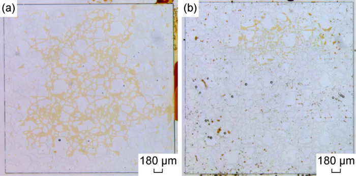
As shown in Fig. 2, the color of oil in fractures is deeper than that in matrix after saturation, proving the difference in the depths of the fracture and matrix. The fractures in all the models were same in width (400 μm) and depth (30 μm); the pores in the matrix were 10 μm wide and 3 μm deep on average. The model could be changed from water wettability to oil wettability by soaking with ethanol solution (with trimethyl chlorosilane mass fraction of 1%)[7,8].
Fig. 2.
Fig. 2.
Images of models saturated with oil.
2. Design of imbibition tests
2.1. Equipment and materials
The experimental equipment mainly includes a Leica M165FC Fluorescence stereo microscope, a Leica DFC450 Camera (100 frames per second, 2560 pixels×1920 pixels), a Fuigent MFCS-EZ pump, and Harvard pump, etc.
The oil used in the experiments was crude oil with a viscosity of 9.1 mPa·s at 20 °C, the surfactants used in the experiments were the ENORDE O332 of Shell company and the PETROSETP S-13B of the Stepan company, and the cosolvent was the N-butanol of the Aladdin company.
The chemicals used in this study were chosen according to test results of the prophase study[21]. The wettability alteration solution was composed of 0.75% surfactant S-13B, 0.25% surfactant O332, 2% cosolvent and 3% KCl solution. The Winsor III type surfactant solution was composed of 0.75% surfactant S-13B, 0.25% surfactant O332, 2% cosolvent and 5.25% KCl solution.
The interfacial tension (IFT) of the wettability alteration solution and oil was 1.1 mN/m measured by the Texas-500 interfacial tension meter. The IFT of the Winsor III type surfactant solution and oil was 3×10⁻³ mN/m calculated by the Huh theory[22]. The Winsor III type surfactant with stronger oil solubility can form microemulsion with the crude oil.
2.2. Experimental scheme and steps
Twenty one groups of imbibition experiments were designed in this study as shown in Table 1. The experimental steps are as follows:
Table 1 Design of the experimental scheme.
| No. | Fluid | Side length of model/mm | Boundary condition | Wettability | Place state | Research factor |
|---|---|---|---|---|---|---|
| A-1 | Water | 1.2 | AFO | Water-wet | Vertically | Wettability |
| A-2 | 1.2 | AFO | Oil-wet | Vertically | ||
| A-3 | 3.6 | AFO | Water-wet | Horizontally | Gravity | |
| A-4 | 3.6 | AFO | Water-wet | Vertically | ||
| A-5 | 8.4 | AFO | Water-wet | Vertically | Size | |
| A-6 | 1.2 | TEO | Water-wet | Vertically | Boundary condition | |
| A-7 | 1.2 | OEO | Water-wet | Vertically | ||
| B-1 | Wettability alteration solution | 1.2 | AFO | Oil-wet | Vertically | Wettability |
| B-2 | 1.2 | AFO | Water-wet | Vertically | ||
| B-3 | 3.6 | AFO | Oil-wet | Horizontally | Gravity | |
| B-4 | 3.6 | AFO | Oil-wet | Vertically | ||
| B-5 | 8.4 | AFO | Oil-wet | Vertically | Size | |
| B-6 | 1.2 | TEO | Oil-wet | Vertically | Boundary condition | |
| B-7 | 1.2 | OEO | Oil-wet | Vertically | ||
| C-1 | Winsor III Type surfactant solution | 1.2 | AFO | Oil-wet | Vertically | Wettability |
| C-2 | 1.2 | AFO | Water-wet | Vertically | ||
| C-3 | 3.6 | AFO | Oil-wet | Horizontally | Gravity | |
| C-4 | 3.6 | AFO | Oil-wet | Vertically | ||
| C-5 | 8.4 | AFO | Oil-wet | Vertically | Size | |
| C-6 | 1.2 | TEO | Oil-wet | Vertically | Boundary condition | |
| C-7 | 1.2 | OEO | Oil-wet | Vertically |
Note: All models were water-wet before the surface modification by ethanol solution (with trimethyl chlorosilane mass fraction of 1%).
(1) Saturated with oil: The crude oil was injected into the model under the constant pressure of 0.1 MPa, when oil flew out of the outlet, the injection pressure was increased to 0.3 MPa to degas, then the oil saturated models were soaked in the crude oil for 24 h. (2) Oil-water imbibition: The water was injected into the model at a constant rate of 0.1 μL/min, and the injection was stopped after 10 PV (pore volumes) of waterflooding, then the model was soaked in the water for oil-water imbibition, and the images and videos were collected at regular intervals. (3) Oil-chemical imbibition: After the oil-water imbibition, the wettability alteration system or Winsor III surfactant system was injected into the model at a constant rate of 0.1 μL/min, and the injection was stopped after 10 PV of displacing, then the model was soaked in the wettability alteration fluid or Winsor III surfactant system and the images and videos were collected at regular intervals.
3. Imbibition experiment
3.1. Imbibition mechanisms between fracture and matrix
3.1.1. Oil-water
The imbibition of water and oil in the water-wet model shows water is absorbed into the matrix, and the oil flows from matrix to fractures in this process (e.g. Scheme A-1 and Fig. 3). It can be seen the oil-water imbibition in water-wet porous media is a countercurrent imbibition process, the oil phase is produced in oil droplets and increases at the edge of the model over time, which is consistent with previous studies[12].
Fig. 3.
Fig. 3.
Water-oil imbibition dynamics in water-wet model (Scheme A-1).
As shown in Fig. 4, the process of oil (yellow part) production is a cyclic process: the front edge of the oil enters the fractures from the matrix as convex liquid level (Fig. 4a-4d), then the oil as non-wetting phase on the interface between matrix and fractures is squeezed and snapped off by the wetting phase (water, blue part) in the fractures (Fig. 4e), finally the oil enters in the fractures in droplets (Fig. 4f, 4g). This is a typical process of Haines jump, which is driven by pressure difference between oil and water (i.e. capillary pressure) that is expressed as the Eq. (1)[23]:
Fig. 4.
Fig. 4.
Microscopic images of oil producing process in Scheme A-1.
After oil-water imbibition, the occurrence state of the residual oil in the matrix of water-wet model is shown in Fig. 5. The water phase is the continuous wetting phase in the strongly water-wet porous media, which occupies the edges of the pores; while the oil phase is the non-wetting phase, which mainly occupies the central part of the pores and has little contact with the rock. At this point, losing the drive of the capillary pressure and affected by its own size, the oil can’t move further under the effect of buoyancy, and is retained in the pore to become residual oil.
Fig. 5.
Fig. 5.
The occurrence state of residual oil after imbibition in Scheme A-1.
3.1.2. Oil-wettability alteration solution
After injecting wettability alteration solution, the con-tact relation of oil, water and rock in the micromodel obviously changed as shown in Fig. 6, and the micromodel changed from oil wettability to water wettability. This laid a foundation for the following experiments.
Fig. 6.
Fig. 6.
The effect of wettability alteration solution on oil in the fracture channels.
Under the effect of the wettability alteration solution, the oil production from the oil-wet model is shown in Fig. 7. The oil droplets become larger and get closer to the rock compared with oil-water imbibition in Scheme A-1.
Fig. 7.
Fig. 7.
The produced oil images under the effect of the wettability alteration solution systems in Scheme B-6 (a) and B-2 (b).
Under the effect of the wettability alteration solution, the oil-wet micromodel presented water-wet characteristics. The oil was displaced by the capillary pressure which can also be characterized by the Eq. (1). However, under the effect of low IFT, the capillary pressure and capillary back pressure weakened, the oil producing rate became slower and oil droplets were not easy to snap off and observed in larger shape, as shown in Fig. 8.
Fig. 8.
Fig. 8.
The microscopic images of oil expulsion under the effect of wettability alteration solution in Scheme B-1.
It can be seen from Fig. 9 that smaller oil droplets formed in the porous media flew directly from matrix into the fracture, which is the result of the emulsification effect of the wettability alteration solution compared with oil-water imbibition in water-wet model during Haynes step. Under the low IFT condition, the oil phase is more likely to be cut into emulsion during migration. When the oil-in-water emulsion droplets are small enough (smaller than the flow channel), they can flow directly into the fractures under the effect of buoyancy.
Fig. 9.
Fig. 9.
Microscopic image in the late stage of imbibition of Scheme B-1 under the effect of wettability alteration solution.
After the oil and wettability alteration solution imbibition, residual oil inside the matrix occurs in three kinds of states (Fig. 10): (1) large oil droplets formed by shearing effect trapped in pores; (2) oil not fully peeling off from the rock wall surface due to adhesion in the pores, although the rock is water-wet under the effect of wettability alteration solution; (3) continuous residual oil in some pores which are still oil-wet. The wettability alteration solution mainly makes the interface of oil-water move by changing the separation pressure at the interface of oil-water-rock to realize the reversal of wettability. But in the sites where oil film covers the whole rock surface, the effect of the wettability alteration solution is poor, so the rock is still oil-wet, and the residual oil still occupies the whole pores.
Fig. 10.
Fig. 10.
Occurrence states of residual oil after the oil and wettability alteration solution imbibition in scheme B-1. ① Large oil droplets formed by the shearing effect, which are trapped in the pores due to the restriction of throats; ② Oil not completely peeling off from the wall surface in the pores due to adhesion; ③ Continuous oil occupying the whole pores.
3.1.3. Oil-Winsor III type surfactant solution
The effect of Winsor III type surfactant solution on oil in the oil-wet model is shown in Fig. 11. The model was still oil-wet just after the injection of the Winsor III type surfactant solution, but the diffusion belt of middle phase microemulsion and surfactant was observed at the interface between the surfactant solution and oil (Fig. 11a), and the diffusion of surfactant will promote the formation of more microemulsion. In the original oil-wet model, compared with the oil phase and Winsor III surfactant solution, the middle phase microemulsion is the wetting phase (Fig. 11 b, 11 c). Different from the wettability alteration solution that changes the wettability of oil-wet model directly, the Winsor III surfactant solution realize wettability reversal by forming microemulsion with higher wettability[7]. After soaking for some time, the middle phase microemulsion was diluted and turned lighter in color, many surfactant droplets were observed, and the interface between the microemulsion and Winsor III surfactant solution became fuzzy, this is caused by the dynamic equilibrium of microemulsion[21]. Affected by local equilibrium conditions, the middle phase microemulsion first formed around oil phase, then interacted with excessive Winsor III surfactant to transit to bottom phase microemulsion. As the oil dissolved by Winsor III surfactant was much higher than the residual oil in the model, after reaching equilibrium, the fluid filling the model was bottom phase microemulsion.
Fig. 11.
Fig. 11.
Dynamics of the interaction between Winsor III type surfactant solution and oil in oil-wet model.
It can be seen from Fig. 12 that the imbibition process of Winsor III type surfactant is a forward current imbibition process, in which the Winsor III type surfactant is imbibed from the bottom of the model to form middle phase microemulsion with oil, and the oil phase is produced from the top of the model under the effect of buoyancy.
Fig. 12.
Fig. 12.
Microscopic images of imbibition under the effect of Winsor III type surfactant solution in Scheme C-4.
Fig. 13 shows the oil production dynamics under the effect of the Winsor III type surfactant solution. It can be seen that the oil phase discharges from the matrix from the model top in the form of middle phase microemulsion continuously. According to the equilibrium theory of microemulsion, the middle phase microemulsion would be diluted and reach equilibrium again into the bottom phase microemulsion. This is consistent with the produced fluid observed in the core imbibition experiment[13]. Due to the ultra-low IFT between the microemulsion, oil and Winsor III surfactant, the Haines jump didn't occur, the produced middle phase microemulsion would spread on the rock surface and finally enter the fracture from matrix under the effect of buoyancy or solubilization.
Fig. 13.
Fig. 13.
Oil production process under the effect of Winsor III type surfactant solution in Scheme C-4. ①Microemulsion; ② Oil in the fracture; ③ Oil in matrix pores.
Based on above descriptions, three mechanisms could be summarized for the Winsor III type surfactant solution and oil imbibition: buoyancy effect under the ultra-low IFT, oil solubilization during the formation and re-equilibrium of the middle phase microemulsion, and the spread effect of the middle phase microemulsion.
3.2. Main factors affecting imbibition
3.2.1. Wettability
For the capillary pressure dominated imbibition, the wettability is the factor controlling the start of the imbibition. Compared to the results of Scheme A-1 (Fig. 5), the capillary pressure is the resistance for water entering the matrix, and the water in the fracture still couldn’t enter the oil-wet matrix after 40 h of imbibition (Fig. 14). This result also verified the oil-wet nature of the microfluidic model after wettability alteration by ethanol solution with 1% trimethyl chlorosilane.
Fig. 14.
Fig. 14.
Experimental result of Scheme A-2 after 40 h of imbibition.
The wettability alteration solution can change the wettability of the oil-wet porous media, thus make the capillary pressure in the oil-wet matrix the driving force of imbibition, and make water replace oil in the matrix. The oil-wet model in Scheme B-1 had the imbibition recovery close to that of the water-wet model in A-1 (Fig. 15). But the wettability alteration solution has little effect on the residual oil in the water-wet media after oil-water imbibition (Fig. 16). In this case, with little flow field disturbance, the wettability alteration solution has little emulsification effect on the residual oil after imbibition, and the residual oil was hardly produced.
Fig. 15.
Fig. 15.
Experimental results of oil-water imbibition (a) and oil-wettability alteration solution imbibition (b) in Scheme B-1.
Fig. 16.
Fig. 16.
Experimental results of oil-water imbibition (a) and oil-wettability alteration solution imbibition (b) in Scheme B-2.
Different from the above results, for the imbibition of Winsor III type surfactant solution with super low IFT, the capillary pressure isn’t the main driving force of imbibition, wettability has little effect on the start of imbibition, and the residual oil in both water-wet matrix and oil-wet matrix was mobilized by buoyancy and solubilization effect of the Winsor III type surfactant solution (Fig. 17).
Fig. 17.
Fig. 17.
Scheme C-2 (a) and Scheme C-1 (b) images before and after imbibition test.
3.2.2. Gravity
Fig. 18 shows the imbibition results of Scheme A-3 and Scheme A-4. It can be seen that, the model placed horizontally and the model placed vertically had similar recoveries, which suggests that buoyancy has little effect on the oil-water imbibition in water-wet porous media, and this process is mainly controlled by capillary pressure.
Fig. 18.
Fig. 18.
The imbibition results of Scheme A-3 (a) and Scheme A-4 (b).
Fig. 19 shows the experimental results of Scheme B-3 and Scheme B-4. It can be seen that the vertically placed micromodel has imbibition recovery higher than the horizontally placed micromodel. From the above analysis, due to the emulsification effect, oil droplets in the micromodel can be produced by buoyancy, but this effect only works when the microemulsion droplets are smaller than the throat in size. Thus, in the experimental condition of these schemes, gravity contributes to some degree to the recovery enhancement in the imbibition process of the wettability alteration solution, and the imbibition of wettability alteration solution is still dominated the capillary pressure.
Fig. 19.
Fig. 19.
Imbibition results of Scheme B-3 (a) and Scheme B-4 (b).
Fig. 20 shows the experimental results of Scheme C-3 and Scheme C-4. It can be seen that the vertically placed micromodel has much higher imbibition recovery than that of the horizontally placed micromodel. This implies the gravity dominates the imbibition process of Winsor III type surfactant solution. Although the oil diffusion and solution effect of the Winsor III type surfactant also makes contribution to the ultimate imbibition recovery, according to the prophase study of Yu et al.[21], the dilution of the formed middle phase microemulsion by the surfactant is very slow, and would hinder the interaction between the surfactant and oil in the model, so the diffusion of the surfactant has limited contribution to recovery of oil in matrix.
Fig. 20.
Fig. 20.
Imbibition results of Scheme C-3 (a) and Scheme C-4 (b).
4. Scaling equation for imbibition recovery
4.1. Capillary pressure dominated imbibition
Considering the equal contribution of all boundaries to the counter-current imbibition, the characteristic length can be calculated by the following equation[25]:
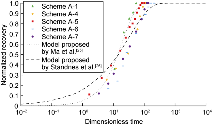
Based on above equation and experimental data, the relationship curve of the dimensionless time versus the normalized recovery (i.e. ratio of actual recovery to the maximum recovery) was plotted as shown in Fig. 21. It can be seen that the experimental data fits well with the classical imbibition scaling equations proposed by Ma et al.[25] and Standnes et al.[26]. This implies the micromodel imbibition follows the same law with the core imbibition, proving the reliability of the micromodel imbibition.
Fig. 21.
Fig. 21.
Relationship curves of the normalized imbibition recovery and dimensionless time in water-wet models.
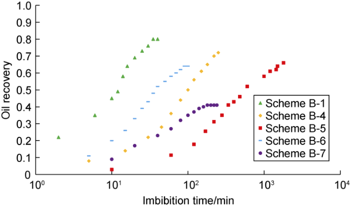
Through imbibition experiments in oil-wet micromodels with different sizes and boundary conditions, it is found that the oil recovery of imbibition under the effect of wettability alteration solution is in linear relation with imbibition time in logarithmic coordinates (Fig. 22).
Fig. 22.
Fig. 22.
Relationship between oil recovery and time during imbibition under the effect of wettability alteration solution in oil-wet micromodels.
Combining with experimental results discussed in previous section, the imbibition under the effect of wettability alteration solution in oil-wet model is still dominated by capillary pressure, thus, the Eq. (2) and Eq. (3) can also be used to fit these experimental data, and the results are shown in Fig. 23. It can be seen that the experimental data fits well with the classic imbibition scaling equation dominated by capillary pressure.
Fig. 23.
Fig. 23.
Relationship between normalized oil recovery and dimensionless time during imbibition under the effect of wettability alteration solution in oil-wet micromodels.
4.2. Gravity dominated imbibition
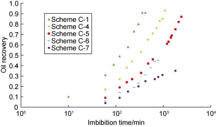
Fig. 24 shows the imbibition results of Winsor III type surfactant solution in oil-wet models with different sizes and boundary conditions. It can be seen that although the imbibition time prolongs, the oil recovery doesn’t decrease significantly with the increase of the model size.
Fig. 24.
Fig. 24.
Imbibition recovery dynamic curves of Winsor III type surfactant solution in oil-wet models.
The imbibition results of micromodels with different sizes are consistent with those of core experiments by Li et al.[13]. The imbibition of Winsor III type surfactant solution can be divided into 2 processes: the migration of oil from the bottom to the top of the model under the effect of buoyancy and ultra-low IFT condition; the middle phase microemulsion formed through the solubilization effect between oil phase and Winsor III type surfactant solution, and then produced through the dilution of excess Winsor III type surfactant solution (rebalance of middle phase microemulsion). However, the formation and dilution of the middle phase microemulsion needs continuous diffusion of the surfactant solution to increase the surfactant solution concentration around the microemulsion, which implies this process takes a long time. When the model is too small in size, most oil in matrix would be produced under the effect of buoyancy, but the residual oil in matrix can’t be solubilized with Winsor III type surfactant solution in such short time and would be trapped in the matrix. In contrast, in the model with larger size, the time that the oil flows from the bottom to the top of the model is long enough for the formation and dilution of middle phase microemulsion, so the residual oil in the model can be recovered through solubilization, and the larger models didn’t decrease significantly in oil recovery.
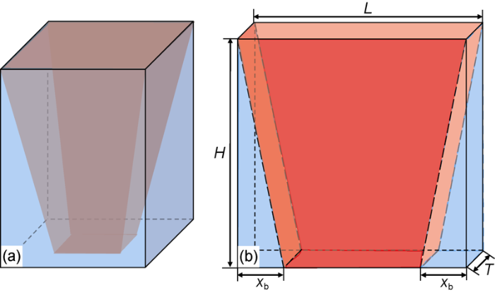
Meanwhile, the boundary conditions have a significant effect on the imbibition oil recovery of the Winsor III type surfactant solution (Fig. 24). The case with one boundary side and two boundary sides open had much lower oil recovery than the case with all boundary sides open, which is consistent with the experimental results of Mejia et al.[27]. That suggests in the imbibition model dominated by gravity with ultra-low IFT, the opening of the top and bottom boundaries have decisive effect on the oil recovery. Li et al.[14] established the recovery scaling equation of imbibition dominated by gravity based the CT scanned images. But different from the 3D pore network of the cores, the 2D microfluidic model is composed of one layer pore channels, as shown in Fig. 25 (red represents area not invaded by water, blue represents area invaded by water). The equations proposed by Li et al. need to be modified.
Fig. 25.
Fig. 25.
Imbibition patterns of 3D core model (a) and 2D model (b) under the effect of Winsor III type surfactant solution.
As shown in Fig. 25, the volume of produced oil is equal to the volume of imbibed water, which can be expressed as:
Combined with Eq. (4), the oil recovery of Winsor III type surfactant solutionin 2D model can be expressed as:
As the derivation processes of the 2D model and 3D model are consistent, the dimensionless time ${{t}_{\text{D2}}}$ can be expressed as Eq. (6) with reference of Li et al.[14]:
Then the relation between the oil recovery and the dimensionless time is as follows:
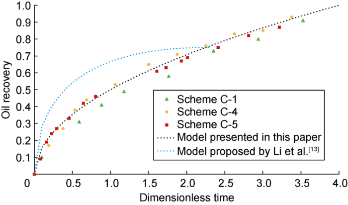
Fig. 26 shows the relationship between dimensionless time and oil recovery of the imbibition under the effect of Winsor III type surfactant solution in the oil-wet models with different sizes. The imbibition model proposed in this paper can describe the imbibition of Winsor III type surfactant solution and oil in 2D model more accurately than the scaling equation proposed by Li et al.[14].
Fig. 26.
Fig. 26.
Imbibition dynamics of oil-wet models under the effect of Winsor III type surfactant solution.
5. Conclusions
During the imbibition of water and oil, the oil flows to the fracture through the Haines jump, and the capillary back pressure is the main resistance blocking oil expulsion from matrix. In the imbibition process of the oil and wettability alteration solution system, the oil expulsion from matrix is still through the Haines jump process, but the reduction of IFT weakens the Haines jump and slows the oil expulsion speed, the small oil droplets formed by emulsification effect of the wettability alteration solution drain from the matrix under the effect of gravity, and the reduction of capillary back pressure improves the imbibition recovery. The imbibition of oil and the Winsor III type surfactant solution goes along with the formation and re-equilibrium of middle phase microemulsion. Three main mechanisms enhancing imbibition recovery in this process are the buoyancy effect under the ultra-low IFT condition, oil solubilization effect during the formation and re-equilibrium of the middle phase microemulsion, and the diffusion effect of the middle phase microemulsion.
The counter-current imbibition of oil-water and oil- wettability alteration solution with low IFT is dominated by capillary pressure, all boundaries of the matrix contribute equally to the ultimate oil recovery, and the oil recovery data fits well with the classic imbibition scaling equation. The imbibition of oil-Winsor III type surfactant solution under ultra-low IFT is a co-current imbibition process, the oil recovery data obtained from the micromodels fits well with the equation proposed in this paper.
Nomenclature
${{A}_{i}}$imbibition area in the i direction, cm2;
gacceleration of gravity, 9.8 m/s2;
Hheight of the matrix, cm;
Kpermeability, 10-3 μm2;
Krmrelative permeability of the middle phase microemulsion;
Lwidth of the matrix, cm;
${{L}_{{{A}_{i}}}}$distance of imbibition front from the open end of the matrix to the close end, cm;
${{L}_{\text{C}}}$characteristic length, cm;
Mmobility ratio of middle phase microemulsion to oil phase;
nnumber of the surfaces between cores and aqueous phase;
${{p}_{\text{n}}}$pressure of the non-wetting phase, mPa;
${{p}_{\text{w}}}$pressure of the wetting phase, mPa;
$r(x)$the radius of the pore at the imbibition front x, m;
${{R}_{\text{G}}}$oil recovery of the gravity dominated imbibition;
${{S}_{\text{oi}}}$original oil saturation, %;
${{S}_{\text{or}}}$residual oil saturation, %;
timbibition time, min;
tDdimensionless time of the capillary pressure dominated imbibition, dimensionless;
tD2dimensionless time of the gravity dominated imbibition, dimensionless;
Tdepth of the pore throat, cm;
Vbvolume of the model, cm3;
xbthe distance between the matrix boundary and the water invasion front, cm;
$\alpha (x)$the contact angle of the pore edge and the local flow direction at the imbibition front x, (°);
βunit conversion factor, 0.019;
γinterfacial tension, mN/m;
δthe parameter characterizing the weaken capillary pressure of 2D models, 0.02;
$\Delta p(x)$pressure drop between the wetting phase and non-wetting phase at the imbibition front x, mPa;
ΔVvolume of water invaded into the matrix, cm3;
Δρdensity difference between the oil phase and water phase, g/cm3;
θcontact angle, (°);
μooil viscosity, mPa•s;
μmviscosity of middle phase microemulsion, mPa•s;
μwwater viscosity, mPa•s;
ϕporosity, %.
Reference
Formation, distribution, potential and prediction of global conventional and unconventional hydrocarbon resources
Development potential and technical strategy of continental shale oil in China
Microfluidic investigation of low-salinity effects during oil recovery: A no-clay and time-dependent mechanism
Experimental study on spontaneous imbibition of recycled fracturing flow-back fluid to enhance oil recovery in low permeability sandstone reservoirs
DOI:10.1016/j.petrol.2018.03.058 URL [Cited within: 1]
Application of nanotechnology in petroleum exploration and development
Characteristics and EOR mechanisms of nanofluids permeation flooding for tight oil
Features and imbibition mechanisms of Winsor I type surfactant solution in oil-wet porous media
New insights into flow physics in the EOR process based on 2.5D reservoir micromodels
DOI:10.1016/j.petrol.2019.106214 URL [Cited within: 4]
Local instabilities during capillary-dominated immiscible displacement in porous media
DOI:10.26804/capi URL [Cited within: 1]
A new scaling equation for imbibition process in naturally fractured gas reservoirs
DOI:10.26804/ager URL [Cited within: 1]
A model of spontaneous flow driven by capillary pressure in nanoporous media
DOI:10.26804/capi URL [Cited within: 1]
Experimental study on spontaneous imbibition characteristics of tight rocks
DOI:10.26804/ager URL [Cited within: 2]
Analysis on the influencing factors of imbibition and the effect evaluation of imbibition in tight reservoirs
DOI:10.1016/S1876-3804(19)60231-4 URL [Cited within: 3]
Scaling of low-interfacial-tension imbibition in oil-wet carbonates
Experimental evaluation of the salt dissolution in inter-salt shale oil reservoirs
Effects of microscopic pore structure heterogeneity on the distribution and morphology of remaining oil
Pore- scale investigation of microscopic remaining oil variation characteristics in water-wet sandstone using CT scanning
DOI:10.1016/j.jngse.2017.04.003 URL [Cited within: 1]
A multi-scale experimental study of hydrophobically-modified polyacrylamide flood and surfactant-polymer flood on enhanced heavy oil recovery
DOI:10.1016/j.petrol.2019.106258 URL [Cited within: 1]
Evaluating the performance of surfactants in enhancing flowback and permeability after hydraulic fracturing through a microfluidic model
DOI:10.2118/199346-PA URL [Cited within: 1]
Formation and flow behaviors of in situ emulsions in heavy oil reservoirs
DOI:10.1021/acs.energyfuels.9b00154 URL [Cited within: 1]
Haines jumps: Pore scale mechanisms
DOI:10.1103/PhysRevE.100.023115 URL [Cited within: 1]
Advances in studies of spontaneous imbibition in porous media
Generalized scaling of spontaneous imbibition data for strongly water-wet systems
DOI:10.1016/S0920-4105(97)00020-X URL [Cited within: 3]
A single-parameter fit correlation for estimation of oil recovery from fractured water-wet reservoirs
DOI:10.1016/j.petrol.2009.12.008 URL [Cited within: 1]
Surfactant flooding in oil-wet micromodels with high permeability fractures
DOI:10.1016/j.fuel.2018.12.076 URL [Cited within: 1]


