

Introduction
At the beginning of the 21st century, the ultra-short radius horizontal drilling technology with coiled tubing and deflector as the core was taken shape preliminarily[1⇓-3]. This technology is mainly applied to the secondary completion for old wells and stimulation for low-yield wells [4⇓-6]. With radial jet drilling technology, the ultra- short radius horizontal wells have the hole size of 25.4- 50.1 mm and the maximum footage up to 90 m. In recent years, the use of rotary drilling flexible drilling tools has increased the hole size of ultra-short radius horizontal wells to 114.0-142.0 mm, and the horizontal footage to 60-100 m [7⇓⇓-10]. The ultra-short radius horizontal wells, with a range of curvature radius of 2-5 m, can be side-tracked from casings of 139.7 mm and 244.5 mm. Several well tests have been carried out in offshore oilfields and coalbed methane fields in China [7⇓-9,11]. Although larger open holes of ultra-short radius horizontal wells can be completed with screen pipes of larger sizes, the extending length of the completion screen pipe is still restricted to friction resistance, so the open hole completion is adopted for ultra-short radius horizontal wells. A kind of screen pipe with slits perpendicular to the casing axis can pass through the bending section of the ultra-short radius horizontal well, but is limited in extending length into the ultra-short radius horizontal section [12]. Shen et al.[13-14] proposed the polyethylene (PE) screen pipe completion for coalbed methane horizontal wells with pumping. In this scheme, the extending length of PE screen pipe (50.8 mm in diameter) running into the horizontal wellbore through drill pipe was 570 m. However, the rotary flexible drilling pipe with complex structure and small inner diameter restricts the size of non-metallic completion screen pipe built-in.
In this paper, the large-size non-metallic composite continuous pipe is selected to process the screen pipe, and the small-size steel coiled tubing is adopted as the inner tubular string to enhance the stiffness of the non-metallic composite continuous screen pipe. In addition, the novel completion tubular string composed of the non-metallic completion screen pipe and the steel coiled tubing is designed to be run in by hydraulic drive to overcome the resistance of axial force transfer and buckling of completion tubular string. Two issues must be solved to establish the hydraulic drive non-metallic screen pipe. Firstly, the innovative design of completion tubular string structure and tools for this technology is required. Secondly, a novel mechanical-hydraulic coupling model needed to be established. In order to address these issues, it is required to systematically design the completion tubular string structure, downhole special tools and technical processes. Then the hydraulic drive model can be introduced into the tubular string mechanical model. Based on the soft rope model [15-16] and rigid model [17], Gao et al. [18-21] deduced the local and integral mechanical models of downhole tubular string, and studied the mechanical behavior of the downhole tubular string in extended- reach wells. Some other researchers examined the mechanical behavior of coiled tubing [22], established the failure limit model of coiled tubing [23], and analyzed the operation ability of coiled tubing in horizontal wells [24-25].
For the ultra-short radius horizontal wells completed by rotary flexible drilling tools, the authors designed completion tools and technology for the non-metallic composite continuous screen pipe. In this technology, the non-metallic composite continuous screen pipe is run into the well by hydraulic drive. However, the non-metallic completion screen pipe is much smaller than the wellbore due to the complex tubular string structure [26-27]. Therefore, this paper proposes a novel design of the completion tubular string structure and tools. Then, the mechanical-hydraulic coupling model is established to quantitatively calculate the extending length of non-metallic composite continuous screen pipe running into ultra-short radius horizontal well. This research provides theoretical guidance for non-metallic completion screen pipe running into ultra-short radius horizontal well by hydraulic drive.
1. Tubular string structure, special tools and technical principle
Facing the challenges of non-metallic completion screen pipe running into ultra-short radius horizontal well, a novel completion tubular string structure composed of guide tubing, hydraulic drive tubing and non-metallic completion screen pipe from inside to outside has been designed. Hydraulic drive tools for this new completion tubular string, including guide shoes, guide tubing centralizer, sliding sealing device, crossover sub etc. have been devised. The guide shoe is applied to connect the hydraulic drive tubing and the non-metallic composite continuous screen pipe. The guide tubing centralizer is adopted to maintain the guide tubing's centrality in the hydraulic drive tubing. The sliding sealing device is the core device to maintain the sliding seal between the hydraulic drive tubing and the guide tubing. The upper tubing and the lower completion tubular string are connected by the crossover sub. The hydraulic drive completion tubular string can form hydraulic load on the guide shoe to tow the completion tubular string into the ultra-short radius horizontal well. This novel method solves the difficulties of axial force transmission and string buckling in the process of the completion tubular string running into the ultra-short radius horizontal well.
1.1. Structure design and operation principle
Casing sidetracking in different directions from bottom to top can complete by deflector controlling the rotary flexible drilling trajectory [8], in which casing window length is about 0.2 m and sidetracking window spacing is about 0.6 m. Multiple ultra-short radius horizontal wells with different directions can increase the control area of the target reservoir [7]. Drilling to the design well depth, the flexible drilling tools are pulled out of the hole and the deflector is temporarily detained in the casing to support the hydraulic drive non-metallic composite continuous screen pipe running into single ultra-short radius horizontal well. The structure of the completion tubular string is shown in Fig. 1 a. The completion tubular string consists of three layers: the outer layer is non-metallic composite continuous screen string, which is composed of guide shoe, non-metallic composite continuous screen pipe and screen pipe centralizers; the middle layer is a hydraulic drive string, which is composed of a hydraulic drive tubing (coiled tubing) and a sliding sealing device; and the inner layer is the guide tubular string, which is composed of centralizer and guide tubing (coiled tubing). The guide tubing and the upper tubing are connected through the crossover sub. Before the completion tubular string is run into the open hole, a sealing space filled with air is formed between the hydraulic drive tubing, guide shoe, guide tubing and the crossover sub by the sliding sealing device. When the hydraulic sleeve in the crossover sub is open under hydraulic pressure, the hydraulic drive tubing and the non-metal composite continuous screen pipe slide toward the bottom hole under gravity with the air in the completion tubular string gradually replaced by liquid. When the hydraulic drive tubing and non-metallic composite continuous screen pipe are blocked, the hydraulic drive process is started, in which hydraulic pressure is transmitted to the hydraulic drive tubing through the guide tubing, and the hydraulic drive tubing and the non-metallic composite continuous screen pipe move synchronously toward the bottom hole under the traction force on guide shoe formed by hydraulic pressure. In the process of guiding the hydraulic drive tubing to move, the guide tubing always maintains a sliding sealing state with the sliding sealing device. At the same time, the friction resistance between the guide tubing and the sliding sealing device at the end of the hydraulic drive tubing can avoid helical buckling of the hydraulic drive tubing in the vertical section. The hydraulic tubing is immediately braked once the sliding sealing device contacts with the guide tubing centralizer. However, the non-metallic composite continuous screen pipe still moves forward under the traction force on the guide shoe. The separation of the hydraulic drive tubing and the guide shoe is completed as the pins and metal wires in the guide shoe are cut off. Moreover, the blades retracting in the guide shoe open and fix on the wellbore as the metal wires are cut off, fixing the non-metallic composite continuous screen pipe in the ultra-short radius horizontal well. The sudden drop of pump pressure indicates that the hydraulic drive tubing is separated from the guide shoe successfully. Then, the tubing, guide tubing, hydraulic drive tubular string and accessories are pulled out of hole and the completion with non-metallic completion screen pipe for single ultra-short radius horizontal well is accomplished by hydraulic drive. With this technology, non-metallic composite continuous screen pipe with a diameter of 100 mm and wall thickness of 20 mm can be run into the open hole of ultra-short radius horizontal well with a diameter of 116 mm.
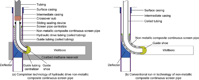
Fig. 1. Schematic diagram of completion tubular string structure for ultra-short radius horizontal wells. |
The conventional run-in method of non-metallic composite continuous screen pipe in ultra-short radius horizontal well is shown in Fig. 1 b, in which the non-metallic composite continuous screen pipe is pushed into horizontal section by inserted coiled tubing. This process is simple, but the axial force transmission efficiency is low during the process of completion tubular string running. The extending length of non-metallic composite continuous screen pipe into ultra-short radius horizontal well is restricted due to the buckling of coiled tubing and non-metallic composite continuous screen pipe. Based on an engineering case, the extending limits of non-metallic composite continuous screen pipe run into a horizontal well by hydraulic drive technology and conventional technology will be calculated respectively and compared.
1.2. Key devices
1.2.1. Guide shoe
Light weight and high strength alloy aluminum material is adopted in guide shoe body. The front end of the non-metallic composite continuous screen pipe is extended into the guide shoe groove and connected with the guide shoe through the locking device. The hydraulic drive tubing, guide shoe and blades are connected by pins with built-in metal wires. Before the hydraulic drive tubing separates from the guide shoe, four blades are retracted inside the guide shoe, as shown in Fig. 2 a. After the hydraulic drive tubing is separated from the guide shoe, the four blades are opened and fixed on the open hole wall, as shown in Fig. 2 b.
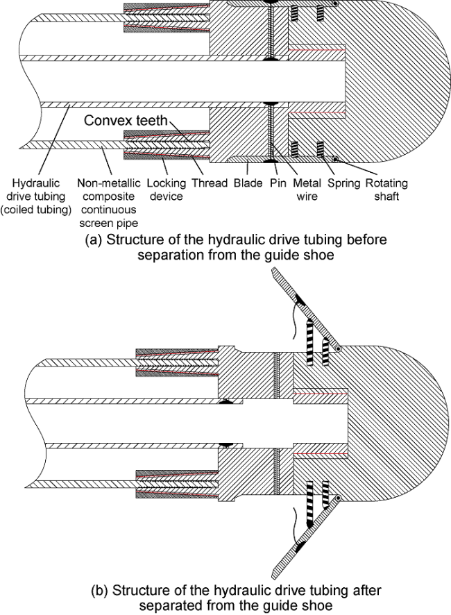
Fig. 2. Schematic diagram of guide shoe structure. |
1.2.2. Guide tubing centralizer and sliding sealing device
As shown in Fig. 3 , the guide tube centralizer is connected to the front end of the guide tube through four bolts. The four wings of the guide tube centralizer are made of Polytetrafluoroethylene (PTFE) material with low friction and wear resistance. The centralizer can maintain the centrality of the guide tubing in the hydraulic drive tubing to reduce the friction resistance between them.
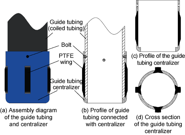
Fig. 3. Schematic diagram of the guide tubing centralizer. |
As shown in Fig. 4 , the sliding sealing device body is made of tempered steel, and the seal unit is made of rubber with high strength, high toughness and high wear resistance. The sliding sealing device and hydraulic drive tubing are connected at the wellhead, as shown in Fig. 5 a. The hydraulic fluid enters the sealing cavity through No. 1 and No. 2 inlets, and the rubber cylinder expands under hydraulic pressure and forms a seal with the guide tubing, as shown in Fig. 5 b. When the pressure of the sealing chamber reaches the designed value, the injection of hydraulic fluid is stopped. The No.1 and No.2 inlets are closed as the metal sealing balls inside reset under the spring elastic force, as shown in Fig. 5 c. The hydraulic drive tubing is immediately braked once the sliding sealing device contacts with the guide tubing centralizer, as shown in Fig. 5 d. Pull the hydraulic drive device out of the hole and open the pressure relief channel to release the pressure in the sealing chamber to allow the rubber units to reset (Fig. 5 e) when the completion is done. Remove the sliding sealing device from hydraulic drive tubing, as shown in Fig. 5 f.
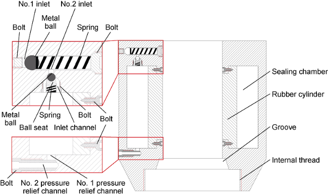
Fig. 4. Structure diagram of sliding sealing device. |
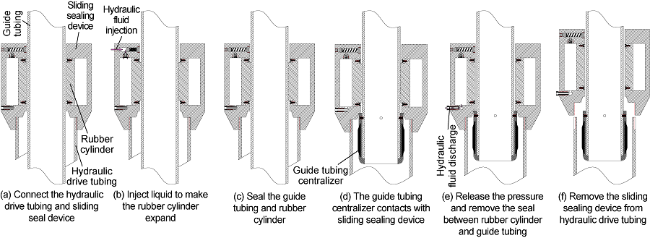
Fig. 5. Working principal diagram of the sliding sealing device. |
1.2.3. The crossover sub and non-metallic composite continuous screen pipe
Before the guide shoe reaches the sidetracking position in casing, the built-in hydraulic sleeve of the crossover sub remains closed to isolate the air in the lower completion tubular string from the water in the upper tubing, as shown in Fig. 6 a. When the guide shoe reaches the sidetracking position in casing, water is pumped into the tubing until the sliding sleeve is opened under hydraulic pressure, as shown in Fig. 6 b. The hydraulic drive tubing and the non-metal composite continuous screen pipe slide to the bottom hole under gravity as the air in the completion tubular string is gradually replaced by water from upper tubing.

Fig. 6. Schematic diagram of the crossover sub. |
The ultra-short radius horizontal well adopted the typical non-metallic composite continuous pipe used in the oil and natural gas industry. As shown in Fig. 7 , the non-metallic composite continuous pipe is composed of the inner liner, reinforcing layer, the tensile layer and the outer sheath [15,28 -29]. With a minimum working bending radius of 0.6 m, the non-metallic composite continuous pipe can pass through the bending section of ultra-short radius horizontal well [30]. Compared with common tubing and casing, non-metallic composite continuous pipe has the characteristics of good flexibility, high strength, low friction coefficient, anti-scaling and corrosion resistance [31]. Slits were cut and holes were drilled by hydraulic cutting technology on the non-metallic composite continuous pipe to get the non-metallic composite con-tinuous screen pipe.

Fig. 7. Photos of non-metallic composite continuous pipe. |
1.3. Completion process of hydraulic drive non-metallic composite continuous screen pipe
(1) With air filling the sealing space in the completion tubular string below the crossover sub and water filling the tubing above the crossover sub, the completion tubular string is conveyed to the sidetracking position inside casing by tubing, as shown in Fig. 8 a. (2) Stop the pumping water immediately once the built-in sliding sleeve of the crossover sub is opened under hydraulic pressure. During the process of the water in the upper tubing enters the completion tubular string to displace the air, the non-metallic composite continuous screen pipe and hydraulic drive tubing move toward the well bottom under gravity until stopping due to friction resistance, as shown in Fig. 8 b. (3) Start the operation of hydraulic drive non-metal composite continuous screen pipe. The hydraulic drive tubing is braked once the sliding sealing device contacts with the guide tubing centralizer. The hydraulic drive tubing is separated from the guide shoe when the pins and wires inside the guide shoe are cut off by the movement of the guide shoe and the non-metallic composite continuous screen pipe. At the same time, the blades retracting in the guide shoe are opened and fix the non-metallic composite continuous screen pipe in the ultra-short radius horizontal well, as shown in Fig. 8 c. (4) The drilling fluid in the well hole is displaced by water pumped through the tubular string to reduce reservoir damage, as shown in Fig. 8 d.
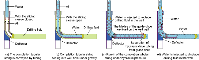
Fig. 8. Flow chart of hydraulic drive non-metallic composite continuous screen pipe running into ultra-short radius horizontal well. |
2. Mechanical-hydraulic coupling model
Based on the special completion tubular string structure composed of hydraulic drive tubing and non-metallic composite continuous screen pipe, a novel mechanical-hydraulic coupling model has been deduced by introducing the Pascal principle and hydraulic drive principle into the tubular string mechanical model. Taking the wellbore structure, tubular string stress, safe pump pressure and critical tubular string sliding velocity as constraints, the extending length of hydraulic drive non-metallic composite continuous screen pipe running into ultra-short radius horizontal well is calculated by finite difference method.
2.1. Tubular string mechanical model
The assumptions are as follows: (1) The soft rod model is adopted for the completion tubular string. (2) The outer wall of the completion tubular string and the wellbore are fully contacted and have the same curvature. (3) Ignore the shear force on the tubular string. (4) The end of the tubular string close to the wellhead is defined as the back end, and the end of the tubular string at well bottom is the front end.
2.1.1. Axial force and side force on the tubular string
The bending section of ultra-short radius horizontal well is shorter than horizontal footage, which can be simplified as two-dimensional wellbore trajectory to calculate the axial force and side force on the completion tubular string.
The differential equation of axial force on the tubular string is as follows [32]:
$\text{d}{{T}_{i}}=\left[ \left( \mu \sin {{\theta }_{i}}-\cos {{\theta }_{i}} \right)\rho g{{A}_{\text{c}}}+{{f}_{\text{c}i}} \right]\text{d}{{l}_{i}}$ (i=1, 2, …, n+1)
${{T}_{i}}=E{{A}_{\text{c}}}\frac{\partial {{u}_{i}}}{\partial {{l}_{i}}}$
From Eqs. (1) and (2), Eq. (3) is obtained:
$\frac{{{\partial }^{2}}{{u}_{i}}}{\partial {{l}_{i}}^{2}}=\frac{\left( \mu \sin {{\theta }_{i}}-\cos {{\theta }_{i}} \right)\rho {{A}_{\text{c}}}g+{{f}_{\text{c}i}}}{E{{A}_{\text{c}}}}$
The finite difference scheme of Eq. (3) is as follows:
$u_{i+1,j}^{{}}-2u_{i,j}^{{}}+u_{i-1,j}^{{}}=\frac{\left( \mu \sin {{\theta }_{i,j}}-\cos {{\theta }_{i,j}} \right)\rho {{A}_{\text{c}}}g+{{f}_{\text{c}i,j}}}{E{{A}_{\text{c}}}}\text{d}{{l}^{2}}$ (j=1, 2, …, m)
In Eq. (4), if i=1 and j1, fci,j=Fc/dli, otherwise fci,j=0.
The initial condition of finite difference calculation is as follows:
$u_{0,j}^{{}}=j\text{d}l$
The boundary condition is as follows:
$EA\frac{u_{n+1,j}^{{}}-u_{n,j}^{{}}}{\text{d}l}=\left\{ \begin{matrix} 0\quad \quad \quad \quad j=1 \\ {{T}_{\text{r}}}\left( j-1 \right)\quad j\ne 1 \\\end{matrix} \right.$
The side force on the completion tubular string is calculated as follows [15]:
${{F}_{\text{n}}}=\sqrt{{{\left( \text{d}T\Delta \alpha \sin \overline{\theta } \right)}^{2}}+{{\left( \text{d}T\Delta \theta +W\sin \overline{\theta } \right)}^{2}}}$
The frictional force between completion tubular string and well wall is calculated as follows:
${{F}_{\text{d}}}={{F}_{\text{n}}}\mu $
2.1.2. The forces on sliding sealing device and guide shoe
The hydraulic pressure on the sliding sealing device is equal to that on the guide shoe, but the direction is opposite. The force formed by the inner and outer hydraulic pressure difference coincides with the tubular string axis. The forces on guide shoe and sliding sealing device are calculated as follows:
$F\text{=}\frac{\pi {{p}_{\text{s}}}\left( {{d}_{\text{hi}}}^{2}-{{d}_{\text{go}}}^{2} \right)}{4}$
${{F}_{\text{s}}}=\frac{\pi {{p}_{\text{s}}}d{{_{\text{hi}}^{{}}}^{2}}}{4}$
The sliding friction force between guide tubing and the built-in rubber cylinder of sliding sealing device is calculated as follows:
${{F}_{\text{c}}}={{N}_{\text{c}}}{{\mu }_{\text{c}}}=ql-{{F}_{\text{hel}}}$
2.2. Hydraulic drive model
The assumptions are as follows: (1) The fluid volume is incompressible. (2) The whole tubular string is in an ideal sealing state. (3) No formation leakage. (4) The friction resistance is Coulomb friction. (5) The local pressure loss of fluid flowing in the tubular string is not considered. (6) The fluid in the tubular string is water.
2.2.1. Hydraulic load on completion tubular string
Hydraulic traction force driving the completion tubular string is calculated as follows:
${{T}_{\text{r}}}={{F}_{\text{c}}}+{{F}_{\text{d}}}-{{W}_{\text{p}}}$
This traction force is equal to the hydraulic load on the guide shoe, so the calculation formula for hydraulic pressure on the guide shoe is as follows:
${{p}_{\text{s}}}=\frac{{{T}_{\text{r}}}}{{{A}_{\text{h}}}}$
2.2.2. Pressure loss of the tubular string
Based on the fluid continuity equation, the average velocities of fluid in pipes of different diameters are calculated.
${{v}_{1}}{{A}_{1}}={{v}_{2}}{{A}_{2}}={{q}_{\text{f}}}$
where ${{A}_{1}}=\frac{\pi {{d}_{1}}^{2}}{4}$ ${{A}_{2}}=\frac{\pi {{d}_{2}}^{2}}{4}$
As the water adopted in hydraulic driving non-metallic completion tubular string is approximately Newtonian fluid, Reynolds number calculation formula of the fluid flowing in the pipe is as follows:
$R{{e}_{1}}=\frac{{{v}_{1}}{{d}_{1}}{{\rho }_{\text{f}}}}{\gamma }$
$R{{e}_{2}}=\frac{{{v}_{2}}{{d}_{2}}{{\rho }_{\text{f}}}}{\gamma }$
The following is the calculation formula of liquid flow friction coefficient in the pipe [33]:
${{f}_{1}}=\frac{a}{R{{e}_{\text{1}}}^{b}}$
${{f}_{2}}=\frac{a}{R{{e}_{2}}^{b}}$
where, if Re1≤2000 or Re2≤2000, a=16, b=1. If Re1> 2000 or Re2>2000, a=0.078 6, b=0.25.
The pressure loss of fluid flowing in the pipe can be obtained from the following equation [34]:
$\Delta p=\frac{2{{f}_{1}}{{\rho }_{\text{f}}}{{l}_{1}}{{v}_{1}}^{2}}{{{d}_{1}}}\text{+}\frac{2{{f}_{2}}{{\rho }_{\text{f}}}{{l}_{2}}{{v}_{2}}^{2}}{{{d}_{2}}}$
2.3. Constraint conditions
The constraint conditions mainly include the critical load of helical buckling of tubular string, the safe working pressure of the pump (48.0 MPa), the critical run-in velocity of completion tubular string, the minimum bending radius of coiled tubing, the stress on the completion tubular string calculated from Mises strength criterion, the ultra-short radius horizontal well structure and curvature radius.
Ignoring the effect of additional friction force caused by sinusoidal buckling of tubular string, the critical load of tubular string helical buckling in vertical section is calculated by the following formula [35]:
${{F}_{\text{hel}}}=5.55{{\left( EI{{q}^{2}} \right)}^{\frac{1}{3}}}$
Calculation formula of tubular string critical helical buckling load in the bending well section is [36]:
${{F}_{\text{hel}}}=\frac{12EI}{{{r}_{\text{c}}}R}\left( 1+\sqrt{1+\frac{{{r}_{\text{c}}}{{R}^{2}}q\sin \theta }{8EI}} \right)$
The calculation formula of tubular string helical buckling load in horizontal section is as follows [37]:
${{F}_{\text{hel}}}=2\left( 2\sqrt{2}-1 \right)\sqrt{\frac{EIq\sin \theta }{{{r}_{\text{c}}}}}$
When blocked suddenly during high speed movement, the completion tubular string may have helical buckling or even self-locking. The critical run-in velocity of coiled tubing in the hydraulic drive process is calculated by using the hydraulic drive tubing critical helical buckling load in the horizontal section.
$v\le C\sqrt{\frac{2}{\rho E}}\frac{{{F}_{\text{hel}}}}{{{A}_{\text{c}}}}$
Both the hydraulic drive tubing and guide tubing are coiled tubing, and the minimum bending radius of them within the elastic deformation range can be calculated by the following equation:
$d=\frac{2{{R}_{\min }}{{\sigma }_{\text{s}}}}{E}$
3. Calculation and analysis of engineering case
In 2017, sidetracking ultra-short radius horizontal well test was completed in a deep CBM vertical well in the eastern margin of Ordos Basin. The production casing of this well had an outer diameter of 139.7 mm, a wall thickness of 7.72 mm and set depth of 1968.1 m. The well was sidetracked at the depth of about 1900.0 m. The horizontal well sidetracked had a borehole diameter of 114.0 mm, a horizontal footage of about 100.0 m, and was completed as open hole. Based on structure of this well and the mechanical-hydraulic coupling model, the extending length of the hydraulic drive completion tubular string was calculated. In order to quantitatively calculate the extending limit of hydraulic drive completion tubular string, it was assumed that the horizontal footage of the ultra-short radius horizontal well was infinite.
3.1. Structural design of completion tubular string in ultra-short radius horizontal well
Based on the formula of the minimum elastic bending radius (Eq. (23)), three series of hydraulic drive completion tubular string structures for ultra-short radius horizontal wells with different curvature radii were designed according to the specifications and parameters of coiled tubing of Halliburton Company, as shown in Table 1 . A non-metallic composite continuous screen pipe suitable for sidetracked ultra-short radius horizontal wells with outer diameter of 139.7 mm was designed with an outer diameter of 100 mm, a wall thickness of 20 mm, and a density of 1600 kg/m3, which was fiber reinforced composite tube and suitable for well with temperature no more than 90 °C [38-39].
Table 1. Combination schemes of hydraulic drive tubing and guide tubing |
| No. | Completion string structure | Steel grade | Material | Yield strength/ kPa | Elastic modulus/kPa | Density/ (kg·m-3) | Outer Diameter/ mm | Inner Diameter/ mm | Minimum elastic bending radius/m |
|---|---|---|---|---|---|---|---|---|---|
| 1# | Guide tubing | CT-90 | A-606Type4MOD | 620 528.2 | 206 842 719.8 | 7849 | 19.05 | 14.05 | 4.8 |
| Hydraulic drive tubing | CT-100 | A-606Type4MOD | 689 475.7 | 206 842 719.8 | 7849 | 31.75 | 27.69 | ||
| 2# | Guide tubing | CT-90 | A-606Type4MOD | 620 528.2 | 206 842 719.8 | 7849 | 12.70 | 7.70 | 3.8 |
| Hydraulic drive tubing | CT-100 | A-606Type4MOD | 689 475.7 | 206 842 719.8 | 7849 | 25.40 | 21.34 | ||
| 3# | Guide tubing | CT-90 | A-606Type4MOD | 620 528.2 | 206 842 719.8 | 7849 | 12.70 | 7.70 | 3.2 |
| Hydraulic drive tubing | CT-100 | A-606Type4MOD | 689 475.7 | 206 842 719.8 | 7849 | 19.05 | 14.05 |
3.2. Numerical calculation
3.2.1. Extending length of non-metallic composite screen pipe by conventional technology
Basic parameters: drilling fluid density of 1050 kg/m3, water density and viscosity of 1000 kg/m3 and 1.000 5 Pa•s, respectively.
Coiled tubing size, curvature radius of ultra-short radius horizontal well and friction coefficient between non-metallic composite screen pipe and well wall were the main factors affecting the extending length of non- metallic composite screen pipe by conventional technology. Based on the three factors, orthogonal analysis designs were made, as shown in Table 2 . Based on the orthogonal analysis, the extending limits of completion tubular string running into the ultra-short radius horizontal well in the designed schemes were calculated with the three factors as variables, as shown in Table 3 .
Table 2. Orthogonal designs of the controlling factors of non-metallic composite screen pipe extending length for conventional technology |
| Level | Factor | ||
|---|---|---|---|
| Coiled tubing size/mm | Curvature radius of wellbore/m | Friction coefficient | |
| 1 | 19.05 | 3.2 | 0.2 |
| 2 | 25.40 | 3.8 | 0.3 |
| 3 | 31.75 | 4.8 | 0.4 |
Table 3. Numerical calculation results of non-metallic composite screen pipe extending length with conventional technology |
| No. | Size of coiled tubing/mm | Curvature radius of wellbore/m | Friction coefficient | Extending limit/m |
|---|---|---|---|---|
| 1 | 19.05 | 3.20 | 0.20 | 25 |
| 2 | 19.05 | 3.80 | 0.30 | 15 |
| 3 | 19.05 | 4.80 | 0.40 | 11 |
| 4 | 25.40 | 3.20 | 0.30 | 18 |
| 5 | 25.40 | 3.80 | 0.40 | 12 |
| 6 | 25.40 | 4.80 | 0.20 | 32 |
| 7 | 31.75 | 3.20 | 0.40 | 13 |
| 8 | 31.75 | 3.80 | 0.20 | 36 |
| 9 | 31.75 | 4.80 | 0.30 | 21 |
Range analysis of the numerical calculation results is shown in Table 4 . The results show that the factors influencing the extending length of non-metallic composite continuous screen pipe by conventional technology in descending order are friction coefficient, coiled tubing size and well curvature radius. Variance analysis of the numerical results are shown in Table 5 . The results show that the friction coefficient has the most obvious influence on the extending length of non-metallic composite continuous screen pipe by conventional technology, while coiled tubing size and well curvature radius have relatively insignificant effects on that. Based on the results of range analysis and variance analysis, it can be seen that the extending limit of non-metallic composite continuous screen pipe by conventional technology is 37 m in the optimal design scheme, namely at the coiled tubing diameter of 31.75 mm, the wellbore curvature radius of 4.8 m, and friction coefficient of 0.2.
Table 4. Range analysis of numerical calculation results of non-metallic composite screen pipe extending length for conventional technology |
| Factor | K1/m | K2/m | K3/m | k1/m | k2/m | k3/m | r/m |
|---|---|---|---|---|---|---|---|
| Coiled tubing size | 51 | 62 | 70 | 17.00 | 20.67 | 23.33 | 6.33 |
| Wellbore curvature radius | 56 | 63 | 64 | 18.67 | 21.00 | 21.33 | 2.67 |
| Friction coefficient | 93 | 54 | 36 | 31.00 | 18.00 | 12.00 | 19.00 |
Note: K1, K2 and K3 are the sum of extending limits of a certain factor at levels 1, 2 and 3. Taking the Level 1 (19.05 mm) of the coiled tubing size as an example, K1 = 25 + 15 + 11 = 51 m. k1, k2, k3 are the average value of extending lengths of a certain factor at levels 1, 2 and 3, respectively. Taking the Level 1 (19.05 mm) of the coiled tubing size as an example, k1=K1/3=17 m. r is the range, r=max (k1, k2, k3)-min (k1, k2, k3). |
Table 5. Variance analysis of numerical calculation results of non-metallic composite screen pipe extending length for conventional technology |
| Source | Sums of squared deviations | Degree of freedom | Mean square | Value of significant difference level | Significance |
|---|---|---|---|---|---|
| Coiled tubing size | 60.67 | 2 | 30.33 | 7.00 | Not significant |
| Wellbore curvature radius | 12.67 | 2 | 6.33 | 1.46 | Not significant |
| Friction coefficient | 566.00 | 2 | 283.00 | 65.31 | Significant |
| Error | 8.67 | 2 | 4.33 | ||
| Total | 648.01 | 8 | 323.99 |
3.2.2. The extending length of hydraulic drive non-metallic composite continuous screen pipe
Basic parameters: drilling fluid density of 1050 kg/m3, water density and viscosity of 1000 kg/m3 and 1.000 5 Pa•s, respectively. The ultra-short radius horizontal well with curvature radius of 4.8 m was taken as an example, and the completion tubular string was conveyed to the sidetracking window in the casing of vertical well by 60.3 mm tubing.
Structure of completion tubular string, injection flow rate and friction coefficient between the non-metallic composite screen pipe and wellbore are the main factors affecting the extending length of hydraulic driving non-metallic composite screen pipe. Orthogonal schemes of the three factors as shown in Table 6 were designed and analyzed. Based on the orthogonal schemes, the extending limits of non-metallic composite screen pipe running into the ultra-short radius horizontal well were calculated with the three factors as variables, and the results are shown in Table 7 .
Table 6. Orthogonal designs of the controlling factors of hydraulic drive non-metallic composite screen pipe extending length |
| Level | Factor | ||
|---|---|---|---|
| Completion tubular string structure | Injection flow rate/(L·min-1) | Friction coefficient | |
| 1 | 1# | 1 | 0.2 |
| 2 | 2# | 3 | 0.3 |
| 3 | 3# | 6 | 0.4 |
Table 7. Calculation results of extending length of hydraulic drive non-metallic composite screen pipe |
| No. | Structure of completion tubular string | Injection flow rate/(L·min-1) | Friction coefficient | Extending limit/m |
|---|---|---|---|---|
| 1 | 1# | 1 | 0.2 | 655 |
| 2 | 1# | 3 | 0.3 | 510 |
| 3 | 1# | 6 | 0.4 | 379 |
| 4 | 2# | 1 | 0.3 | 301 |
| 5 | 2# | 3 | 0.4 | 228 |
| 6 | 2# | 6 | 0.2 | 381 |
| 7 | 3# | 1 | 0.4 | 250 |
| 8 | 3# | 3 | 0.2 | 427 |
| 9 | 3# | 6 | 0.3 | 333 |
The range analysis of numerical calculation results is shown in Table 8 . The results show that the structure of completion tubular string has the most significant influence on the extending length of hydraulic driving non-metallic composite continuous screen pipe, friction coefficient comes second, and injection flow rate has the smallest influence. Variance analysis of the numerical calculation results is shown in Table 9 . The results show that friction coefficient and completion tubular string structure have obvious influence on the extending length of hydraulic drive non-metallic composite continuous screen pipe, while injection flow rate has relatively insignificant effect. Based on the results of range analysis and variance analysis, it can be seen that the extending limit of hydraulic drive non-metallic composite continuous screen pipe is 655.0 m under the optimal design, which adopts 1# completion tubular string structure and adjusts the injection flow rate and friction coefficient of 1 L/min and 0.2, respectively.
Table 8. Range analysis of numerical calculation results of hydraulic drive non-metallic composite screen pipe extending length |
| Factor | K1/m | K2/m | K3/m | k1/m | k2/m | k3/m | r/m |
|---|---|---|---|---|---|---|---|
| Completion tubular string structure | 1 544 | 910 | 1 010 | 514.67 | 303.33 | 336.67 | 211.33 |
| Injection flow rate | 1 206 | 1 165 | 1 093 | 402.00 | 388.33 | 364.33 | 37.67 |
| Friction coefficient | 1 463 | 1 144 | 857 | 487.67 | 381.33 | 285.67 | 202.00 |
Table 9. Variance analysis of numerical calculation results of hydraulic drive non-metallic composite screen pipe extending length |
| Source | Sums of squared deviations | Degree of freedom | Mean square | Value of significant difference level | Significance |
|---|---|---|---|---|---|
| Completion tubular string structure | 77 456.89 | 2 | 38 728.44 | 37.35 | Significant |
| Injection flow rate | 2181.56 | 2 | 1090.78 | 1.05 | Insignificant |
| Friction coefficient | 61 262.89 | 2 | 30 631.44 | 29.54 | Significant |
| Error | 2073.56 | 2 | 1036.78 | ||
| Total | 142 974.89 | 8 | 71 487.44 |
3.3. Applicability analysis of hydraulic drive completion tubular string
As shown in Table 1 , the gap between the hydraulic drive tubing and the guide tubing in the 3# completion tubular string is only 0.675 mm, which is difficult to install the sliding sealing device and centralizer. So only 1# and 2# completion tubular strings are taken into consid-eration. As shown in Table 10 , the maximum run-in velocities of 1# and 2# completion tubular strings are 39.81 m/min and 31.35 m/min, respectively, and the corresponding maximum injection flow rates are 7.54 L/min and 4.67 L/min, respectively. The minimum wellbore curvature radii of 1# and 2# completion tubular strings are 4.8 m and 3.8 m respectively, extending limits of them are 655 m and 381 m, and the corresponding lower limits of injection flow rates are 1.5 L/min and 0.5 L/min, respectively.
Table 10. Applicable conditions of hydraulic drive completion tubular string |
| Sidetracking casing size/ mm | Open hole size/ mm | Outer diameter of non-metallic composite continuous screen pipe/mm | Structure of completion tubular string | Outer diameter of hydraulic drive tubing/ mm | Outer diameter of guide tubing/mm | Wellbore curvature radius/m | Critical run-in velo- city of completion tubular string/ (m·min-1) | Injection flow rate/ (L·min-1) | Extending limit/m |
|---|---|---|---|---|---|---|---|---|---|
| 139.7 | ≥114 | ≥100 | 1# | 31.75 | 19.05 | ≥4.8 | 39.81 | 1.50-7.54 | 655 |
| 2# | 25.40 | 12.70 | ≥3.8 | 31.35 | 0.50-4.67 | 381 |
3.4. Mechanical and hydraulic analysis of completion tubular string
Basic parameters: 1# completion tubular string structure in Table 1 is adopted and the wellbore curvature radius is 4.8 m. Drilling fluid density is 1050 kg/m3, water density and viscosity are 1000 kg/m3 and 1.000 5 Pa•s, respectively. The friction coefficient between non-metallic composite continuous screen pipe and the well wall is 0.2, and the injection flow rate of hydraulic drive completion tubular string is 1.5 L/min. The completion string is conveyed to the sidetracking window inside casing by 60.3 mm outer diameter tubing.
Based on the mechanical-hydraulic coupling model proposed in this paper, the extending length and pressure loss of hydraulic drive non-metallic composite continuous screen pipe running into ultra-short radius horizontal wells were calculated by finite difference method. The traction force on the guide shoe and downhole string pressure loss are shown in Fig. 9 . The hydraulic drive tubing and the non-metallic composite continuous screen pipe stopped moving after extending 36 m into the ultra-short radius horizontal well under self-weight without hydraulic driving. The pumping pressure remained zero during this process. The traction force on the guide shoe gradually increased after the program of hydraulic drive composite tubular string was started. Subsequently, the completion tubular string moved toward the well bottom again once the traction force exceeded the friction resistance. The extending limit of the completion tubular string was 655 m when the pressure loss of downhole string reached 48 MPa and the traction force on the guide shoe reached 13 663.06 N.
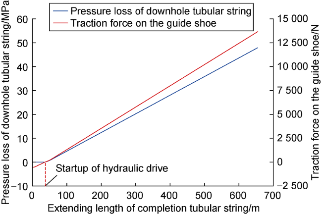
Fig. 9. Pressure loss of downhole string and traction force variation on the guide shoe with extending length. |
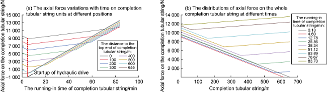
In the process of hydraulic drive completion tubular string running into ultra-short radius horizontal wells, the axial force variations with time of completion tubular string units at different positions are shown in Fig. 10 a, and the axial force distributions on the whole completion tubular string at different times are shown in Fig. 10 b. Before starting hydraulic drive, the completion tubular string ran into the horizontal section under self-weight, the axial force of the completion tubular string decreased gradually, while the friction resistance increased gradually, and the completion tubular string entered into the horizontal section changed from tensile state to compressive state. After starting hydraulic drive, traction force on the guide shoe gradually increased, the completion tubular string moved toward the well bottom once the traction force on the guide shoe exceeded the friction resistance between the completion tubular string and the well wall, and changed from compressive state to tensile state. There was no helix buckling during the completion tubular string running-in.
Fig. 10. Axial force curves of the completion tubular string. |
4. Conclusions
Based on the hydraulic drive non-metallic completion composite continuous screen pipe technology for ultra- short radius horizontal wells, the completion tubular string structure is optimized with three-layer strings from inside to outside as follows: guide tubing, hydraulic drive tubing and non-metallic composite continuous screen pipe. Supporting tools for the hydraulic drive technology, including guide shoes, guide tubing centralizer, sliding sealing device, crossover sub, etc. are designed. Non-metallic composite continuous screen pipe completion running into the ultra-short radius horizontal well can be achieved by the hydraulic drive technology and the novel design of completion tubular string structure, which can keep borehole stability. An innovative mechanical-hydraulic coupling model is established by introducing hydraulic model into the tubular mechanical model to provide theoretical guidance for design and control of hydraulic drive non-metallic composite continuous screen pipe running into ultra-short radius horizontal wells.
Based on the wellbore structure of a coalbed methane ultra-short radius horizontal well, the extending limit of non-metallic composite continuous screen pipe by conventional technology is 37 m, while that for hydraulic drive technology is 655 m calculated through mechanical-hydraulic coupling model. Hydraulic drive technology can effectively enhance the extending length of completion tubular string in ultra-short radius horizontal well. Orthogonal analysis results of three factors show that the structure of completion tubular string and the friction coefficient between the non-metallic composite continuous screen and the wellbore are the two factors that have the greatest influence on the extending length of the hydraulic driving non-metallic composite continuous screen pipe in ultra-short radius horizontal well.
Two series of hydraulic drive completion tubular string structures suitable for ultra-short radius horizontal wells under different conditions are optimized, and the extending limits of those completion tubular strings are 381 m and 655 m, respectively.
Nomenclature
a, b—calculation coefficient;
A1—inner sectional area of tubing, m2;
A2—inner sectional area of guide tubing, m2;
Ac—sectional area of completion tubular string, m2;
Ah—inner sectional area of hydraulic drive tubing, m2;
C—safety factor, 0.7≤C≤1.0, dimensionless;
d—outer diameter of coiled tubing, m;
d1—inner diameter of tubing, m;
d2—inner diameter of guide tubing, m;
dgo—outer diameter of guide tubing, m;
dhi—inner diameter of hydraulic drive tubing, m;
E—elastic modulus of completion tubular string, Pa;
f1—friction coefficient of fluid flowing in tubing, dimensionless;
f2—friction coefficient of fluid flowing in guide tubing, dimensionless;
fc—sliding friction on completion tubular string per unit length, N/m;
F—traction force on the guide shoe, N;
Fc—sliding friction, N;
Fd—friction between completion tubular string and wellbore, N;
Fhel—critical buckling load of completion tubular string, N;
Fn—side force on completion tubular string micro-unit, N;
Fs—force on the sliding sealing device, N;
g—gravity acceleration, m/s2;
i—node number;
I—cross-section moment of inertia of completion tubular string, m4;
j—micro-unit number;
l—length of completion tubular string (footage of ultra-short radius horizontal well), m;
dl—length of the completion tubular string micro-unit after uniform discrete method, m;
l1—tubing length, m;
l2—guide tubing length, m;
m—number of micro-units;
n—node quantity;
Nc—positive pressure of rubber cylinder acting on guide tubing, N;
ps—hydraulic pressure on the guide shoe, Pa;
Δp—pressure loss of fluid flow in downhole string, Pa;
q—gravity of per unit length of completion tubular string, N/m;
qf—flow rate of hydraulic fluid driving non-metallic composite completion tubular string, m3/s;
rc—gap between completion tubular string and borehole, m;
R—curvature radius of wellbore, m;
Rmin—minimum elastic bending radius of coiled tubing,m;
Re1—Reynolds number of fluid in tubing, dimensionless;
Re2—Reynolds number of fluid in guide tubing, dimensionless;
T—axial tensile force of completion tubular string, N;
dT—axial tensile force of completion tubular string micro-unit, N;
Tr—traction force, N;
u—extension of completion tubular string, m;
v1—average velocity of liquid in tubing, m/s;
v2—average velocity of liquid in guide tubing, m/s;
v—velocity of completion tubular string running into well, m/s;
W—buoyant weight of completion string micro-unit in completion fluid, N;
Wp—buoyant weight of completion string in drilling fluid, N;
Δα—azimuth increment of micro-unit segment, Δα=0, rad;
γ—viscosity of injected fluid, Pa·s;
θ—deviation angle, rad;
Δθ—increment of deviation angle, rad;
$\bar{\theta }$—average inclination angle of micro-unit segment, rad;
μ—sliding friction coefficient between non-metallic composite continuous screen pipe and well wall, dimensionless;
μc—sliding friction coefficient between guide tubing and rubber, dimensionless;
ρ—density of completion tubular string, kg/m3;
ρf—density of injected fluid, kg/m3;
σs—yield strength of coiled tubing, Pa.