

Introduction
The oil and gas industry is currently in the process of digitalization. Digitalization of oilfield development is an inevitable choice for increasing oil reserves and production, reducing cost and increasing efficiency. The basis for digitalization of oil field development is to acquire a large number of real-time downhole data by using reservoir dynamic monitoring sensors such as pressure, flow rate and water cut [1⇓⇓-4]. Water cut sensors are generally used in intelligent separated zone production wells to monitor separated zone water cut, and their measurement infor-mation is of great significance for tapping the potential of oil production wells, finding water, formulating subsequent water plugging measures and optimizing injection and production schemes [5⇓⇓-8]. Conductance water cut sensors are often used for downhole water cut measurement. The sensitive elements of sensors are immersed in the well fluid with complex components for a long time. The working electrode directly contacts with oil, water, minerals, corrosive media and other substances in the well fluid. The combined action of well fluid erosion, electrochemical corrosion and oil pollution changes the properties, structural characteristics and other parameters of electrode materials, reducing the measurement accuracy and stability of the sensor. As a result, the judgment of water cut in each zone of the well is seriously affected. In order to ensure the long-term stable measurement of conductance water cut sensor, electrode surface treatment is required to improve its wear resistance, electrochemical corrosion resistance and oil pollution resistance, while maintaining the original conductivity of the electrode.
Electrode surface treatment methods mainly include electroplating chromium coating and coating self-cleaning coating [9-10]. The former can significantly improve the wear resistance of the electrode, but the coating is easy to peel off, the stain resistance is poor, and the electroplating solution is easy to cause environmental pollution [9]. The latter can improve the self-cleaning property of electrodes, but such coatings have low hardness and electrical insulation, which cannot meet the requirements of electrode conductivity [10]. There are few reports on downhole sensor electrodes with both conductivity and self-cleaning characteristics. Boron doped diamond (BDD) film has become the preferred material for electrode surface modification because of its excellent chemical stability and wear resistance [11⇓-13]. However, there is no systematic study on how BDD films improve the wear resistance, oleophobic property and electrochemical corrosion resistance of electrode surface.
In view of the service performance requirements of existing sensors, this paper puts forward a surface treatment technology for the electrode of downhole water cut sensor, which BDD films are deposited by hot wire chemical vapor deposition. The effects of boron doping concentration, deposition time, and fluorination modification on the wear resistance, electrochemical corrosion resistance, and oleophobic property of BDD films are systematically investigated, and the application potential of BDD modified electrodes is evaluated.
1. Failure analysis and surface modification of sensor electrodes
1.1. Sensor structure and working principle
The conductance water cut sensor adopts a 3-electrode integrated structure (Fig. 1 ). The measurement sensitive parts are composed of three Invar alloy rings embedded on the annular tube wall, namely, the excitation electrode, the receiving electrode and the ground electrode. Downhole oil-water two-phase fluids flow into the sensor passage from the left side and out from the right side. Oil is an insulator, and formation water is a good conductor at low and medium frequencies. When water is a continuous phase, the oil-water mixtures conduct electricity, but their water cut affects the conductivity. The water cut of the oil-water mixtures can be calculated by measuring the voltage and current between the excitation electrode and the receiving electrode [14].
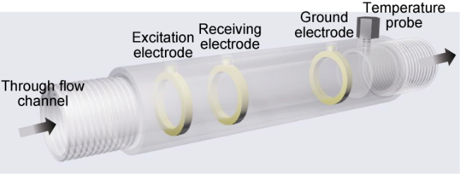
Fig. 1. Structure schematic of the conductance water cut sensor. |
1.2. Failure mechanism
During the service of the sensor, well fluid erosion, electrochemical corrosion and oil contamination are the three main factors that cause the failure of conductance water cut sensor, which will lead to electrode erosion, corrosion and oil adhesion, resulting in the gradual reduction of sensor measurement accuracy and stability, and finally leading to failure (Fig. 2 ).
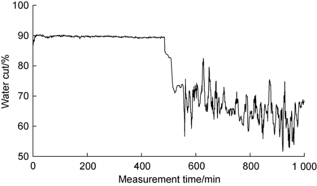
Fig. 2. Variation of measured water cut value over measurement time. |
(1) Well liquid erosion causes electrode wear and reduces the measurement accuracy. The Invar alloy material used for the electrode contains a large amount of austenitic structure, which has low hardness and poor wear resistance [15]. During working downhole, flowing well fluids constantly scour the surface of Invar alloy electrode, which gradually leads to the loss of surface material. For sand-producing wells, the well fluids contain a large number of fine solid particles, which constantly impinge and erode the electrode surface. The well liquids and solid particles will cause micro-pits and damage on the electrode surface, and the morphology of the electrode surface will change after a long time of service, which will reduce the measurement accuracy or even cause complete failure.
(2) The well liquids induce electrochemical corrosion of the electrode, resulting in the drift of the measurement results. The well fluids contain Cl−, SO42− and CO32− ions. When the sensor works in the downhole, ions exchange occurs between the electrode surface and the corrosive medium, resulting in electrochemical corrosion. The micro-cracks on the electrode surface due to erosion are corrosion microzones, which will aggravate the electrochemical corrosion process and form corrosion pits. Under the action for a long time, the austenite phase with poor stability in the etched pit will corrode continuously, which may extend the etched pit depth until perforation. After the electrode is corroded, the internal structure is destroyed and the resistivity distribution is not uniform, which increases the difference between the measured value and the real value, and finally causes the detection result to drift.
(3) Oil contamination adheres to the electrode surface, blocks the electrode conductivity, and directly causes failure. The formation fluids have high viscous resistance and low surface energy. When the produced fluids flow through the electrodes, crude oil or other medium are easy to adhere to the electrode surface. Especially when the electrode is worn and electrochemically corroded, the macro scratches or etched pits on the surface are more likely to aggravate the adhesion. An insulating layer of oil contamination is formed on the surface of the electrode to block the electrical signal between the electrodes and the well fluids, resulting in distortion and failure of the measurement results.
In conclusion, the combined effects of well fluid particles erosion, electrochemical corrosion and oil pollution are the main factors leading to the decrease of measurement accuracy and stability of conductance water cut sensor. In order to improve the wear resistance, oleophobic property and electrochemical corrosion resistance of Invar alloy electrode, it is necessary to modify the film to avoid sensor failure.
1.3. Ways of electrode surface modification
BDD film has excellent anti-friction and anti-wear properties, electrical conductivity and physicochemical stability, which is an ideal material to improve the service performance of Invar alloy electrode [16]. Electrode surface modification by using BDD film should meet the following three requirements.
(1) BDD film should have a low friction coefficient to overcome the erosion from well fluid. If the friction coefficient of BDD film is lower than 0.2, the modified electrode has self-lubricating property [17]. When the electrode with low friction coefficient and self-lubricating property collides with solid particles in the fluid, the friction and wear of solid particles on the electrode surface can be effectively reduced, and the wear resistance of the electrode can be improved. The surface roughness can reflect the friction coefficient and wear rate of the solid surface[18]. When the surface roughness is low, the mechanical locking effect between the convex body on the surface of the film and the solid particles in the well fluid is weak, so the friction coefficient and wear rate are low. More graphite particles in the film structure reduce the hardness of the film, so the film can be scratched easily by hard particles, thus leading to more serious wear on the film surface [19]. If the film has a high content of diamond phase, this phenomenon can be avoided, because it can effectively reduce the erosion of solid-liquid working medium on the electrode surface and improve the stability. Therefore, reducing the film roughness and increasing the diamond phase content of the film are necessary strategies to reduce the friction coefficient and improve the wear resistance. In this paper, the grain size, surface roughness and diamond phase content of the film were regulated by adjusting boron doping concentration, and the modified electrode with high wear resistance was constructed.
(2) BDD film should have higher electrochemical impedance modulus to improve the electrochemical corrosion resistance of the electrode. The electrochemical impedance modulus value can reflect the difficulty of electrochemical corrosion of electrode materials [20]. When the electrochemical impedance modulus of the electrode is high, the Invar alloy is not prone to corrosion. When the BDD film is deposited on the electrode surface as a protective layer and the low-frequency (0.01 Hz) impedance modulus of the film is higher than 1×10⁴ Ω•cm2, the coating has fewer defects and better corrosion resistance, which can effectively improve the electrochemical corrosion resistance of the electrode [21-22]. Deposition of dense BDD film with high impedance modulus on the surface of Invar alloy electrode is a key method to improve corrosion resistance. In this paper, the modified electrode with high electrochemical impedance modulus was prepared by optimizing the boron doping concentration and film deposition time to improve the surface compactness of the film.
(3) The surface of BDD film electrode should be oleophobic to avoid oil adhesion to the electrode. The micro/nano sized microstructure and surface chemical composition of the surface are the key to control the oleophobic surface of the electrode [23]. The surface of BDD film without modification treatment is oleophilic, so it is necessary to modify the surface chemical composition of micro/nano microstructure film to realize the oleophobic film. The contact angle can quantitatively reflect the wettability of the electrode surface. When the oil contact angle is greater than 90°, it indicates that the electrode surface is oleophobic, and the oil is not easy to wet the electrode. In this paper, the microstructure of BDD film was adjusted by adjusting the deposition time of the film, the micro and nano microstructure was constructed, and the BDD film was modified with fluorinated agent to reduce the surface energy and improve the oleophobic property of BDD film. The oleophobic film with oil contact angle greater than 90° was prepared.
2. BDD modified electrode preparation and tests
In view of the requirements of electrode surface modification, the deposition time and boron doping concentration of the film were regulated comprehensively, and microstructure and chemical state of the modified surface were coordinated together with fluoride modification treatment. Wear resistance, electrochemical corrosion resistance and oleophobic performance of the electrode may be thus improved to avoid early failure of the electrode and to extend the downhole service life.
2.1. BDD film preparation
BDD films were deposited in system of HFCVD (hot- filament chemical vapor deposition), and the preparation process was divided into two procedures of substrate pretreatment and deposition. Subsequently, several BDD films were chosen for fluorinated surface treatment according to the performance test results.
The substrate pretreatment had three steps. (1) The substrate of Invar alloy was placed in a mixture of acetone and absolute ethanol for 10 min to remove oil stains thereon by ultrasonic cleaning. (2) The cleaned substrate was blown dry with nitrogen and put into diamond seed crystal liquid (mixed liquid of 2 g diamond micro powder and 100 mL absolute ethanol) for 10 min of ultrasonic seed crystal. (3) After seeding, the substrate was ultrasonically cleaned in absolute ethanol for 2 min to remove excess diamond micro-powder, and then was blown dry for later use.
Deposition procedure. The treated substrate of invar alloy was set into reactor of HFCVD, and boron was doped into diamond film by means of the bubbling method. Specifically, ethyl alcohol solution with dissolved trimethyl borate was introduced to the reaction chamber using hydrogen; the reaction chamber was heated by tungsten filament, flow rate of hydrogen was set to 1025 mL/min, flow of ethanol is set to 50 mL/min; deposition pressure was 3 kPa and the deposition temperature was 800 oC. Doped boron concentration was controlled by adjusting ratio of trimethyl borate and ethanol. The boron concentration was expressed by ratio of boron and carbon atoms in mixed solution of trimethyl borate and ethanol. The boron doping concentration was set as 3×10⁻³, 6×10⁻³, 9×10⁻³ and 12×10-3, and four BDD films were then prepared. Subsequently, the deposition time was optimized at the optimal doping concentration to regulate the film microstructure, and the deposition time was set as 4, 6, 8 and 10 h.
The modified BDD samples with the best deposition time were fluorinated with perfluoro octane trimethyl silane to reduce the surface energy and to further improve the anti-oil adhesion ability of the modified electrode. The mixture of perfluoro octane trimethyl silane (5 mL) and ethanol (95 mL) was used as the modifier, in which the sample was soaked for 2 h to fulfill the fluorination treatment.
2.2. BDD film performance test
2.2.1. Test of erosion wear resistance
Microscopic morphology, carbon-valence bond structure, tribological performances and electrical conductivity of BDD films were detected using scanning electron microscopy, Raman spectrometer, reciprocating friction and wear tester and resistance tester, respectively. The erosion resistance was evaluated with simulated well fluid, whose compositions included water (80% mass fraction), crude oil (15% mass fraction), sodium chloride (0.5% mass fraction) and debris (4.5% mass fraction). For grinding ball, Si3N4 ceramic ball with diameter of 6 mm was selected, the load was set as 10 N, and the reciprocating frequency was 15 Hz. The measured value was the average of 5 times measurement of each sample.
2.2.2. Test of electrochemical corrosion resistance
Improvement effect of surface modification on electrochemical corrosion resistance of the electrode was investigated using BDD films prepared under the optimized process parameters (optimal erosion wear sample parameters). BDD films and pure Invar alloys were selected for comparative study under five natural aging times (1 week, 2 weeks, 1 month, 2 months, 4 months). 3.5% NaCl solution was used as corrosion electrolyte for electrochemical impedance measurement to investigate the difference of electrochemical corrosion behaviors before and after the modification. The scanning frequency ranged from 1×10⁻² Hz to 1×10⁵ Hz, and the amplitude was 10 mV. Nyquist curves and Bode impedance curves obtained in electrochemical impedance spectroscopy (EIS) test of Invar alloy and BDD film were compared to measure electrochemical corrosion resistance and durability of the film.
2.2.3. Test of oleophobic performance
The effects of deposition time on the microstructure of BDD films and the oil repellent performances of modified samples were analyzed, and 4, 6, 8, and 10 h were selected as research parameters. Oil contact angles of the samples before and after the film modification were measured by a contact Angle measuring instrument, where the oil viscosity was about 8 mPa·s, and the average value at five random sites was taken as the measured value.
3. Results and discussion
3.1. Test and analysis of erosion resistance performance
3.1.1. Microscopic morphology
Comparative observation of surface morphologies of BDD films with four boron doping concentrations (Fig. 3 ) indicates that the films are continuous and compact, the grain edges and angles are clear, and the grain size decreases firstly and then increases with the increase of boron doping concentration. When the boron doping concentration is 3×10⁻³, the average grain size is about 0.8 µm, and the construction of nano-sized grains is initially realized. Most of the grains on the surface of the film are sharp four-pyramid shaped. This is a typical structural feature of the (111) crystal plane of diamond, indicating that the film grows preferentially along the (111) crystal direction (Fig. 3 a). When boron doping concentration increases to 6×10⁻³, some flat rhomboid grains appear on the film surface, which corresponds to the (220) crystal plane of diamond. The grain size decreases to 0.6 µm, and the micro-nano structure of the film is well realized (Fig. 3 b). When the boron doping concentration increases to 9×10⁻³, the grain morphology on the film surface changes to rhomboid, indicating that the film preferentially grows along the (220) crystal direction. Meanwhile, the average grain size increases to 1 µm, the surface roughness of the film increases, and the micro-nano structures are destroyed (Fig. 3 c). When boron doping concentration further increases to 12×10-3, the overall grain surface morphology is still rhombus, and the average grain size is still 1 µm. However, occurrence of some secondary grains increases the surface undulation further (Fig. 3 d).
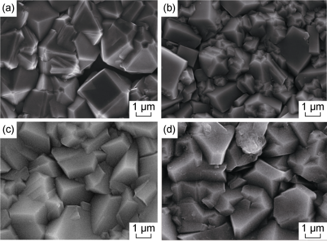
Fig. 3. SEM images of BDD films with four boron-doping concentrations. (a) A boron-doping concentration of 3×10⁻³; (b) A boron-doping concentration of 6×10⁻³; (c) A boron- doping concentration of 9×10⁻³; (d) A boron-doping concentration of 12×10-3. |
The change of BDD grain morphology is attributed to the effect of boron doping on diamond nucleation and growth [24]. During the film deposition, boron element is doped by combining with the dissociated -CHN group (n is the number of H atoms). When the boron-doping concentration is too low, B-ChN groups preferentially nucleate and grow along the (111) crystal plane to form the preferred orientation due to the high lattice matching with the substrate, and the higher nucleation density induces the formation of nanocrystalline morphology. With the increase of boron doping concentration, the nucleation of (111) crystal plane is inhibited, the nucleation density of (220) crystal plane increases, and the two grains grow competitively. Consequently, the grain size is refined, and the preferred orientation of (111) crystal plane is then destroyed. Excessive boron doping concentration directly leads to the preferential nucleation and growth of (220) crystal plane, and brings the increase of grain size, the prominent preference orientation of (220), and the increase of film surface fluctuation. In this case, the diamond grains in (111) crystal direction contain more boron exposure sites, which is more conducive to realize good conductive performance [25]. Meanwhile, small grain size gives the film low surface roughness and good micro-nano structure. As a result, BDD film with boron doping concentration of 6×10⁻³ has the smallest grain size (0.6 µm) and more (111) grain plane grains, showing good nanoscale microstructure.
3.1.2. Carbon valence bond structure
Films prepared at two typical boron doping concentrations of 6×10⁻³ and 12×10-3 were selected to compare carbon valence bond structures of BDD films (Fig. 4 ). Raman spectroscopy is a common-used method to characterize valence bond structure of carbon. Wave number of characteristic peaks in Raman spectrum represents types of valence bond structures, and the intensity reflects valence bond content. When boron doping concentration is 12× 10-3, a sharp characteristic peak (D peak) occurs at 1332 cm-1 and corresponds to diamond phase of sp3 hybridization; a strong characteristic peak (G peak) can also be observed near 1580 cm-1, which belongs to amorphous carbon phase formed by sp2 hybridization. Intensity ratio of D peak to G peak (ID/IG) reflects phase formation quality and impurity phase content of film. The calculated value of ID/IG is 1.25, indicating that amorphous carbon content of the film is high at this boron doping concentration, and the phase formation quality deteriorates. When boron doping concentration is 6×10⁻³, two characteristic peaks (D and G) can still be observed, but the difference is that the full width at half maximum (FWHM) of G peak increases and its intensity decreases greatly, while D peak becomes narrow, and ID/IG value is 4.47. In this case, diamond content of BDD film increases, impurity phase content decreases, and phase formation quality is improved.
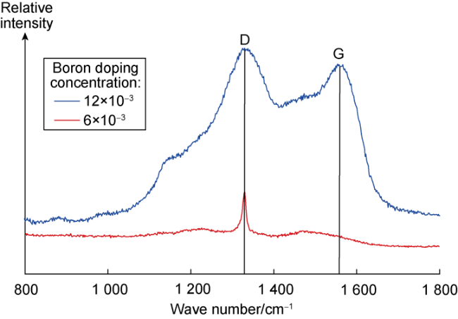
Fig. 4. Raman spectra of BDD films prepared at two boron doping concentrations. |
Due to doping effect of boron element on diamond lattice, a high doping amount may result in a poor phase quality and an increase of impurity. Trace boron element doping can replace carbon atoms in diamond lattice, but excessive boron element doping may form compounds with hydrocarbon groups and exist in form of amorphous carbon. Hardness and wear resistance of amorphous carbon are much lower than that of diamond, and amorphous carbon as an impurity phase can weaken tribological performances of BDD films [26]. BDD films prepared at a boron doping concentration of 6×10⁻³ exhibit good phase quality and low impurity content. This is more conducive to obtain good tribological performance to cope with erosion and wear of electrodes.
3.1.3. Tribological performance
Comparison of average frictional coefficient in steady- state condition between Invar alloy, boron undoped diamond film and four BDD films (Fig. 5 a) shows that film modification reduces frictional coefficient of Invar alloy greatly and adjusting boron doping concentration can further optimize tribological performance of the film. Before modification, friction coefficient of Invar alloy is as high as 0.62, and after modification, it lowers to 0.4 for a good wear resistance. Under action of boron doped, friction coefficient of modified sample initially decreases and then increases. The lowest friction coefficient is only 0.05 and belongs to the sample with boron doping concentration of 6×10⁻³. It is noteworthy that friction coefficient values of BDD films with four boron concentrations are uniformly less than 0.2, and such good self-lubricating effect can meet the modification requirements.
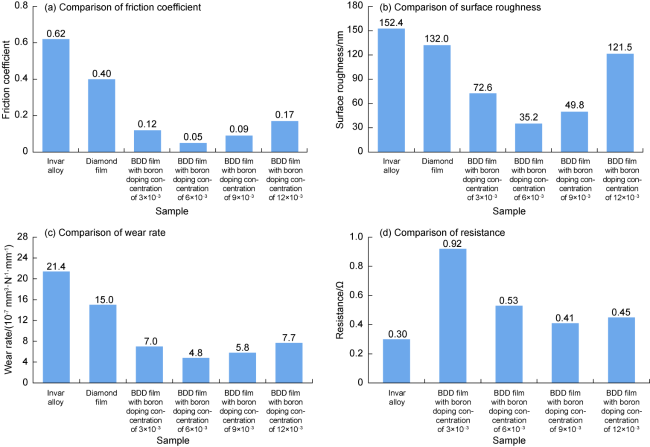
Fig. 5. Performances comparison of Invar alloy, boron undoped diamond film and four BDD films. |
Due to grain refinement and preferred orientation caused by boron doping, variations of surface roughness and wear rate of the films are consistent with that of friction coefficient. Diamond film without boron doped has larger surface roughness and wear rate, which are 132 nm and 15×10-7 mm3/(N•mm) respectively. With increase of boron doping concentration, both surface roughness and wear rate have a trend of decreasing firstly and then increasing. Modified samples with boron doping concentration of 6×10⁻³ have the lowest surface roughness and wear rate of 35.2 nm and 4.8×10⁻⁷ mm3/(N•mm), respectively (Fig. 5 b, 5c). The results indicate that BDD film with boron doping concentration of 6×10⁻³ has optimal tribological performance and can deal with wear failure of electrodes from well fluid erosion.
3.1.4. Electrical conductivity
Resistance values of modified samples of BDD films are measured to evaluate effect of modification on electrical conductivity (Fig. 5 d). Resistance values of modified sample are slightly higher than that of Invar alloy. With increase of boron doping concentration, number of holes and impurity phase content of BDD films increase, and the resistance decreases. In brief, modified BDD film samples have similar resistance values to that of Invar alloy. This confirms that the modification of BDD film cannot damage conductivity of electrode, so it has no impact on core functionality of measurement.
3.2. Test and analysis of electrochemical corrosion resistance
Electrochemical corrosion resistance of the electrode can be evaluated according to radius of real part of impedance curve of Nyquist curve. The larger the arc radius of the curve or the larger the slope of the Nyquist curve at low frequencies, the larger the impedance of the electrode, i.e., the better the electrochemical corrosion resistance [27]. A comparison of Nyquist curves between Invar alloy and BDD films under five natural aging conditions (Fig. 6 ) shows that radius of real impedance arc of Nyquist curves of BDD films is much higher than that of Invar alloy, and indicates that electrochemical corrosion resistance of BDD films is better than that of Invar alloy. Radii of Nyquist curves of BDD film decrease with increase of the aging time. As storage time increases, air oxidation of BDD film weakens electrochemical corrosion resistance of BDD films. Notably, the air oxidation does not damage the structure of BDD film seriously, and its curve radius is much higher than that of Invar alloy. This indicates that the modified electrode presents a stable and good electrochemical corrosion resistance.
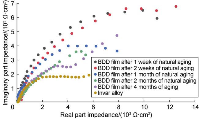
Fig. 6. Nyquist plots of Invar alloy and BDD films with five natural aging times. |
The electrochemical impedance modulus value corresponding to 0.01 Hz in the low-frequency region of Bode impedance curve represents the overall impedance of the sample. And the larger modulus means the better electrochemical corrosion resistance of the film [28]. The Bode impedance curves of Invar alloy and BDD film under five natural aging conditions (Fig. 7 ) show that electrochemical impedance modulus of Invar alloy is 118.6 Ω•cm2, and the impedance modulus of BDD film under five natural aging conditions (1 week, 2 weeks, 1 month, 2 months, 4 months) are 1.68×10⁴, 1.63×10⁴, 1.85×10⁴, 0.82× 10⁴, 0.58×10⁴ Ω•cm2, respectively. Electrochemical impedance modulus of BDD film is higher than 1×10⁴ Ω•cm2 when the natural aging is 1 week, 2 weeks and 1 month. Electrochemical impedance modulus of BDD film is slightly lower than 1×10⁴ Ω•cm2 after 2 and 4 months of natural aging, but it was still much higher than that of the sample before modification. Bode impedance curves also confirm good electrochemical corrosion resistance and durability of BDD films. Together with results of Nyquist curves, it is shown that the modification of BDD film can improve electrochemical corrosion resistance of the conductance sensor electrode, and ensure its good electrochemical stability in the downhole environment.
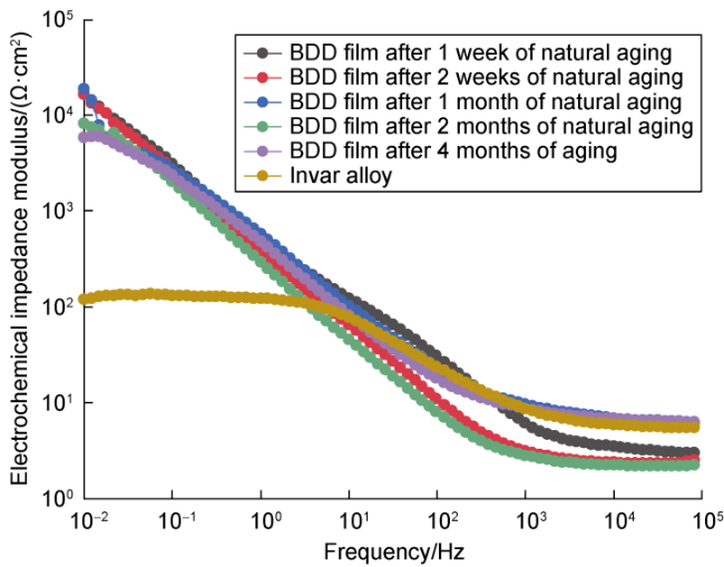
Fig. 7. Bode plots of Invar alloy and BDD films with five natural aging times. |
The modification of BDD film effectively improves electrochemical corrosion resistance of sensor electrodes attributed to three factors: (1) BDD films block the propagation path of corrosive media, avoiding direct contact between electrodes and corrosive media; (2) the electrochemical stability of BDD films can resist erosive effect of corrosive media; (3) BDD film has good erosion resistance, avoiding sprouting of corrosion cracks and pits.
3.3. Test and analysis of oleophobic performance
Comparative observation of surface morphologies of BDD films at different deposition times (Fig. 8 ) indicates that the average grain size gradually increases, and homogeneity of the films initially improves and then deteriorates with increase of the deposition time. At deposition time of 4 h (Fig. 8 a), the average grain size is small, the grain size difference is large, and the film compactness and surface homogeneity are poor. At the deposition time of 6 h (Fig. 8 b), compactness and average grain size of the film increases, but the grain size difference is not improved because of preferred orientation absence. At the deposition time of 8 h (Fig. 8 ), the grain size continues to increase, but still but still exhibits nanocrystalline morphology; a majority of the grains are in shape of sharp quadrilateral pyramid, and present a preferred orientation; the grain size and distribution on the film surfaces are uniforms, and film has good homogeneity. At the deposition time of 10 h (Fig. 8 d), the average grain size is too large, the surface fluctuation increases, and the film homogeneity becomes worse.
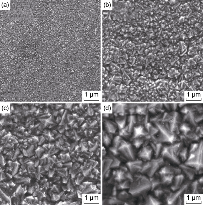
Fig. 8. Morphologies of BDD films prepared with four deposition times. (a) 4 h of deposition; (b) 6 h of deposition; (c) 8 h of deposition; (d) 10 h of deposition. |
The change in microstructure of films is attributed to the joint action of two factors. (1) With increase of the deposition time, the continuous input of external heat source and carbon source promotes nucleation and growth of the grain. (2) Grains growth is inhibited as the grain boundary energy of grown BDD grains decreases with increase of the deposition time. Synergistic effect of the two factors may form BDD film with homogeneous nanocrystalline. The grains of BDD film prepared at 8 h are small and evenly distributed. This good micro-nano structure is the most conducive to improve the oleophobic performance of the modified electrode.
Comparison of oil contact angle test results between Invar alloy and four BDD films at different deposition times (Fig. 9 ) indicates that BDD film modification effectively improves oleophobic performance of the samples. Invar alloy shows strong lipophilicity with the minimum contact angle (26.58°). Invar alloy is mainly composed of Fe (64%) and Ni (36%) and high surface energy results from strong non-polar metal bonds between the atoms[29], so oil can readily spread on the surface of Invar alloy. Different from Invar alloy, BDD film has a low surface energy, so the spreading ability of oil on the film surface is decreased and the oleophobic performance is improved. With increase of the deposition time, the homogenization of BDD film improves, the surface roughness increases, and the contribution of micro/nano structure to oleophobic performance increases gradually. Specifically, oil contact angle of BDD film with the deposition time of 8 h is 56.70°, which is more than twice that of Invar alloy. This indicates that controlling the deposition time can effectively improve oleophobic performance of BDD films, so as to improve resistance of the modified electrode to oil pollution and adhesion. At deposition time of 10 h, oil contact angle of BDD film decreases to 49.41° as the film grain size continues to increase.
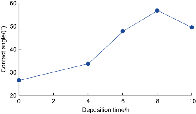
Fig. 9. Contact angles of Invar alloy (deposition time of zero) and BDD films with different deposition times. |
SEM images of fluorinated BDD films at different magnifications (Fig. 10 a, 10b) exhibit that the grain morphology does not have visible change in majority, but the grain surface is attached with gray membrane- like material, which is a new nanoscale protrusion. This is attributed to interaction between fluorinated agent and diamond functional groups, along with self- assembly process. The occurrence of nanoscale protrusion and introduction of fluorinated agent jointly lower surface energy of the film and improve the oleophobic capacity. Oil contact angle of fluorinated sample reaches 97.5°, and presents a good oleophobic effect (Fig. 10 c). This result provides direct evidence that the modification of BDD film can improve the resistance of electrode to oil pollution and adhesion.
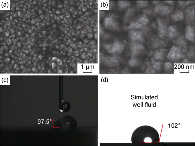
Fig. 10. Effect of fluorination treatment on wettability of BDD films. (a) SEM image at 5000 magnifications; (b) SEM image at 20 000 magnifications; (c) Contact angle of fluorinated samples; (d) Contact angle in simulated well fluid environment. |
Downhole crude oil is used to test oil contact angle of the modified electrode in the simulated well fluid environment, so as to further evaluate oleophobic performance of the modified electrode. Crude oil is mixed with water in volume ratio of 1:1 and heated to 60 °C as simulated well fluid and placed in a glass tank. The modified film sample is immersed in the simulated well fluid, and the crude oil is sucked into a syringe. U-shaped needle is used to drop crude oil onto the sample surface, and the result calibration is completed by rotating 180° counterclockwise after the photo collection, as shown in Fig. 10 d. Crude-oil contact angle of the modified sample is as high as 102°, which is about 4 times that of Invar alloy. This test result verifies that the film modification makes the sample present a superior oleophobic performance.
4. Simulation of engineering test and sensor package
To evaluate the engineering applicability of the BDD modified film strategy, performance tests were conducted to simulate actual operating conditions. The modified electrodes were investigated from the aspects of erosion resistance, electrochemical corrosion and oil adhesion in turn, and the encapsulation process of the sensors was optimized to ensure the integrity of the electrode surface films. The results were analyzed and evaluated by conducting validation experiments under simulated conditions.
4.1. Erosion resistance
The object of the simulated working condition was the oil production well with high water cut and large sand production. The experimental conditions were set as follows: prepare 500 mL of crude oil and water mixture with a volume ratio of 1:10 as well fluid, select 50 g of quartz sand with an average particle size of 3 mm as the friction pair of the electrode element. The mixed fluid was stirred at a speed of 100 r/min to simulate the flow of the well fluid, and the electrodes were placed in the above mixed system for accelerated experiments. After 24 h, the electrode elements were removed and ultrasonically cleaned with acetone solution. After being blown dry with nitrogen, the macroscopic morphology of the surface was observed. In addition, the electrode elements before and after modification were tested by using friction and wear testing machine to obtain the tribological performance index.
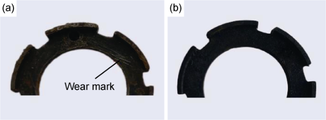
Fig. 11. Macroscopic erosion morphologies of electrode components (a) before and (b) after modification. |
4.2. Electrochemical corrosion resistance
Corrosive medium solution was prepared to conduct electrochemical corrosion experiments on the electrode elements before and after modification. The experimental temperature was 60 °C, the pH of the corrosive medium solution was 6.9, and the ion composition was Cl- (mass concentration 3619.5 mg/L), CO32- (mass concentration 673.5 mg/L), HCO3- (mass concentration 1604.8 mg/L) and SO42- (mass concentration less than 5 mg/L). The electrode elements before and after modification were submerged in the simulated well fluid by applying a potential value of +0.5 V. The mixture was stirred with a magnetic mixer at 100 r/min to simulate the well fluid flow for accelerated experiments. And after 1 h, the electrode was taken out to observe its surface morphology.
There were obvious rust stains and irregular pits on the surface of the electrode before the modification (Fig. 12 a). There were a few rust stains on the surface of the modified electrode, but no obvious pits appeared (Fig. 12 b). In order to further observe the corrosion morphology on the surface of the electrode element before and after modification, SEM was used to observe the microscopic morphology of the corrosion area. A large number of corrosion pits with diameters of 1-10 µm and a small number of corrosion microcracks with lengths of 3-25 µm appeared on the surface of the electrode before the modification (Fig. 12 c). Most of the BDD grains were well preserved, and a few of them were attached with particles with a diameter of about 100-500 nm (Fig. 12 d), which were the BDD grains damaged by corrosion, and their macroscopic appearance was the rust stains shown in Fig. 12 b. It is confirmed that the modified electrode has excellent electrochemical corrosion resistance, and the electrode has not undergone significant electrochemical corrosion in the accelerated corrosion experiment and can withstand the electrochemical corrosion of the well fluid environment.
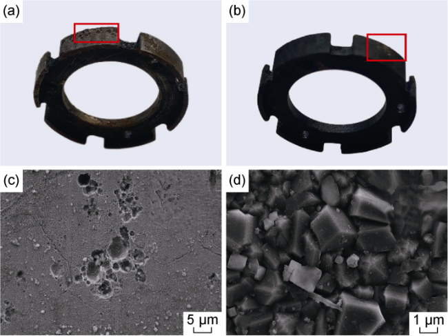
Fig. 12. Surface corrosion morphologies of electrode components. (a) Macroscopic corrosion morphology of uncoated electrode; (b) Macroscopic corrosion morphology of coated electrode; (c) Microscopic corrosion morphology of uncoated electrode; (d) Microscopic corrosion morphology of coated electrode. |
4.3. Oleophobic performance
The oleophobic performance of BDD films was evaluated jointly in terms of both time stability and temperature stability. The change graph of oil contact angle of BDD film in air environment over time shows (Fig. 13 a) that under the condition of air temperature 25 °C and the maximum exposure time 15 d, the oil contact angle of the film always remains around 90° without substantial decay with the extension of time. The modified samples were placed in a two-phase mixture of crude oil and water (1:3 by volume), which was heated to 50 °C to simulate a well fluid environment and stirred at high speed to simulate well fluid flow. With the extension of time, only a slight decay in the contact angle of the sample crude oil occurred (Fig. 13 b). Tests in both environments show stable film surface states and surface properties with long-lasting oleophobic performance.
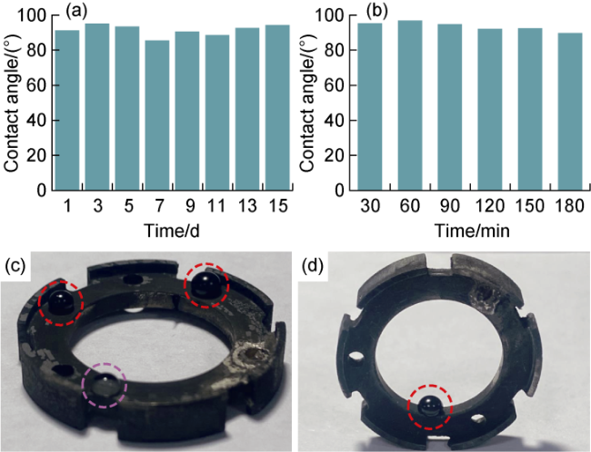
Fig. 13. Assessment of anti-oil adhesion stability of BDD film modified electrodes. (a) Oil contact angle in air; (b) Crude oil contact angle in well fluid; (c) Oil spreading on electrode surface, red circle shows the pattern of crude oil on treated electrode surface, and purple circle shows the pattern of two-phase mixture of crude oil and water on treated electrode surface; (d) Oil spreading on the inner wall of the electrode, red circle shows the pattern of crude oil on treated electrode surface. |
The oleophobic performance of the BDD film modified electrode was verified (Fig. 13 c, 13d). The red circles show the morphology of crude oil on the surface of the modified electrode, and the purple circles show the morphology of the two-phase mixture of crude oil and water on the surface of the modified electrode. It can be seen that neither crude oil nor oil-water mixture spreads on the surface of the modified electrode, but in the form of liquid droplets, which visually demonstrates the good oleophobic performance of the modified electrode. Likewise, the crude oil exhibits good oleophobic performance on the inner wall of the modified electrode.
In summary, the BDD film-modified electrode element exhibits good resistance to erosion and wear, electrochemical corrosion resistance and oleophobic performance in the simulated working condition test, and has the ability to adapt to the downhole measurement environment for a long time.
4.4. Sensor package
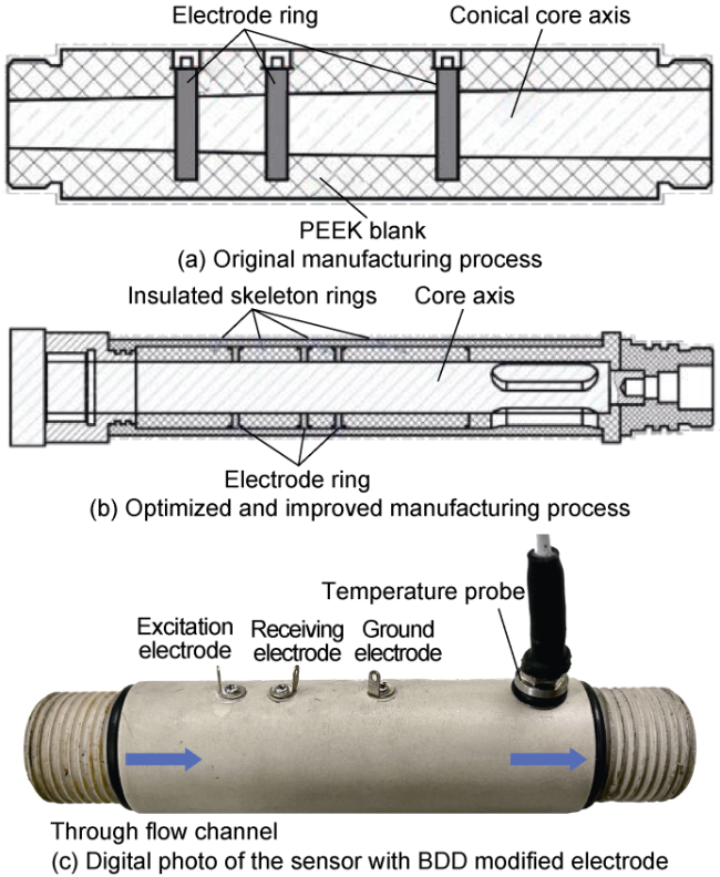
In order to guarantee the measurement accuracy and long-term reliability of the water cut sensor in the complex environment of the well, an integrated structure and encapsulation process is used, with three electrode rings and wires integrally molded into the sensor tube wall.
In the original manufacturing process, a tapered die steel is used as the mandrel, on which an annular positioning step is machined from large to small according to the designed electrode spacing to fix the electrode ring, and the electrode ring with the same outer diameter and gap fit with the positioning step is set into the mandrel and fixed to the outer die (Fig. 14 a). PEEK (polyether ether ketone) material is injected at 380 °C and 130 MPa, and after the workpiece cools down, the workpiece arbor is partially hollowed out using a boring tool to expose the inner surface of the electrode ring inside the workpiece to complete the internal machining. In this manufacturing process, the electrode surface forming is done by boring in the last process, and the BDD film preparation process cannot be implemented in the deeper position of the tube inner wall.
Fig. 14. Comparison of the packaging processes for water cut sensor and its digital photo. |
The encapsulation process was optimized and improved in order to guarantee the integrity of the surface of the BDD film-modified electrode. The optimized injection mold is a 3-layer structure, including the mandrel, skeleton and outer mold (Fig. 14 b). The mandrel is a cylindrical mold steel, designed with a positioning structure to install the skeleton ring of non-metallic insulating material and the modified electrode ring in precise series according to the design dimensions. The coupling agent is painted between the skeleton ring and the electrode ring to play a leak-proof sealing role, and the positioning structure of the skeleton is installed with the outer mold positioning. After that, injection molding is carried out also at 380 °C and 130 MPa. The electrodes are mounted and injected with support material. After the temperature is cooled down, the mandrel is withdrawn using tooling and then annealed. The fabrication of a prototype sensor was completed using this process (Fig. 14 c). Practice shows that the encapsulation process can guarantee both the tight bonding of the sensor electrode and the support structure during the injection molding process and the integrity of the sensor sensitive electrode surface structure.
5. Conclusions
Well liquid erosion, electrochemical corrosion and oil contamination are easy to cause wear, corrosion and scaling of conductance moisture sensor electrodes, leading to early electrode failure. Surface modification technology of BDD film is used to treat the electrode surface, and the wear resistance, electrochemical corrosion resistance and oleophobic performance of the electrode are improved in a combination of fluoride treatment and regulation of boron doping concentration and deposition time. The surface microstructure of the film can be improved by adjusting the boron doping concentration. When boron concentration is 6×10⁻³, the high wear resistance and electrochemical corrosion resistance of the film give the modified electrode good erosion resistance and corrosion resistance. The deposited grains of BDD films prepared at 8 h are small and evenly distributed, and exhibit a good micro-nano structure, which is most conducive to improve the oleophobic performance of the modified electrode.
The application of BDD film modified electrode in simulated working conditions indicates that the modified electrode has superior performance to resist erosion wear, electrochemical corrosion and oil adhesion. The encapsulation test results of the sensor prototype indicate that the optimized encapsulation process ensures the tight bonding of the modified electrode and the support structure, as well as the integrity of the electrode surface structure.
The BDD film surface treatment technology is expected to ensure the long-term stability of conductance moisture sensor in complex working conditions of oil wells. Moreover, the technology can also be applied to surface modification of other downhole sensors to ensure long-term accurate measurement of downhole sensing technologies and devices.