

Introduction
The in-fracture temporary plugging and diverting hydraulic fracturing (ITPDF) technology is an important means to develop shale gas reservoir and tight sandstone gas reservoir [1-2]. The temporary plugging agent is transported to the inside of the fracture through the fracturing fluid to form the plugging layer. When the plugging layer is formed at the fracture inlet, the unopened cluster can be opened to complete the turning between clusters. When the plugging layer is formed at the fracture tip, excessive extension of fracture is prevented, the risk of inter-well frac-hit is reduced, and the net flow pressure between the plugging layer and the fracture inlet is increased to create new fractures, thereby increasing the complexity of the fractures. After construction, as the temperature of the fluid inside the fracture increases, the temporary plugging agent gradually dissolves and then flows back to the ground with the fracturing fluid [3-4]. Due to the unclear understanding of the plugging behavior characteristics of the temporary plugging agent in hydraulic fracture, there is a lack of theoretical support for the selection of construction parameters such as the quantity, adding time and concentration of the temporary plugging agent, and the displacement and viscosity of the carrying fluid for ITPDF.
In the field of hydraulic fracturing, in view of the research on the plugging behavior characteristics of temporary plugging agents in fractures, non-visual horizontal fracture is used mostly to study the effects of temporary plugging agent size and concentration, carrier fluid viscosity and displacement, fracture width and surface morphology and other factors on the formation conditions of plugging layer [5⇓⇓⇓⇓⇓-11], or based on non-visual temporary plugging devices to evaluate the plugging and pressure bearing capacity of temporary plugging agents[12⇓-14]. However, the process of forming the plugging layer in the hydraulic fracture is rarely involved. Moreover, the hydraulic fracture is horizontal, so the influence of gravity on the plugging behavior characteristics of the temporary plugging agent in the hydraulic fracture cannot be considered. In the field of drilling fluid leak prevention and plugging, non-visual experimental device is also used to optimize the formula of temporary plugging agents with the goal of maximizing the pressure bearing capacity of plugging layer [15⇓⇓-18].
At present, there are relatively few literatures on the use of visual experimental device to study the plugging behaviors of temporary plugging agents in hydraulic fracture, which mainly involve the process of fiber-forming plugging layer, and the conditions for fiber and particle forming a plugging layer at constant fluid displacement and viscosity [19⇓-21]. There are some temporary plugging visual experiments in the field of drilling fluid leak prevention and plugging [22-23]. For example, Li et al. [22] performed a visual experiment of temporary plugging and found that the bridging mode of temporary plugging particles in fracture is mainly affected by the concentration of temporary plugging particles; however, they did not analyze the process of forming a plugging layer in natural fracture. Thus, the main controlling factors, formation modes and characteristics of each stage of plugging layer formation by temporary plugging particles in hydraulic fractures have not been studied thoroughly.
In this paper, the temporary plugging agent transport and plugging visual experimental device and the common temporary plugging particles were used to investigate the formation process of plugging layer. The influences of carrier fluid displacement and viscosity, and temporary plugging particle size and concentration on the formation process of plugging layer in hydraulic fractures were analyzed, and the plugging behaviors of temporary plugging particles and the formation conditions of plugging layer were discussed. It is expected to provide technical support for the design of ITPDF in oilfields.
1. Temporary plugging experiment
1.1. Temporary plugging particles
In order to reduce the error of the experimental results caused by the heterogeneity of the shape and size distribution of temporary plugging particles, the temporary plugging particles with the diameter of 1.0-3.0 mm were screened, and those with the equivalent diameter of 1.8, 2.4 and 3.0 mm were obtained as the experimental samples (Fig. 1 ).
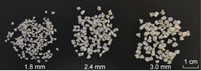
Fig. 1. Experimental samples. |
The density and shape of the temporary plugging particles are important factors affecting the plugging behaviors of the temporary plugging particles in hydraulic fractures [24]. Therefore, the true density of the temporary plugging particles was tested firstly, and then the shape characteristics of the temporary plugging particles were quantitatively described by ImageJ software (Table 1 ) [24]. It can be seen that the true density of temporary plugging particles is 1.12 g/cm3, and the shape characteristics of temporary plugging particles with different sizes are consistent; all of them are non-spherical particles, in which the aspect ratio is 1.38-1.41 and the roundness is 0.75-0.78.
Table 1. Density and shape characteristics of temporary plugging particles |
| Diameter/mm | True density/(g·cm−3) | Aspect ratio | Roundness |
|---|---|---|---|
| 1.8 | 1.12 | 1.38 | 0.78 |
| 2.4 | 1.41 | 0.78 | |
| 3.0 | 1.41 | 0.75 |
1.2. Experimental device
Through literature review, it is found that the experimental devices used for ITPDF are basically non-visual[5⇓⇓⇓⇓⇓⇓⇓⇓-14] and a small number of visual experimental devices are mainly used for drilling fluid leak prevention and plugging [22-23]. The visual experimental devices are deficient for: (1) The experimental displacement is small, and it is difficult to meet the similarity transformation between the field and indoor experimental displacements. (2) The pressure-bearing capacity of the visual fracture board is low, with the maximum of 0.4 MPa [22-23], and the pressure change cannot be recorded during the experiment. (3) The experimental object is natural fractures rather than hydraulic fractures, and the length, height and width of the visual fracture board are small, which cannot meet the requirements of ITPDF experiment. Therefore, the visual experimental device for temporary plugging in hydraulic fracture was developed in this paper (Fig. 2 ), which is mainly composed of seven parts: (1) Pump system, with the maximum displacement of 2 L/min and the maximum pumping pressure of 10 MPa. (2) Mix system, which is used to stir and mix carrier fluid and temporary plugging particles, with the maximum volume of 5 L and the maximum pressure of 15 MPa, which can prevent temporary plugging particles from settling in the container. (3) Record control system, which is used to record the pressure during the formation of the plugging layer once per second, with the highest accuracy of 0.001 MPa. (4) Pipeline system, with inner diameter of 14 mm and the length of 25 cm. (5) Visual fracture system, with the total length of the fracture of 50 cm, and the height is designed to be 10 cm based on the principle of minimizing the hydraulic radius error. In order to ensure the same experimental fracture width with the actual fracture width, the fracture width of the design device is adjustable in 0-10 mm, and the maximum pressure is 1 MPa. The fracture surface is rough, with the roughness set according to the roughness coefficient standard curve, and the roughness coefficient of 18-20. (6) Video acquisition system. Industrial camera is used to record the movement status of temporary plugging particles in hydraulic fractures in real time. (7) Fracturing fluid circulation system, for the separation of temporary plugging particles and fracturing fluid.
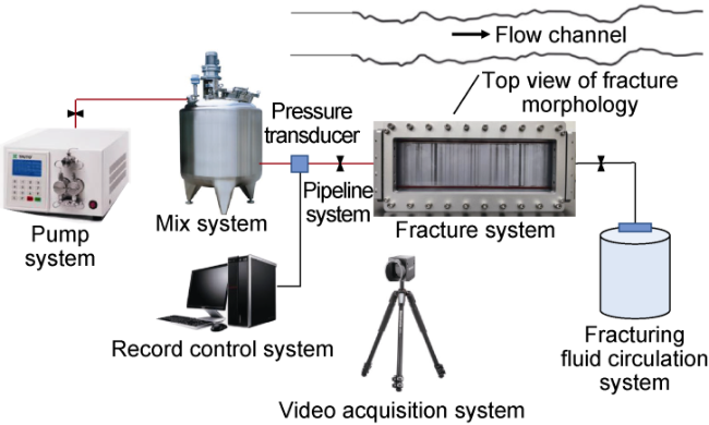
Fig. 2. Schematic diagram of experimental device. |
1.3. Experimental design
Scheme design: For shale reservoirs in Weiyuan block, Sichuan Basin, temporary plugging agents are pumped at a displacement of 3-6 m3/min, and there are a total of 7 clusters in one section. Assuming that only 4-5 clusters are opened at a time, the single cluster displacement is 0.60-1.50 m3/min, and thus the single-fracture displacement is 0.30-0.75 m3/min. It is assumed that the actual fracture height is 25 m and the width at fracture inlet is 8 mm, so the experimental fracture width is set to 4 mm [25]. The velocity similarity criterion is used to calculate the experimental displacement, the single-fracture displacement of 0.35, 0.65 and 0.80 m3/min are simulated with the corresponding experimental displacements of 0.7, 1.3 and 1.6 L/min, respectively. The carrier fluid with viscosity of 3-5 mPa·s is used to carry temporary plugging agent on site. In the experiment, the viscosity of the carrier fluid is set as 1, 3 and 6 mPa·s. The temporary particle concentration is set to 2.5, 5.0, 10.0, 15.0, 20.0 and 40.0 kg/m3. A total of 58 sets of experimental schemes are designed according to the combinations of the above parameters such as fracture width, carrier fluid displacement, carrier fluid viscosity, temporary plugging particle size and temporary plugging particle concentration, etc. (Table 2 ).
Table 2. Parameter combination of experiment scheme |
| Fracture width/mm | Temporary plugging particle size/mm | Ratio of particle size to fracture width | Temporary plugging particle mass concentration/(kg•m−3) | Carrier fluid viscosity/ (mPa•s) | Carrier fluid displacement/ (L•min−1) | Group of experiment |
|---|---|---|---|---|---|---|
| 4 | 1.8 | 0.45 | 10.0 | 3 | 0.7 | 1 |
| 15.0 | 3 | 0.7 | 1 | |||
| 20.0 | 1, 3, 6 | 0.7, 1.3, 1.6 | 9 | |||
| 40.0 | 1, 3, 6 | 0.7, 1.3, 1.6 | 9 | |||
| 2.4 | 0.60 | 5.0 | 3 | 0.7 | 1 | |
| 10.0 | 1, 3, 6 | 0.7, 1.3, 1.6 | 9 | |||
| 20.0 | 1, 3, 6 | 0.7, 1.3, 1.6 | 9 | |||
| 3.0 | 0.75 | 2.5 | 3 | 0.7 | 1 | |
| 5.0 | 1, 3, 6 | 0.7, 1.3, 1.6 | 9 | |||
| 10.0 | 1, 3, 6 | 0.7, 1.3, 1.6 | 9 |
Experiment steps: (1) Close the control valve between the systems, meanwhile, based on the parameters set in the experiment scheme, temporary plugging particles and carrier fluid are added into the mix system. (2) Open all valves, start the pump system, and set the experimental displacement according to the experiment scheme. (3) Record the experiment pressure and collect video in real time.
2. Plugging layer formation conditions
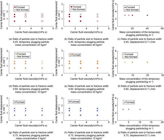
Fig. 3. Parameter combination for forming plugging layer by temporary plugging particles in hydraulic fracture. |
3. Plugging layer formation process
3.1. Formation stages
The variation data of plugging layer height, plugging layer length and pressure over time during the formation of plugging layer in all experiment were collected and averaged to obtain the trend curve (Fig. 4 ). According to whether the temporary plugging particles form a complete plugging layer in the direction of the fracture height (when the ratio of the plugging layer height to the fracture height is 100%, it is considered as a complete plugging), the formation process of the plugging layer can be divided into two stages: the height growth stage of the plugging layer and the length growth stage of the plugging layer. In the height growth stage of the plugging layer, the rear pressure of the plugging layer is 0 MPa. When the fracture height is blocked completely by temporary plugging particles, the rear pressure of the plugging layer starts to rise. In the length growth stage of the plugging layer, with the increase of the plugging layer length, the rear pressure of the plugging layer increases continuously. The change trends of length and pressure are consistent.
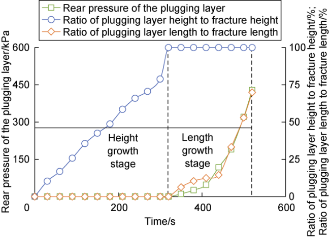
Fig. 4. The relationship of length, height and pressure of plugging layer with time. |
3.2. Formation modes
According to the statistical analysis of particle distribution pictures in 58 groups of experiment, the formation mode of the plugging layer can be divided into four categories. In Fig. 5 , the left side is the fracture inlet, and the right side is the fracture outlet. The positive direction of the fracture is from the inlet to the outlet; the part near the inlet is the rear, and the part near the outlet is the front. When the temporary plugging particles fill the fracture height completely, the accumulated layer is the plugging layer (red dotted line box). When the temporary plugging particles do not fill the fracture height completely, it is the accumulated layer (black dotted box).
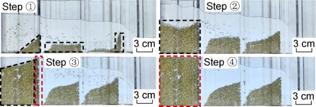
Fig. 5. Temporary plugging particle distribution during the formation of plugging layer (Mode I). |
The formation process of plugging layer in Mode I is divided into four steps (Fig. 5 ). Step ①: The temporary plugging particles accumulate at different positions at the bottom of the fracture. In the direction near the fracture inlet, a triangular accumulation layer is formed, which gradually rises along the positive direction of the fracture. Step ②: When the front of the triangle reaches a certain height, the accumulation rate of the temporary plugging particles in the rear is faster than that in the front, and the triangular accumulation layer is gradually transformed into a rectangular one. Step ③: At the rear of the accumulation layer, the temporary plugging particle accumulation rate gradually slows down; at the front of the accumulation layer, the accumulation rate gradually speeds up. At the front of the rectangular accumulation layer, the particles accumulate continuously until the fracture height is filled. The plugging layer is formed at the front of the accumulation layer firstly, and the plugging layer is short. Step ④: Temporary plugging particles continue to accumulate above the accumulation layer between the plugging layer and the fracture inlet, and fill the fracture gradually. The length of the plugging layer increases until the fracture is filled completely. The temporary plugging particles entering the fracture to Step ③ is the height growth stage of the plugging layer, and Step ③ to Step ④ is the length growth stage of the plugging layer.
The combination of formation parameters of plugging mode I includes (Table 3 ): the ratio of particle size to fracture width is 0.45 or 0.60, the carrier fluid viscosity is 1 mPa·s, which is independent of the carrier fluid displacement and particle mass concentration. Thus, the controlling factors for Mode I are the ratio of particle size to fracture width and the carrier fluid viscosity. Because the ratio of particle size to fracture width is small, it is difficult for temporary plugging particles to accumulate discontinuously at multiple points in the fracture. The carrier fluid viscosity is low, and the capacity of the carrier fluid is limited. The movement of the temporary plugging particles is dominated by its own gravity during the flow of the carrier fluid, the settlement speed is faster, and the distance of movement in the positive direction of the fracture is short, so the plugging layer is formed near the inlet of the fracture.
Table 3. Parameter combination of Mode I |
| Ratio of particle size to fracture width | Carrier fluid viscosity/ (mPa·s) | Carrier fluid displacement/ (L·min−1) | Temporary plugging particle mass concentration/(kg·m−3) |
|---|---|---|---|
| 0.45 | 1 | 0.7, 1.3, 1.6 | 20, 40 |
| 0.60 | 1 | 0.7, 1.3, 1.6 | 10, 20 |
The formation process of plugging layer in Mode Ⅱ includes three steps (Fig. 6 ). Step ①: The temporary plugging particles form a rectangular accumulation layer at the bottom of the fracture along the positive direction of the fracture. Step ②: When the rectangular accumulation layer reaches a certain height, the temporary plugging particle accumulation rate at the front of the accumulation layer is faster than that at the rear of the accumulation layer, and the front height of the accumulation layer increases rapidly until the fracture height is filled completely. A short plugging layer is formed. Step ③: Temporary plugging particles accumulate continuously between the rear of the plugging layer and the fracture inlet. The length of the plugging layer increases until the entire fracture height is filled completely. The temporary plugging particles entering the fracture to Step ② is the height growth stage of the plugging layer, and Step ② to Step ③ is the length growth stage of the plugging layer.
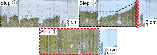
Fig. 6. Temporary plugging particle distribution during the formation of plugging layer (Mode II). |
The formation parameter combination of Mode II includes two types (Table 4 ): (1) The ratio of particle size to fracture width is 0.45, the carrier fluid viscosity is 3 mPa·s, and the carrier fluid displacement is 0.7 and 1.3 L/min. (2) The ratio of particle size to fracture width is 0.60, the carrier fluid viscosity is 3, 6 mPa·s, and the carrier fluid displacement is 0.7 L/min. In the experiment, it is observed that the plugging layer formation mode is Mode II at all temporary plugging particle mass concentrations that allow the plugging layer to form, and the change of temporary plugging particle mass concentration does not affect the plugging layer formation mode. When the ratio of particle size to fracture width is 0.45 and the temporary plugging particle mass concentration is 10 kg/m3 and 15 kg/m3, the plugging layer is not formed. The reason is that the temporary plugging particle mass concentration decreases, the number of temporary plugging particles passing through the same location of the fracture in unit time decreases, the probability of contact and collision between particles and between particles and fracture wall decreases, and the probability of temporary plugging particle bridging in the fracture decreases, making the plugging layer difficult to form. Therefore, the combination of parameters that can form the plugging layer of Mode II has nothing to do with the temporary plugging particle mass concentration. The control factors for Mode II are the ratio of particle size to fracture width, the viscosity and displacement of carrier fluid. Compared with Mode I, the viscosity of the carrier fluid in Mode II is higher, which is 3, 6 mPa·s, the capacity of the carrier fluid is stronger, and the migration distance of the temporary plugging particles along the positive direction of the fracture is longer, so the plugging layer formed is longer.
Table 4. Parameter combination of Mode II |
| Ratio of particle size to fracture width | Carrier fluid viscosity/(mPa·s) | Carrier fluid displacement/(L·min−1) | Temporary plugging particle concentration/(kg·m−3) |
|---|---|---|---|
| 0.45 | 3 | 0.7, 1.3 | 20, 40 |
| 0.60 | 3, 6 | 0.7 | 10, 20 |
The formation process of plugging layer in Mode III includes five steps (Fig. 7 ). Step ①: The temporary plugging particles accumulate discontinuously at several points along the fracture height at the same position near the fracture inlet, forming isolated plugging islands (red arrows). Step ②: The temporary plugging particles continue to accumulate in the gaps between the plugging islands, connecting the plugging islands together. Meanwhile, they continuously accumulate from bottom to top and from front to rear, forming a triangular accumulation layer gradually rising along the positive direction of the fracture. Steps ③ to ⑤: consistent with steps ② to ④ in Mode I. The temporary plugging particles entering the fracture to Step ④ is the height growth stage of the plugging layer, and Step ④ to Step ⑤ is the length growth stage of the plugging layer.
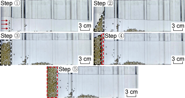
Fig. 7. Temporary plugging particle distribution during the formation of plugging layer (Mode III). |
As to the parameter combinations of Mode III: the ratio of particle size to fracture width is 0.75, the carrier fluid viscosity is 1 mPa·s, the carrier fluid displacement is 0.7, 1.3, 1.6 L/min, and the temporary plugging particle mass concentration is 5 kg/m3 and 10 kg/m3. Whether the plugging Mode III is formed or not has nothing to do with the carrier fluid displacement and the particle mass concentration. The controlling factors of Mode III are the ratio of particle size to fracture width and the carrier fluid viscosity. Compared with Mode I, the ratio of particle size to fracture width is larger, with lower difficulty in discontinuous accumulation of temporary plugging particles at multiple locations in the fracture height direction, faster particle settlement under the same conditions, and shorter migration distance along the positive direction of the fracture, so the plugging layer is shorter.
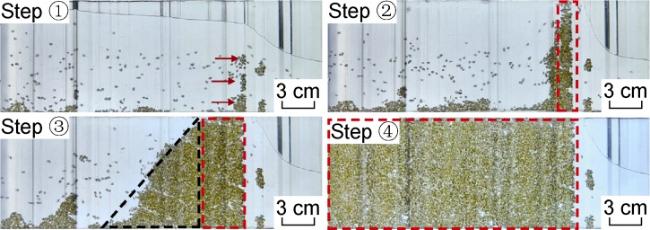
The formation process of plugging layer in Mode IV includes four steps (Fig. 8 ). Step ①: Temporary plugging particles accumulate discontinuously at multiple points along the fracture height at the same position far away from the fracture inlet, forming isolated plugging islands (red arrows). Step ②: The temporary plugging particles accumulate in the gap between the plugging islands, connecting the plugging islands together, and forming a short plugging layer in the fracture height direction. Step ③: Temporary plugging particles continuously accumulate from bottom to top and from front to rear at the rear of the plugging layer. The temporary plugging particles at the front of the plugging layer accumulate faster than those at the rear. The length of the plugging layer increases continuously. At the same time, a triangular accumulation layer rising along the positive direction of the fracture is formed at the rear of the plugging layer. Step ④: The temporary plugging particles continue to accumulate continuously between the rear of the plugging layer and the fracture inlet. The temporary plugging particles at the front of the plugging layer accumulate more slowly than those at the rear. The triangular accumulation layer gradually transforms into a rectangular plugging layer, and the length of the plugging layer increases. The temporary plugging particles entering the fracture to Step ② is the height growth stage of the plugging layer, and Step ② to Step ④ is the length growth stage of the plugging layer.
Fig. 8. Temporary plugging particle distribution during the formation of plugging layer (Mode IV). |
There are two parameter combinations of Mode IV (Table 5 ): (1) the ratio of particle size to fracture width is 0.60, the carrier fluid viscosity is 3 or 6 mPa·s, and the carrier fluid displacement is 1.3 or 1.6 L/min; (2) The ratio of particle size to fracture width is equal to 0.75, and the carrier fluid viscosity is 3 or 6 mPa·s. Similar to Mode II, in the experiment, it is observed that the plugging layer formation mode is Mode IV at temporary plugging particle mass concentrations that allow the plugging layer to form, and the change of temporary plugging particle concentration does not affect the plugging layer formation mode. When the ratio of particle size to fracture width is 0.60 and the temporary plugging particle mass concentration is 5.0 kg/m3, the plugging layer is not formed, for the same reason as that in Mode II. The controlling factors for Mode IV are the ratio of particle size to fracture width, the carrier fluid viscosity and the carrier fluid displacement. When the ratio of particle size to fracture width is 0.60, compared with Mode II, the carrier liquid displacement and carrying capacity of Mode IV are larger, the sedimentation effect of particles is weakened, the amount of suspended temporary plugging particles suspended along the fracture height is increased, the probability of discontinuous accumulation of temporary blocked particles along the fracture height is increased. Therefore, the migration distance of temporary plugging particles is longer, and the length of the plugging layer is longer. When the ratio of particle size to fracture width is 0.75, the carrier fluid viscosity is higher in Mode IV than that in Mode III, which leads to a longer plugging layer.
Table 5. Parameter combination of Mode IV |
| Ratio of particle size to fracture width | Carrier fluid viscosity/ (mPa·s) | Carrier fluid displacement/ (L·min−1) | Temporary plugging particle mass concentration/(kg·m−3) |
|---|---|---|---|
| 0.60 | 3, 6 | 1.3, 1.6 | 10, 20 |
| 0.75 | 3, 6 | 0.7, 1.3, 1.6 | 5, 10 |
Through the analysis of the formation conditions and process of the plugging layer, it can be seen that the greater the carrier fluid viscosity and displacement, the more difficult to form a plugging layer. The larger the temporary plugging particle size and mass concentration, the less difficult the formation of a plugging layer.
4. Field verification of construction parameters
Wei204H51-6 and Wei204H51-7 are two development wells on the same pad targeting the Silurian Longmaxi shale reservoirs in Weiyuan bock, Sichuan Basin. For Well Wei204H51-6, a carrier fluid with viscosity of 3-4 mPa·s and displacement of 6 m3/min was used to carry temporary plugging particles with a size of 1.0-2.0 mm, and the liquid used per meter was 31.2 m3. No temporary plugging particles were added to Well Wei204H51-7, and the liquid used per meter was 25.5 m3. The ITPDF effects of the two wells were compared and analyzed (Table 6 ): (1) Compared with Well Wei204H51-7, Wei204H51-6 demonstrates a decrease in the length of the fracture network by 2.1%, an increase in the width of the fracture network increases by 47.1%, and an increase in the number of microseismic event by 90.6%, at an increased liquid used per meter, indicating that the excessive extension of the fracture is effectively inhibited and the fracture complexity is increased. (2) Under the same construction conditions, the average pressure of Well Wei204H51-6 increases by 3.8 MPa after the temporary plugging particles are added. The above two points show that adding temporary plugging particles in Well Wei204H51-6 has obvious fracturing effect and the temporary plugging construction parameters are effective. For Well Wei204H51-6, the carrier fluid with medium viscosity and low displacement was used to pump temporary plugging particles. This method is basically consistent with the understanding of this paper, which confirms that the results of this study are reliable.
Table 6. ITPDF effect of wells Wei204H51-6 and Wei204H51-7 |
| Well | Fracture network length/m | Fracture network width/m | Number of micro-seismic events | Average pressure/ MPa |
|---|---|---|---|---|
| Wei204H51-6 | 370 | 125 | 58.7 | 3.8 |
| Wei204H51-67 | 378 | 85 | 30.8 |
5. Conclusions
The formation of plugging layer in the fracture is affected by the carrier fluid viscosity and displacement, temporary plugging particle size and mass concentration. The greater the carrier fluid viscosity and displacement, the more difficult the formation of the plugging layer. The larger the temporary plugging particle size and concentration, the less difficult the formation of the plugging layer.
The formations of plugging layer by temporary plugging particles with different sizes in fractures with the same width correspond to different construction parameter combinations. When the ratio of particle size to fracture width is 0.45, the formation of plugging layer is mainly controlled by the temporary plugging particle mass concentration and the carrier fluid viscosity. When the temporary plugging particle mass concentration is less than 20 kg/m3 or the carrier fluid viscosity is greater than 3 mPa·s, it is difficult to form a stable plugging layer. When the ratio of particle size to fracture width is 0.60, the formation of plugging layer is mainly controlled by the temporary plugging particle mass concentration, and it is difficult to form stable plugging when the temporary plugging particle mass concentration is less than 10 kg/m3. When the ratio of particle size to fracture width is 0.75, the formation of plugging layer is not affected by other parameters, and a stable plugging layer can be formed within the range of experimental conditions.
The formation process of plugging layer includes two stages and four modes. In the height growth stage of the plugging layer, the rear pressure of the plugging layer is 0 MPa. When the fracture height is blocked completely by temporary plugging particles, the rear pressure of the plugging layer starts to rise. The main controlling factors affecting the formation modes of plugging layer are the ratio of particle size to fracture width, carrier fluid displacement and carrier fluid viscosity.