

Introduction
According to the statistical data from the International Energy Agency (IEA), the atmospheric concentration of CO2 has risen dramatically since the beginning of the Industrial Revolution in 1750. In 2021, the global CO2 emissions reached a record high of 363 × 108 t [1], and the global average concentration of CO2 in the atmosphere increased to 414.72 × 10⁶. As a result, the global average temperature has risen by more than 1.1°C above pre-industrial levels, and the average ocean surface pH has declined from 8.21 to approximately 8.10. As the greenhouse effect continues to intensify, the urgency of reducing global greenhouse gas (GHG) emissions rises [2]. At present, approximately 140 government organizations have committed to a net-zero target of GHG emissions, which shows that a global consensus has grown around the vision of a carbon-neutral future [3]. According to the Intergovernmental Panel on Climate Change (IPCC) [4], carbon capture and storage (CCS) is currently the best engineering-based strategy to limit the global temperature rise to 1.5 °C above the pre-industrial eras. According to IEA [5], the global deployment of the carbon capture, utilization, and storage (CCUS) technology will reach 115 × 109 t of CO2 by 2060, with 93% of the captured CO2 being permanently stored underground, and by 2070, CCUS will be able to account for approximately 15% of the cumulative reduction in global emissions. To achieve these goals, the geological storage of CO2 would have to increase by 4000 × 104 t per year. These estimates highlight the vital role of CCUS in building a carbon-neutral future.
According to the Global CCS Institute [6], by the end of September 2022, there were more than 196 CCS/CCUS projects worldwide that were operational or in the planning and construction stage, corresponding to a 61 or 45.2% increase, respectively, relative to the same period in 2021. The global capacity of CO2 capture reached 2.44 × 10⁸ t per year, a 44.0% increase compared with 2021. The adoption of the industrial CCS/CCUS clusters is increasingly becoming commonplace, and the emergence of the regional CCS/CCUS networks, in which multiple hubs and clusters are connected via shared transportation infrastructure, will promote the widespread adoption of the CCS/CCUS technologies. Multiple demonstration projects of CCS/CCUS are already in operation around the world; for example, the CCUS industrial cluster in the Gulf of Mexico, USA (storage capacity of 100-million-ton), the CCUS facility in Alberta, Canada (storage capacity of 10-million-ton), and the CCS project in Rotterdam, the Netherlands (storage capacity of 10-million-ton) have been launched in succession. In China, China Petrochemical Corporation has launched a 10-million-ton open-source cluster project of CCUS in East China; the China National Offshore Oil Corporation has initiated research on 10-million-ton offshore storage; and the China National Petroleum Corporation has launched four major demonstration projects of CCUS-enhanced oil recovery (EOR) and six pilot test projects of CCUS-EOR. Evident from the above projects is that the CCS/CCUS industry in China has entered a rapid development stage of 10-million-ton demonstration projects of CCS/CCUS [7-8].
In this context, the assessment of CO2 storage capacity of geological formations is the key to the large-scale adoption of the CCS/CCUS technologies. However, the currently available assessment methods substantially differ from one another. Based on the specific requirements of different projects, the assessment of storage potential can be carried out on the national, basin, regional, local, and site scales. Based on the type and amount of data used in the assessment, potential storage capacity can be categorized into the theoretical, effective, practical, and matched types. As the assessment methods change from estimations to actuarial methods, the assessment accuracy increases gradually. According to their approach, the assessment methods of carbon storage capacity can be grouped into volumetric methods, storage mechanism characterization-based methods, compression coefficient-based methods, dimensionless parameter analysis, and dynamic simulations [9⇓⇓-12]. As the common approach to the storage assessment, the volumetric methods have been used by the Carbon Sequestration Leadership Forum (CSFL), the United States (US) Department of Energy (DOE), the IEA Greenhouse Gas (IEA GHG) Research and Development (R&D) Program, and the US Geological Survey (USGS) [13⇓⇓-16]. The volumetric approach is based on assessment methods used in the oil and gas industry, which estimate the static storage capacity from geological factors. The static storage capacity depends on the values of storage efficiency coefficients, which can vary by tens or even hundreds of times [17⇓⇓-20]. This approach is applicable in the early stages of resource evaluation and planning; however, its usefulness remains greatly limited for the current stage of the large-scale implementation of CCS.
As the CCS/CCUS program of China enters into the implementation stage of the large-scale CCS/CCUS projects, the focus of the storage capacity assessment should not be on the basin scale but on the premise of having sufficient and accurate data. In addition, priority should be given to petroliferous basins favorable for CO2 storage, such as depressions, belts, and strata, to determine optimal target areas for the implementation of the demonstration projects. The assessment should also include the impacts of engineering (e.g., safety constraints, pressure constraints, injection capacity, and time dependence), economic, and policy-related factors on the storage capacity. There is a pressing need to establish an assessment model that can determine the potential and implementable storage capacity of geological formations in petroliferous basins to satisfy the needs of large-scale engineering projects. This study proposes an assessment model of carbon storage capacity of geological formations in petroliferous basins. The proposed model can provide the basis for the implementation and application of the dual carbon policy objectives of carbon peaking and carbon neutrality of China.
1. Assessment of CO2 storage capacity of petroliferous basins
Petroliferous basins are the crustal sedimentary basins with uniform geology, in which the presence of oil and gas fields has been confirmed. They are the basic geological units of generation, migration, and accumulation of petroleum resources. Owing to their abundant geological data and well-established geological parameters, the assessment of storage capacity of petroliferous basins can produce relatively reliable results. At the same time, the availability of mature and economically feasible carbon storage technology makes petroliferous basins prime sites for the large-scale carbon storage projects. This study proposed a four-scale and three-type assessment model of carbon storage capacity of petroliferous basins aiming to meet the needs of the large-scale CCS/CCUS implementation. The proposed model determined the potential storage capacity of saline aquifers in petroliferous basins based on a comprehensive consideration of geological, engineering, and economic constraints.
1.1. Scale-based assessment of CO2 storage capacity of geological formations
The assessment of CO2 storage in geological formations based on the structural units of petroliferous basins can be classified into the basin, depression, zone, and trap levels (Fig. 1 ). The basin level refers to typically petroliferous sedimentary basins, rich in petroleum resources and underground saline aquifers, such as Songliao, Bohai, Subei-Nanhuanghai, Sichuan, Ordos, Junggar, Tarim, Qaidam, East China Sea, and Zhujiangkou basins. These basins are the key regions for the development of the CCS/CCUS clusters. A depression is a first-order structural unit of a basin. Depressions are regions associated with the deepest sedimentation, where the sedimentary deposits are thick and well preserved, such as in Jiyang, Dongpu, Liaohe, and Huanghua depressions. Depressions are highly suitable for the large-scale development of CO2 storage clusters. A belt is a secondary structural unit of a basin along a single regional structure and consists of similar-type source-reservoir-cap assemblages. Belts can be composed of several local structures of the same origin, such as placanticline, anticline, syncline and fault. Belts are favorable areas for large-scale CO2 storage in geological formations. Traps are a third-order structural unit. The most common structural traps are anticlines, synclines, and structural noses. Since traps are the basic structural units associated with the formation of oil and gas fields, they are the target areas for the CO2 storage projects. Multiple traps can form a belt with favorable storage conditions, several belts can form a potential depression-storage area, and several depressions can form a potential basin-storage area.
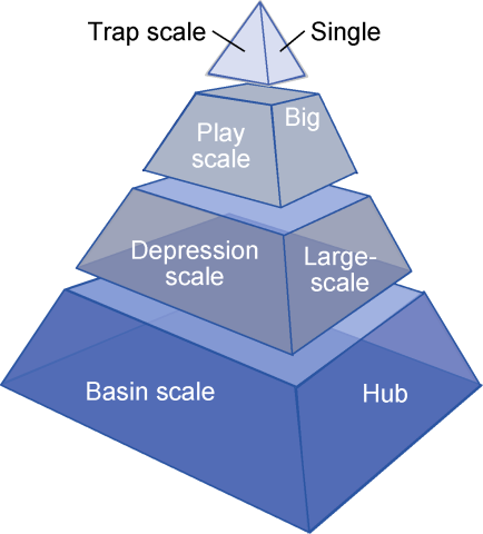
Fig. 1. Scale-based assessment of CO2 storage capacity of petroliferous basins. |
1.2. Type-based assessment of CO2 storage capacity
The CO2 storage capacity of saline aquifers in petroliferous basins can be divided into theoretical, engineering, and economic types (Fig. 2 ). The primary factors considered before the implementation of the large-scale CCS/CCUS projects are safety and economic favorability of storage sites.
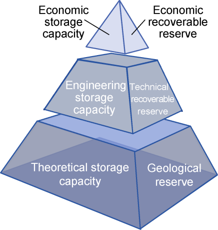
Fig. 2. Resource classification-based assessment of CO2 storage capacity of petroliferous basins. |
Theoretical CO2 storage capacity represents the maximum effective storage of resources estimated from static geological parameters, including the sedimentary environment, structural characteristics, and physical properties of a reservoir bed in a target area. Due to large uncertainties in the geological conditions, the representative values of different parameters can be selected by using the Monte Carlo analysis or weighted analogy models, and the assessment can be carried out via approximation algorithms. The key when this assessment type is applied is to reduce the uncertainties in the geological parameters by using seismic data, well-logging data, and detailed reservoir bed data, thereby obtaining a relatively realistic estimation of storage capacity. The assessment of theoretical storage capacity is comparable to the estimation of geological reserves used in the development of oil and gas fields and should be treated as a theoretical reference value for further assessing storage capacity.
Engineering storage capacity represents the storage capacity calculated based on parameters related to actual project implementation, including safety-related factors, number of wells, and other factors. Among safety-related factors, injection capacity and maximum sustainable storage pressure, which are related to reservoir/caprock properties and fault sealing characteristics, are the most important parameters. In general, engineering storage capacity is spatiotemporally dynamic. As time passes, the dynamic storage capacity infinitely approaches the maximum engineering storage capacity. This assessment method involves the concepts of a single-well-controlled storage and a single-well-controlled area; the single-well-controlled storage capacity and the number of wells to be deployed are determined based on the actual injection capacity and maximum sustainable storage of the target area and are subsequently used to calculate the engineering storage capacity of the target area. This assessment method requires the use of relatively comprehensive geological parameters and actuarial analysis and can be used to rapidly assess storage before the implementation of specific projects and provide a design reference for the CCS/CCUS projects. Comparable to technically recoverable reserves, engineering storage capacity refers to the theoretical storage capacity that can feasibly be obtained using currently available technology and industrial practices and is the conditions under which the project implementation would be feasible.
The assessment of economic storage capacity involves determining the economically feasible storage capacity of the target area by using the previously determined engineering storage capacity to comprehensively consider different economic factors, including carbon cost-benefits, investment costs, and operating costs of the project. Among these, carbon cost-benefits include carbon trading price, carbon tax, carbon subsidies, and other potential benefits. The investment costs include fixed costs, such as well drilling and completion and pipeline installation cost, while the operating costs include pressurized injection and captured gas reinjection costs. Economic CO2 storage capacity involves costs and benefits related to geological, engineering, and economic aspects of the CCS/CCUS projects. Therefore, this type of assessment requires a model that integrates technical and economic factors to effectively evaluate the economic favorability of a project based on the break-even principle. The economic storage capacity provides an economic analysis of the project implementation with the goal of minimizing the cost of carbon storage. Comparable to economically recoverable reserves, economic storage capacity represents the storage capacity of some projects under economically feasible conditions and is the preferential type of the storage capacity deployment.
For actual applications, the theoretical storage assessment is generally carried out only at the basin and depression levels (large scale). This type of assessment can be used for the regional-scale screening of storage potential. For the belt- and trap-level assessments (small and medium scales, respectively), under the premise that sufficient and accurate geological data, engineering parameters, and economic conditions are available, the assessment of engineering and economic storage capacities can be carried out as required by specific projects, and the assessment results can be used as a reference for the project implementation in the target area. The above four-scale and three-type assessment method of the storage potential can be used as a reference for evaluating the CO2 storage capacity of petroliferous basins.
2. Assessment model of CO2 storage capacity of petroliferous basins
Each level of the three-type assessment method of CO2 storage capacity of petroliferous basins has a different objective; thus, at each assessment level, the influencing factors of storage capacity should comprehensively be considered in terms of effective constraints suitable for the desired assessment objective.
2.1. Assessment model of theoretical storage capacity
The theoretical storage capacity of saline aquifers can be evaluated using the sequestration mechanism method since the geological parameters of petroliferous basins are well established, and the development data of oil and gas fields are relatively abundant. The sequestration mechanism involves four types of action; namely, structural trapping, residual trapping, solubility trapping, and mineral trapping. These actions are affected by structural parameters and physical and fluid properties of reservoirs. The specific evaluation method is as follows:
To evaluate the structural trapping mechanism of CO2 in saline aquifers, if the aquifer is an open reservoir, the structural storage capacity is presented as follows [9]:
For the open reservoirs, if the storage coefficient is unknown, the simulation results of the petroliferous basins in North America obtained by the US DOE can be used as a reference [21] (Table 1 ).
Table 1. Prediction of storage coefficient under different lithological conditions [21] |
| Lithology | Regional scale/% | Saltwater scale /% | ||||
|---|---|---|---|---|---|---|
| P10 | P50 | P90 | P10 | P50 | P90 | |
| Clastic rock | 3.1 | 6.1 | 10.0 | 1.2 | 2.4 | 4.1 |
| Dolomite | 5.1 | 6.9 | 9.2 | 2.0 | 2.7 | 3.6 |
| Limestone | 3.5 | 5.2 | 7.3 | 1.3 | 2.0 | 2.8 |
Note: P10, P50, and P90 are the confidence intervals in the Monte Carlo simulation. |
For the closed reservoirs, the theoretical CO2 storage capacity depends on the comprehensive compressibility coefficient of the formation of water and rock as well as the initial and final pressures of the formation; thus, the storage coefficient is defined as follows [10]:
The corresponding storage capacity is expressed as follows:
Residual trapping occurs after water injection when the free gas stored through structural trapping is sealed by water intrusion as a discontinuous-phase gas in the formation. This type of storage capacity is calculated using the lag coefficient of drainage/relative permeability curve [9] as follows:
Solubility trapping refers to the amount of dissolved gas in the regional formation of water after CO2 injection, which is described as follows [9]:
Mineral trapping mainly refers to the dissolution of carbonate minerals in the CO2 injection, with its storage capacity thus defined as follows:
where
2.2. Assessment model of engineering storage capacity
Engineering storage capacity is the effective storage capacity that can be feasibly implemented using currently available technologies based on the theoretical capacity, with priority being given to safety. The engineering storage capacity is affected by different factors and parameters, such as the injectivity index, pressure limit, injection time, and the number of wells. The engineering storage capacity is provided as follows:
During the implementation of the CCS/CCUS projects, multiple wells must be deployed to effectively control the theoretical storage capacity. The layout of wells is based on the principle that when the reservoir pressure reaches its maximum sustainable pressure during CO2 injection, the CO2 gas chamber of a single well will have reached its maximum expansion range. When multiple wells are deployed, there should be no mutual interference between the maximum expansion areas of CO2 gas chambers of adjacent wells, and the entire expansion area of each CO2 gas chamber will be located within the target area to maximize the CO2 storage capacity of the engineering project.
To calculate the engineering storage capacity, the characteristic storage capacity of a single well (the storage capacity that can be obtained by a single well) is used as follows:
The effective engineering storage of a single well (Eu) represents the comprehensive effect of the sweep and displacement efficiencies of CO2 injection. The empirical equation for the effective engineering storage of a single well in different types of reservoirs can be obtained either through the methods of numerical simulations and statistical analyses or from the empirical equation in Ravi Ganesh et al. [22].
The values of β and γ can be obtained from the gas-water relative permeability curves, which are experimentally derived from the relationship between gas content and gas saturation, thus determining the rate of change in gas content with gas saturation.
The maximum allowable injection rate can be estimated from the injectivity index and pressure change as follows:
For specific projects, the injectivity index can be obtained experimentally via numerical simulations or the engineering analogy method.
The safety limit of storage pressure can be determined either based on the minimum experimental values of rock-fracture pressure, cap-rock breakthrough pressure, and fault-activation pressure or via the empirical equation based on the maximum sustainable injection pressure of the reservoir and the injectivity index [22] as follows:
The actual injection storage capacity of a single well is expressed as follows:
When the characteristic storage capacity of a single well equals its actual injection storage capacity, that is, Mu = mu, the storage area controlled by a single well can be obtained by combining Eqs. (12) and (19) as follows:
To ensure that CO2 storage is fully contained in the target area, the number of deployment wells is calculated as follows:
Finally, the actual engineering storage capacity is expressed as follows:
2.3. Evaluation of economic storage capacity
The economic storage capacity is derived from the engineering storage capacity by comprehensively considering different economic constraints, including carbon cost-benefit, investment cost, and operating cost, and can be expressed as follows:
The above influencing factors can be simplified to the following three main types: carbon cost-benefit, fixed investment and operating cost, and input into the optimization function of the target economic benefit [23].
The economic storage capacity is estimated as follows:
If CO2 leakage is ignored, that is, Ml = 0, then Eqs. (24) and (25) can be combined to obtain the following:
When the target benefit function of carbon storage f = 0, we can obtain the critical CO2 storage capacity at the break-even point of the project investment and output; that is, the critical economic CO2 storage capacity, below which the project is no longer economically feasible.
In combination with Eq. (22), we can obtain the critical economic storage coefficient, which represents the ratio of critical economic storage capacity to actual engineering storage capacity:
The economic storage capacity can be expressed as follows:
3. A case study of assessment of carbon storage capacity of petroliferous basins
3.1. Physical parameters of the saline aquifer in the target region
In the present study, we selected a saline aquifer in the Gaoyou sag of the Subei basin. The 480-m-thick aquifer showed a burial depth of 2200 m, an area of 4.43 km2, porosity of 24.6%, and permeability of 356.5 × 10⁻³ μm2. The reservoir temperature and pressure were 80 °C and 22.3 MPa, while the aquifer salinity and carbonate content were 30 g/L and 10%, respectively. The aquifer was characterized by high porosity, high permeability, large effective thickness, a moderate burial depth, and a relatively high carbonate content. After the initial screening, the aquifer was determined suitable for storage capacity assessment.
3.2. Classification-based assessment of carbon storage capacity of saline aquifers
The present assessment method was used to calculate the different types of carbon storage capacity of the saline aquifer. The theoretical storage capacity of the reservoir was estimated at 25.93 × 10⁶ t. In particular, the structural, solubility, residual, and mineral storage capacities were determined as 13.04 × 10⁶, 8.52 × 10⁶, 4.24 × 10⁶ and 0.13 × 10⁶ t (50.3%, 32.9%, 16.4%, and 0.5% of the theoretical storage capacity), respectively. The engineering storage capacity of the reservoir was 5.44 × 10⁶ t, only 21.0% of the theoretical storage capacity. The results showed that the structural storage is the dominant type of storage, followed by the solubility, residual, and mineral storage. The engineering storage capacity was significantly lower than the theoretical storage capacity since it was constrained by the safety considerations and engineering feasibility objectives.
To calculate the economic storage capacity, it is necessary to determine carbon cost-benefit (where, for example, carbon trading price and tax subsidies can be used), the deployment cost of a single well, and the unit operating cost of CO2 injection. Ignoring the carbon-energy price and the monitoring cost in the later stages of the project, domestic market price in China was RMB 50-120/t; thus, in subsequent calculations, we used an average value of RMB 85/t. The drilling cost of a horizontal well ranged from RMB 2000 × 104 to RMB 3000 × 104 per well, varying with drilling depth and the length of the horizontal section. The unit operating cost of CO2 injection represented the cost of CO2 injection in oilfields, approximately RMB 80/t.
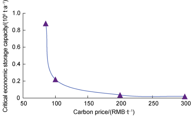
Based on the investment costs and benefits combined with the physical parameters of the target saline aquifer, we calculated the critical economic storage capacity under different carbon cost-benefit conditions (Fig. 3 ). Evident from Fig. 3 is that the critical economic storage capacity gradually rose as the carbon cost-benefit fell; when the carbon cost-benefit was less than RMB 100/t, the critical economic storage capacity rose sharply. The fitting function of the above curve represented the empirical relationship between the critical economic storage capacity of the saline aquifer and the carbon cost-benefit, with its coefficient of determination (R2) value of 0.999 15 indicating a good fit.
Fig. 3. The curve of the critical economic storage capacity under different carbon cost-benefit conditions. |
Eq. (30) was used to calculate the critical storage capacity of a single well in a saline reservoir under different carbon cost-benefit conditions, and by combining Eqs. (28) and (29), the economic storage capacity of saline reservoirs was obtained. When the carbon cost-benefit was RMB 85/t, by only considering the injection cost, and with the critical economic storage coefficient being taken as 0.16, the economic CO2 storage capacity of the saline aquifer was estimated at 4.57 × 10⁶ t, only 17.6% of the theoretical storage capacity. As the carbon cost-benefit rose, the critical economic storage capacity fell, whereas the economic storage capacity grew.
4. Conclusions
The storage capacity of petroliferous basins can be assessed at the basin, depression, belt, and trap levels and categorized into the three types of the theoretical, engineering, and economic storage capacities.
The assessment of carbon storage capacity of saline reservoirs in petroliferous basins focuses on the engineering and economic storage capacities. The engineering storage capacity is affected by the injection capacity, safe storage pressure, number of wells, and injection time. The economic storage capacity is a function of the following three main factors: carbon cost-benefit, well drilling cost, and well operating cost.
In the theoretical CO2 storage capacity of the saline reservoir, the structural storage was found to account for the largest proportion, followed by the solubility, residual, and mineral storage. The engineering and economic storage capacities of the saline aquifer, which comprehensively considered the injection capacity, project safety, and economic feasibility of the actual project, were significantly lower than the theoretical storage capacity; for example, the engineering and economic storage capacities of the Gaoyou sag in the Subei basin were only 21.0% and 17.6% of the theoretical storage capacity, respectively.
Nomenclature
A—reservoir area, m2;
Au—single well sealed control area, m2;
C—CO2 lag coefficient of drainage/imbibition phase permeability curve, dimensionless;
Ct—comprehensive compressibility coefficient of reservoir, MPa−1;
Cuw—single well investment cost, yuan;
E—structural storage coefficient, dimensionless;
EA—effective area coefficient, dimensionless;
Ec—effective compression storage coefficient, dimensionless;
Ed—displacement efficiency, dimensionless;
EH—effective thickness coefficient, dimensionless;
$E_{\varphi}$—effective porosity coefficient, dimensionless;
Eu—single well engineering storage efficiency, dimensionless;
Ev—sweep coefficient, dimensionless;
f—economic benefit target optimization function, yuan;
fg—gas fraction, %;
F(x)—function;
gz—gravity constant, N/kg;
H—reservoir thickness, m;
i—reservoir number;
J—CO2 injection index, kg/(MPa•a);
K—reservoir permeability, 10−3 μm2;
mc,i—mass fraction of carbonate in the i-th reservoir in the target area, %;
mu—injection and storage capacity of a single well, kg;
Mca—mass of carbonate minerals in reservoir rocks, kg;
$M_{CO_{2}}$—molar mass of CO2, kg/mol;
Mem—economic storage capacity, kg;
Memc—critical economic storage capacity, kg;
Memc1—critical economic storage capacity in a saline layer in the Subei Basin, kg;
Miu—single well CO2 injection, kg;
Ml—single well CO2 leakage, kg/well;
Mps—theoretical storage capacity, kg;
Mpt—engineering storage capacity, kg;
Mst—structural storage capacity, kg;
Mrs—bound storage capacity, kg;
Mds—dissolved storage capacity, kg;
Mm—mineralized storage capacity, kg;
Mst0—effective storage capacity produced by compression, kg;
Mu—single well storage capacity, kg;
n—number of wells;
Ng—gravity constant during gas injection, dimensionless;
p0—original formation pressure, MPa;
pf—safety limit pressure for storage, MPa;
pmax—maximum allowable injection pressure of the reservoir, Pa;
ps—surface wellhead pressure, Pa;
$\Delta p$—reservoir pressure change after CO2 injection, MPa;
Q—CO2 injection rate, kg/a;
rca—dissolution rate of carbonate minerals, mol/(m2•a);
Rop—investment and operating cost, RMB/kg;
Rpr—carbon cost-benefit, RMB/kg;
Rw—solubility of CO2 in reservoir water, kg/kg;
S—specific surface area of reservoir rock, m2/kg;
Sg—CO2 saturation, %;
Sgmax—maximum imbibition/drainage saturation, %;
Sirr—irreducible water saturation, %;
∆Srg—change in residual gas saturation at imbibition/drainage, %;
t—injection time, a;
w—number of reservoirs;
x—function variable;
xf—dissolution coefficient of CO2 in water, dimensionless;
z—reservoir burial depth, m;
α—critical economic storage coefficient, dimensionless;
β, γ—coefficients derived from the curve of the relationship between gas content and gas saturation, dimensionless;
ϕ—reservoir porosity, %;
$\rho CO_{2}$—CO2 density under reservoir conditions, kg/m3;
ρf—fluid density, kg/m3;
ρs—rock density of reservoir overburden, kg/m3;
ρi—rock density of each reservoir in the target area, kg/m3;
ωst, ωrs, ωds, and ωm—influencing factors related to structural, residual, solubility, and mineral trapping, respectively;
ωpr, ωiv, ωop, and ωin—influencing factors related to carbon cost-benefit, fixed investment, operating cost, and CO2 injection, respectively.