

Introduction
The ultra-short radius radial horizontal borehole technology is considered to be a revolutionary technology for effective drilling in the 21st century [1⇓-3]. Radial borehole fracturing combines radial boreholes with hydraulic fracturing to improve the communication between radial boreholes and reservoirs [4⇓⇓⇓⇓-9]. It has been successfully applied in many oilfields in China and abroad [10⇓-12], and has remarkably improved production. The process principle is: first, drill radial borehole in multiple layers with different orientations and lengths perpendicular to the axis of the main wellbore, and then implement hydraulic fracturing, and finally form a complex radial borehole fracture network in the reservoir [13]. Studying the fracture propagation of radial borehole fracturing is of great significance to optimize the spatial layout of radial boreholes and form a complex radial borehole fracture network, so as to realize the economical and efficient drilling of oil and gas.
Scholars have done a lot of research work in radial borehole fracturing and fracture propagation: Fu et al. [14] carried out true-axis fracturing experiments in a natural coal rock radial borehole, and explored the influence of radial borehole length, numbers and azimuth on fracture fracturing and propagation. The experimental results of Lu et al. [15] showed that radial boreholes could induce fracture initiation and propagation. Yan et al. [16] carried out a triaxial fracturing chamber experiment in a single radial borehole, and the results showed that the greater the angle between the radial borehole and the maximum horizontal stress direction, the greater the breakdown pressure of the rock and the extension pressure of the fracture, and the more complex the fracture. Liu et al. [17] carried out a triaxial fracturing chamber experiment in fracturing multiple radial boreholes in one layer, and the results showed that multiple radial boreholes could induce multiple fracture propagation. Tian et al. [18] considered the influence of the plastic zone around the wellbore and proposed the criterion of fracture-induced directional propagation of fractures induced by fracturing in radial boreholes. Guo et al. [19] carried out radial borehole fracturing experiments to explore the influencing factors and laws of breakdown pressure and fracture propagation. Due to the short length of the radial borehole used in the experiment, it is not possible to accurately restore the synchronous fracturing process of the radial borehole under reservoir conditions, so it is particularly important to carry out relevant numerical simulation studies.
In terms of numerical simulation of fracture propagation in radial boreholes, Guo et al. [20] established a finite element model of quasi-radial borehole propagation of fracturing fractures in a single radial borehole, and analyzed the influence of horizontal principal stress difference, radial borehole orientation, length, reservoir elastic modulus, Poisson's ratio, etc. on fracture geometries. Liu and Tian [21] used the finite element method to analyze the influences of azimuth, length, diameter and vertical principal stress and the maximum horizontal stress of the radial borehole. Wang et al. [22] used the ABAQUS software to study the influence of azimuth, numbers and in-situ stress state of radial boreholes on the fracturing pressure and fracturing position of fracturing multiple radial boreholes in one layer, and compared the simulation results with the experimental results of fracturing multiple radial boreholes in one layer. It showed that the key factor for multiple radial boreholes to induce the expansion of multiple fractures was the azimuth. Although there have been a lot of studies on the numerical simulation of fracture propagation in radial boreholes, few studies have considered the influence of multi-layer multi-branch radial boreholes on fracture propagation.
The numerical simulation methods of hydraulic fracturing fracture propagation include finite element method, extended finite element method, discrete element method and boundary element method [23⇓⇓⇓⇓-28]. Numerical simulation of radial borehole fracturing fracture propagation mainly adopts the extended finite element method of ABAQUS software. The traditional finite element method can deal with nonlinear and complex boundary problems in the model, but it is expensive to re-mesh after fracture propagation [29]. The meshless method eliminates the need to re-mesh when dealing with fracture propagation, effectively reducing computational costs. Therefore, the finite element-meshless method can be used to combine the advantages of both to simulate radial borehole fracture propagation.
Considering the coupling effect of fracturing fluid flow and rock matrix deformation, the finite element-meshless method is used to establish a radial borehole fracturing fracture propagation model, and the fluid-structure interaction solution model is based on the TOUGH3 fluid solver and the AIFRAC solid solver. The fracture geometries of radial borehole fracturing under reservoir conditions are simulated, the guiding effect of radial boreholes on fractures is analyzed, and the evolution of fracture geometries under different azimuths, horizontal principal stress differences and rock matrix permeability is studied. The research provides a theoretical basis for improving the reservoir stimulation of radial borehole fracturing technology.
1. Radial borehole fracturing fracture propagation model
1.1. Model assumptions
(1) The rock matrix is continuous, homogeneous and isotropic materials. (2) Fracture propagation can be regarded as a quasi-static process. (3) Fracking fluid is an incompressible Newtonian fluid. (4) Radial boreholes usually need to pass through the casing, so the filtration loss of fracturing fluid into the rock matrix in the main wellbore is ignored. (5) The radial borehole is replaced by a weakened material, and the fracturing fluid in the radial borehole can be filtered into the rock matrix. (6) Constant pressure injection of fracturing fluid.
1.2. Model governing equation
Based on the above assumptions, the finite element- meshless method is used to establish the fracture propagation model, and the seepage effect of fracturing fluid is considered. The TOUGH3 fluid solver is used to calculate the fluid flow in the fracture and matrix, and the matrix deformation and fracture propagation are calculated using the AIFRAC solid solver to simulate the radial borehole propagation process of the fracture in the reservoir.
1.2.1. Solid-phase control equations
Suppose there is a three-dimensional solid Ω with fracture surface Γs in the solid, the existing tensile force t acts on the outer boundary Γh of Ω, and the loading of the tensile force can be regarded as a quasi-static process. The strong form of the solid-phase control equation is shown in Eqs. (1) and (2).
In Ω,
$\nabla \times \sigma +b=0$
In Γh,
$\sigma \times v\text{=}h$
During the fracturing process, the external loads on both sides of the fracture surface Γs must be equal [29], the displacement difference between the positive and negative sides of the local fracture surface is called the displacement interval, and the calculation formula of the surface energy of the fracture surface is:
${{G}_{\text{s}}}=\int_{{{\Gamma }_{\text{s}}}}{p\times w\text{d}\Gamma }$
According to the principle of virtual work, the weak form of the solid-phase control equation can be obtained as:
$\int_{\Omega }{\delta {{\varepsilon }^{\text{T}}}\times \sigma \text{d}\Omega }=\int_{\Omega }{\delta {{u}^{\text{T}}}\times b\text{d}\Omega }+\int_{{{\Gamma }_{\text{h}}}}{\delta {{u}^{\text{T}}}\times t\text{d}\Gamma }+\int_{{{\Gamma }_{\text{s}}}}{p\times w\text{d}\Gamma }$
1.2.2. Fluid control equations
The mass balance equation for fluid flow is:
$\frac{\text{d}}{\text{d}t}\int{{{M}_{k}}\text{d}{{V}_{\text{n}}}}=\int{{{F}_{k}}\cdot n\text{d}{{\Gamma }_{\text{n}}}}+\int{{{q}_{k}}\text{d}{{V}_{\text{n}}}}$
where ${{M}_{k}}=\phi \sum\limits_{\beta }{{{S}_{\beta }}{{\rho }_{\beta }}{{X}_{\beta,k}}}+\left( 1-\phi \right){{\rho }_{\text{r}}}{{\rho }_{l}}{{X}_{l,k}}{{K}_{\text{d}}}$
The mass flow of component k consists of convection flow and diffusion flow, where the expression of convection flow is:
${{F}_{k,}}_{\text{adv}}=\sum\limits_{\beta }{{{X}_{\beta,k}}{{F}_{\beta }}}$
The flow rate of a single liquid phase β can be given by the multiphase formula of Darcy's law:
${{F}_{\beta }}=-K\frac{{{K}_{\text{r}\beta }}{{\rho }_{\beta }}}{{{\mu }_{\beta }}}\left( \nabla {{p}_{\beta }}-{{\rho }_{\beta }}g \right)$
The diffusion flow is calculated as:
${{f}_{\beta,k}}=-\phi {{\tau }_{0}}{{\tau }_{\beta }}{{\rho }_{\beta }}{{d}_{\beta,k}}\nabla {{X}_{\beta,k}}$
1.2.3. Fracture propagation criteria
Fracture propagation simulation needs to determine the fracture propagation direction first. The AIFRAC solid solver adopts the maximum circumferential stress criterion, and the fracture propagation angle calculation formula is:
$K_{\mathrm{P}} \sin \theta_{0}+K_{\mathrm{II}}\left(3 \cos \theta_{0}-1\right)=0 \quad\left(-\pi \leq \theta_{0} \leq \pi\right)$
In Eq. (9), the formula [29] for calculating the stress intensity factor is:
$\left\{ \begin{align} & {{K}_{}}=\sqrt{\frac{2\pi }{{{r}_{\text{m}}}}}\frac{E}{2\left( 1+\upsilon \right)}\frac{1}{\kappa +1}\Delta {{v}_{}} \\ & {{K}_{}}=\sqrt{\frac{2\pi }{{{r}_{\text{m}}}}}\frac{E}{2\left( 1+\upsilon \right)}\frac{1}{\kappa +1}\Delta {{v}_{}} \\\end{align} \right.$
After simplification, you can get:
$\tan \left(\frac{\theta_{0}}{2}\right)=\frac{1}{4}\left[\frac{K_{\mathrm{I}}}{K_{\mathrm{II}}}-\operatorname{sgn}\left(K_{\mathrm{II}}\right) \sqrt{\left(\frac{K_{\mathrm{I}}}{K_{\mathrm{II}}}\right)^{2}+8}\right]$
1.3. Model parameters
The model is a double-deck radial borehole, with two radial boreholes distributed in each layer. Two distribution methods are studied, symmetrically along the direction of the minimum horizontal stress and the direction of the maximum horizontal stress, and the changes of four azimuths are studied under each distribution mode, as shown in Fig. 1 . The azimuth is set to 2° or 88° because the TOUGH3 fluid solver needs to divide the model into orthogonal hexahedral meshes, while the AIFRAC solid solver needs to break down the divided hexahedral meshes into tetrahedral meshes. If the azimuth is set to 0° or 90°, the hexahedral mesh cannot be decomposed into tetrahedrons. So the azimuth is slightly modified to determine the eight azimuths shown in Fig. 1 .
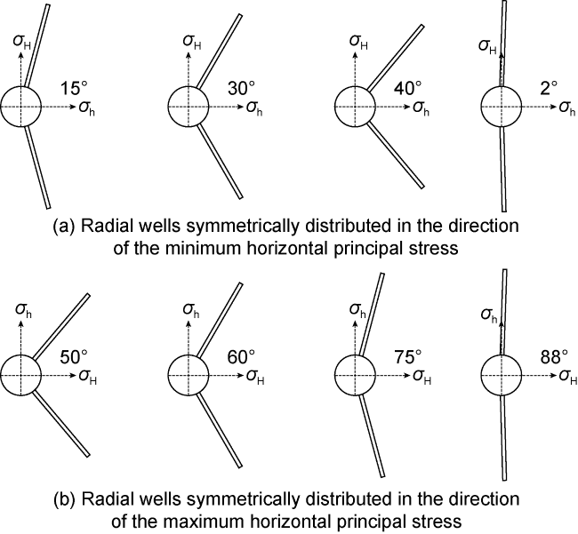
Fig. 1. Schematic diagram of the layout of two radial boreholes radial boreholes on the same floor. |
When calculating fluid flow using the TOUGH3 fluid solver, the number of hexahedral elements should be controlled within 1×10⁵, and the length of the radial borehole should not be less than 10 m during simulation, so the model size and mesh size should be controlled within a reasonable range [29]. Therefore, the influence of the grid size of the perimeter infill zone of the radial borehole along the axial direction of the radial borehole and perpendicular to the axial direction of the radial borehole on the simulation results is analyzed, and three grid sizes of this area are selected, which are 0.2, 0.3 and 0.4 m, and the grid sizes of the other areas remain unchanged, as shown in Fig. 2 .
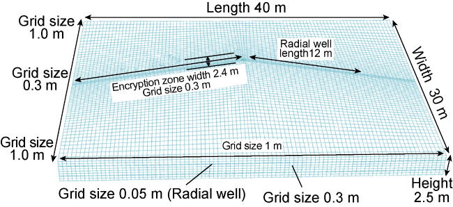
Fig. 2. Schematic diagram of model size and mesh size. |
To analyze the influence of the grid size around the radial borehole on the simulation results, the radial borehole fracture data is extracted, and the fracture data passing through the axis of the single-layer radial borehole are selected and plotted as a two-dimensional fracture. The results are shown in Fig. 3 . When the azimuth is 30°, above the minimum horizontal stress direction line, the fracture trajectories of 0.3 m and 0.4 m in the grid size coincide highly, and the fracture turns to the maximum horizontal stress direction in advance under the grid size of 0.2 m. Below the minimum horizontal stress direction line, the fracture geometries of 0.3 m and 0.4 m of mesh size are similar, while the fracture geometries of 0.2 m of mesh size are different. When the azimuth is 60°, the fracture trajectories of 0.3 m and 0.4 m of grid size coincide highly. Considering the sensitivity of model size and grid size, 0.3 m is selected as the mesh size of the surrounding infill zone of the radial borehole.
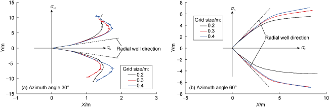
Fig. 3. Two-dimensional fracture geometries under different mesh sizes. |
Taking into account the grid size, the upper limit of the number of hexahedral elements and the actual state of the radial borehole in the formation, the size and mesh size of the model are set as shown in Fig. 2 . The diameter of the main wellbore is 0.19 m, the length of the radial borehole is 12 m, and the diameter is 0.05 m [11-12,30 -31]. In the model, two layers of radial boreholes are distributed, the vertical spacing is 1.2 m, and the distance between each radial borehole and the upper and lower boundaries of the reservoir is 0.6 m. In addition, loads are applied at the outer boundaries of the model to characterize the original in-situ stress field.
In this model, the preset fractures are vertical fractures that pass through the heel end of the radial borehole and coincide with the axis of the radial borehole. The length of the preset fracture is 1.2 m, the height is 2.5 m, and the grid size is 0.4 m. In addition, the step size of fracture propagation is 0.5 m. In this paper, tight sandstone reservoirs in the Ordos Basin are selected as the research object, and the specific mechanical parameters are investigated from the published literature [32-33]. The reservoir thickness is 2.5 m, the density is 2467 kg/m3, the elastic modulus is 32×109 Pa, the uniaxial tensile strength is 4.8×10⁶ Pa, the Poisson's ratio is 0.18, the porosity is 8%, the permeability is 0.5×10⁻³ μm2, the pore pressure is 15.6×10⁶ Pa, the maximum horizontal stress is 30×106 Pa, and the minimum horizontal stress is 25×106 Pa.
1.4. Model validation
The finite element method used in this paper has been theoretically verified in simulating fractures [29]. In order to study the feasibility of the model, the changes of fracture propagation morphology are considered when the azimuths are 75° and 88°, as shown in Fig. 4 . It can be seen that the fracture located above the maximum horizontal stress direction line deviates from the initial direction and gradually turns to the direction of the minimum horizontal stress, and then gradually turns to the direction of the maximum horizontal stress. The fracture not only has one turn, because the induction effect of the radial borehole on the fracture. This is consistent with the conclusion of radial borehole fracturing experiment using true triaxial fracturing experimental device [19], that is, radial borehole fracturing can induce the fracture to propagate along the axial direction of the radial borehole, and the fracture gradually turns to the direction of minimum horizontal principal stress after deviating from the radial borehole. It shows that it is feasible to use the model in this paper to study the fracture propagation of radial borehole fracturing.
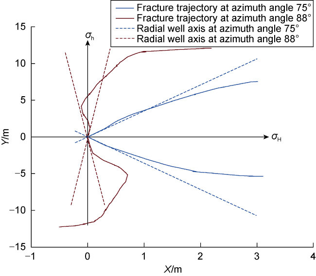
Fig. 4. Local magnification of fracture geometries at azimuths of 75° and 88°. |
2. Deviation distance and radial borehole-to- well extrusion
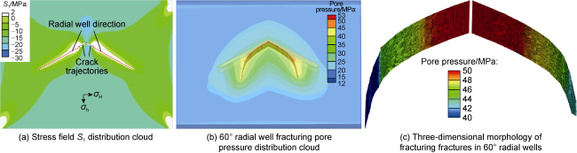
Fig. 5. Model stress field S1 distribution cloud, 60° radial borehole fracturing pore pressure distribution cloud and radial borehole fracture geometries. |
2.1. Deviation distance
To quantitatively characterize the fracture-inducing effect of radial boreholes, the deviation distance is defined here: the length of the fracture trajectory from the outer wall of the main wellbore to the point from the outer wall of the main wellbore to the point when the distance from the fracture to the radial borehole axis exceeds 0.5 m for the first time. The reason for the above definition of deviation distance is that the fracture deviates from the initial direction by a certain distance, re-parallels the axis of the radial borehole, and finally gradually turns to the direction of the maximum horizontal stress. This parallel segment can be regarded as the induction effect of the radial borehole on the fracture. The distance between this parallel segment and the radial borehole axis is approximately 0.5 m, as shown in Fig. 6 .
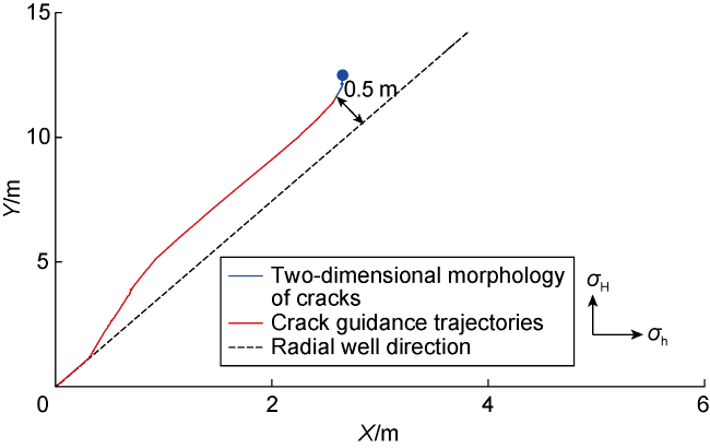
Fig. 6. Schematic diagram of deviation distances. |
It should be noted that the deviation distances is calculated from the two-dimensional fracture trajectory, while the simulation is derived from the radial borehole fracture, so the data of the radial borehole fracture need to be further processed. Firstly, the TECPLOT software is used to extract the data of two profiles in the radial borehole fracture, both of which pass through the axis of the single-story radial borehole and are perpendicular to the axis of the main wellbore, as shown in Fig. 7 . After that, the extracted two-dimensional fracture data is imported into the MATLAB software, and a program is written to calculate the deviation distances of the radial boreholes on the two profiles.
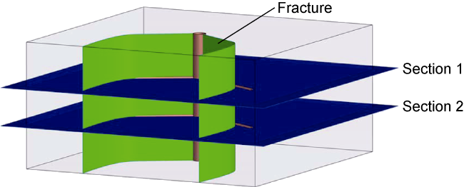
Fig. 7. Schematic diagram of fracture data extraction profile. |
2.2. Radial inter-well extrusion
Figs. 8 and 9 show the comparison of fracture geometries and deviation distances of synchronous fracturing (referred to as two radial boreholes fracturing) and one single radial borehole radial borehole fracturing (referred to as one single radial borehole fracturing) in the same layer. It can be seen from Fig. 8a that when the radial borehole is symmetrically distributed in the direction of the minimum horizontal stress, except for the azimuth of 2°, the fractures of the two radial boreholes fracturing under the other three azimuths deviate faster from the initial direction after propagation and gradually turn to the direction of the maximum horizontal stress. It can be seen from Fig. 9a that when the radial boreholes are symmetrically distributed in the direction of the minimum horizontal stress, the deviation distance of one single radial borehole fracturing under the four azimuths is greater than that of two radial boreholes fracturing.
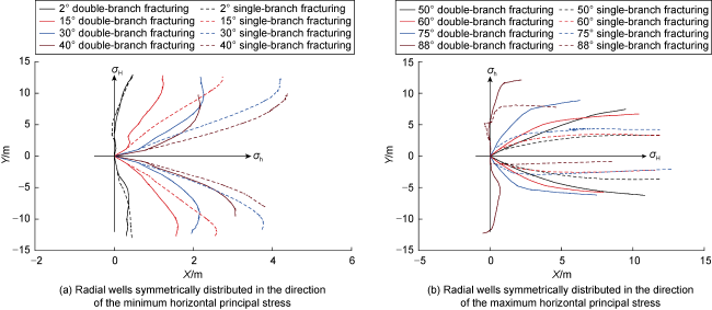
Fig. 8. Morphology comparison of two radial boreholes fracturing and one single radial borehole fracturing fractures. |
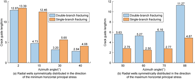
Fig. 9. Comparison of guide lengths of two radial boreholes fracturing and one single radial borehole fracturing fractures. |
It can be seen from Fig. 8b that when the radial borehole is symmetrically distributed in the direction of the maximum horizontal stress, the fractures of a single fracturing under the four azimuths deviate faster from the initial direction after propagation and gradually turn to the direction of the maximum horizontal stress. It can be seen from Fig. 9b that when the radial boreholes are symmetrically distributed along the direction of the maximum horizontal stress, the deviation distance of one single radial borehole fracturing under the four azimuths is smaller than that of two radial boreholes fracturing.
Comprehensive analysis of the above results shows that there is extrusion between radial boreholes during two radial boreholes fracturing, and when the radial boreholes are symmetrically distributed in the direction of the minimum horizontal stress, the extrusion effect will drive the fracture to deviate faster from the initial direction and reduce the deviation distances. When the radial borehole is symmetrically distributed in the direction of the maximum horizontal stress, under the action of the maximum horizontal stress, the fracture will deviate from the initial direction and gradually shift to the direction of the maximum horizontal stress. Due to the extrusion effect between the radial boreholes during two radial boreholes fracturing, part of the effect of the maximum level of principal stress will be counteracted, the deflection of the fracture will be delayed, and the length of the fracture guide will be increased.
To determine whether the extrusion originated from the interference of the radial borehole or the fracture on another fracture, the fracture propagation simulation of fracturing in the same layer of single radial borehole fracturing and single radial borehole injection fracturing fluid (referred to as single fracturing single injection fluid) is carried out. When a single fracturing is injected with a single fluid, in the two radial boreholes of the same layer, one radial borehole fracturing forms fractures, and the other radial borehole only injects fracturing fluid without fractures, and the liquid pressure in the two radial boreholes is equal. The fracture geometries of single fracturing and single fracturing with single injection are shown in Fig. 10 .
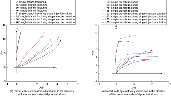
Fig. 10. Comparison of one single radial borehole fracturing and one single radial borehole fracturing one single radial borehole injection fracture geometries. |
It can be seen from Fig. 10a when fracturing one single radial borehole and injecting fluids into the other radial borehole, there is extrusion between radial boreholes, and when the radial boreholes are symmetrically distributed along the direction of the minimum horizontal stress, except for the azimuth of 2°, the extrusion pushes the facture to deviate faster from the initial direction with the other azimuths. It can be seen from Fig. 10b that when the radial boreholes are symmetrically distributed in the direction of the maximum horizontal stress, the extrusion effect between the radial boreholes under the fracturing method of single fracturing and single injection fluid injection can delay the deflection of the fracture.
The fracture geometries of two radial boreholes fracturing and one single radial borehole fracturing one single radial borehole injection are shown in Fig. 11 . There are differences in fracture geometries under the two fracturing methods, which indicate that in addition to the extrusion effect of the radial borehole on the fracture, there is also extrusion between the fractures during two radial boreholes fracturing.
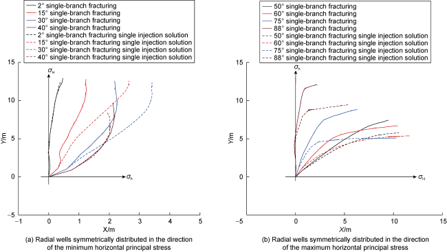
Fig. 11. Comparison of fracture geometries of two radial boreholes fracturing and one single radial borehole fracturing one single radial borehole injection solution. |
To analyze the effect of one radial borehole and its post-compression fractures on the deviation distances of the fracture fracturing of another radial borehole, the proportion of radial boreholes is defined. First, the absolute value of the difference between the deviation distances of single fracturing and single fracturing is calculated, and then the absolute value of the difference between the deviation distances of double fracturing and single fracturing is calculated, and the ratio of the two is the proportion of radial boreholes. The difference between the deviation distances of double fracturing, single fracturing, single fracturing and single fracturing at different azimuths and the radial borehole occupancy are shown in Fig. 12 . When the radial boreholes are symmetrically distributed along the direction of the maximum horizontal stress, the proportion of radial bore-holes under the other three azimuths is less than 50%, except for the azimuth of 88°, which indicates that the influence degree of fractures is higher than that of radial boreholes. When the azimuth is 88°, that is, when the distance of the two radial boreholes radial boreholes in the same layer is far, the influence of the radial borehole is more significant.
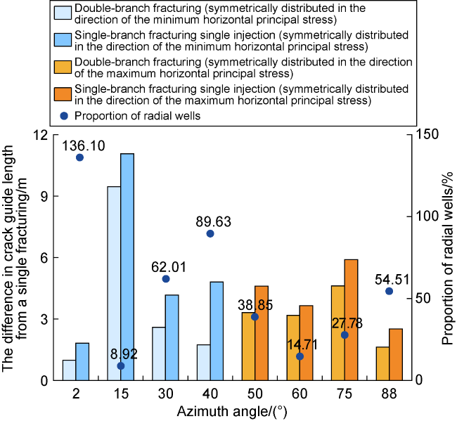
Fig. 12. The difference between the deviation distances and the proportion of radial boreholes in double fracturing, single fracturing, single fracturing and single fracturing. |
Based on the above analysis, when the two radial boreholes in the same layer is fractured, there is extrusion between the radial borehole under the synergistic effect of the radial borehole and the fracture. When the radial borehole is symmetrically distributed in the direction of the minimum horizontal stress and the azimuth is not less than 15°, the extrusion will reduce the deviation distances of the radial borehole. When the radial borehole is symmetrically distributed in the direction of the maximum horizontal stress, the extrusion will increase the deviation distances of the radial borehole.
Wu et al. [34] simulated the fracture geometries of sectional fracturing in horizontal wells by boundary element method. In the original stress field where the two horizontal principal stresses are equal, the two fractures propagate. If the fractures do not interfere with each other, the two fractures will continue to expand in the initial direction, and their trajectories should be straight, while the fractures in the simulation result are curved away from the initial direction after squeezing each other. Even if there is a difference between the maximum and minimum horizontal principal stresses in the original in-situ stress field, the fracture will deviate from the initial direction and gradually shift to the direction of the minimum horizontal stress. This further proves that when fracturing two radial boreholes in one layer, there is a squeeze effect between the radial boreholes, which drives the fracture to the direction of the minimum horizontal stress. This is corroborated by the extrusion effect proposed by the simulation results in this paper [34].
3. Influence law of fracture geometries
3.1. Effect of azimuth on deviation distances
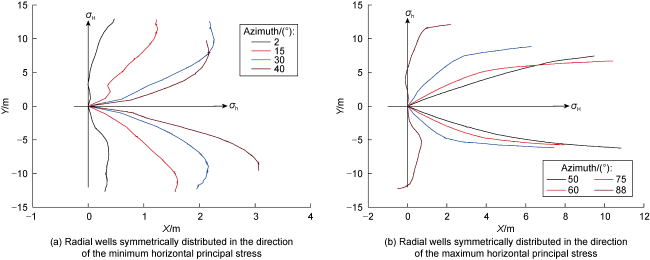
Fig. 13. Fracture geometries at different azimuths. |
It can be seen from Fig. 9 that when the radial borehole is symmetrically distributed in the direction of the minimum horizontal stress, with the increase of the azimuth, the deviation distance decreases, and the deviation distance at the azimuth of 2° is much larger than the deviation distance at azimuth 15°, 30° and 40°. When the radial borehole is symmetrically distributed in the direction of the maximum horizontal stress, the deviation distance first decreases and then increases with the increase of azimuth. It can be seen from Fig. 13b that when the azimuths are 50° and 60°, both fractures deviate from the initial direction and gradually turn to the direction of the maximum horizontal stress. When the azimuth are 75° and 88°, the fracture above the direction line of the maximum horizontal stress deviates from the initial direction and gradually turns to the direction of the minimum horizontal stress, and then gradually turns to the direction of the maximum horizontal stress. At an azimuth of 88°, the fracture propagation direction below the maximum horizontal stress direction line changed three times, which were the initial direction, the maximum horizontal stress direction, the minimum horizontal stress direction, and the maximum horizontal stress direction. When the azimuths are 75° and 88°, the fracture undergoes at least two turns, increasing the deviation distances. Therefore, the deviation distance of the radial borehole decreases first and then increases with the change of azimuth.
The fracture geometries are controlled by the control of the fracture by the radial borehole (which can be called the guiding effect), the extrusion between the radial boreholes, and the action of the maximum horizontal stress (which can be called the deflection effect), as shown in Fig. 14 . When the azimuths are 50° and 60°, the guiding effect of the radial borehole is strong, and the deflection effect together controls the fracture to turn slowly to the direction of the maximum horizontal stress after deviating from the initial direction. When the azimuths are 75° and 88°, the correction effect of the radial borehole is weak, under the action of extrusion, the fracture deviates from the initial direction and gradually turns to the direction of the minimum horizontal stress, and after extending a certain distance, under the action of deflection, the fracture direction changes again, and gradually turns to the direction of the maximum horizontal stress, so the fracture has more than 1 turn. When the azimuths are 2°, 15°, 30° and 40°, the guiding effect of the radial borehole weakens with the increase of azimuth, the extrusion effect increases with the increase of azimuth, and the extrusion is positively superimposed with the correction effect of the maximum horizontal stress, and the deviation distances decreases with the increase of azimuth under these three actions.
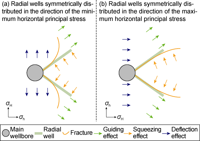
Fig. 14. Schematic diagram of three functions to jointly control fracture propagation. |
3.2. Effect of horizontal main pressure difference on deviation distances
Figs. 15 and 16 are respectively the fracture geometries and deviation distances under different levels of principal stress difference. When the radial borehole is symmetrically distributed in the direction of the minimum horizontal stress and the azimuth is 15°, the deviation distance first increases and then decreases with the decrease of the horizontal principal stress difference. The reason is that when the horizontal principal stress difference decreases from 10 MPa to 2 MPa, the deflection effect of the maximum horizontal stress on the fracture decreases, while the guiding effect of the radial borehole and the extrusion effect between the radial borehole remain stable, so the deviation distances increases. However, when the horizontal principal stress difference continues to drop to 0 MPa, the direction of the deflection action of the maximum horizontal stress changes, which in turn causes the fracture to gradually turn to the 45° direction. When the radial borehole is symmetrically distributed in the direction of the maximum horizontal stress and the azimuth is 75°, the deviation distance gradually increases with the decrease of the horizontal principal stress difference. Comparing the variation of deviation distances in radial boreholes when symmetrically distributed in the direction of minimum and maximum horizontal principal stress, it is found that the difference between the two is that after the horizontal principal stress difference decreases from 2 MPa to 0 MPa, the change trend of deviation distances is reversed. Overall, reducing the horizontal principal stress differential helps to improve the deviation distances of the radial borehole. When there is no horizontal principal stress difference, the induction effect of the radial borehole on the fracture can be fully exerted at the azimuth of 45°.
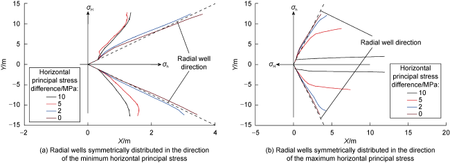
Fig. 15. Fracture geometries under principal stress difference at different levels. |
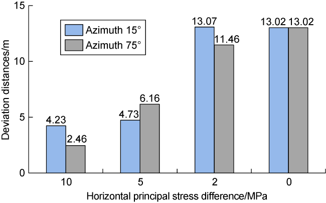
Fig. 16. Deviation distances under principal stress difference at different levels. |
3.3. Effect of rock matrix permeability on deviation distance
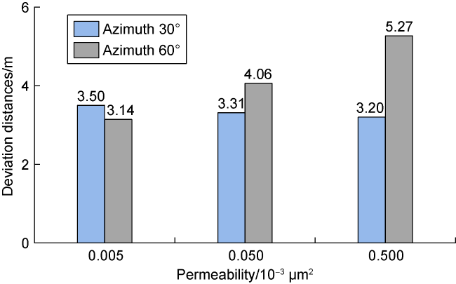
Figs. 17 and 18 are respectively fracture geometries and deviation distances under different rock matrix permeability. When the radial boreholes are symmetrically distributed in the direction of the minimum horizontal stress and the azimuth is 30°, the deviation distance slowly decreases with the increase of rock matrix permeability. When the radial boreholes are symmetrically distributed in the direction of the maximum horizontal stress and the azimuth is 60°, the deviation distance increases with the increase of rock matrix permeability. The reason is that the increase in rock matrix permeability will enhance the extrusion between radial boreholes. It can be seen from the model parameters that in order to converge the model calculation, the permeability of the radial borehole element is set to 2000 times the permeability of the matrix unit, and the permeability of the fracture element is equal to the permeability of the radial borehole element. Therefore, the greater the permeability of the rock matrix, the greater the fracture permeability, which reduces the flow resistance in the fracture, increases the average liquid pressure on the fracture surface, and finally enhances the extrusion effect, prompting the fracture to deviate from the initial direction faster. In addition, the increase of rock matrix permeability will enhance the guiding effect of radial boreholes. The reason is that the higher the permeability of the rock matrix, the greater the pore pressure of the matrix around the radial borehole, and the fractures are easily induced by the matrix with high pore pressure [35].
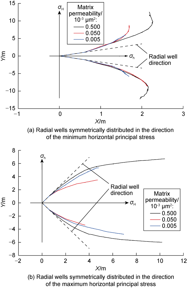
Fig. 17. Fracture geometries under different rock matrix permeability. |
Fig. 18. Deviation distances under different rock matrix permeability. |
When the radial boreholes are symmetrically distributed in the direction of the minimum horizontal stress and the azimuth is 30°, with the increase of the permeability of the rock matrix, the correction effect of the radial borehole and the extrusion effect between the radial boreholes are enhanced, but the negative superposition of the two is superimposed, and the reason for the slow decrease of the deviation distances is likely to be that the amplitude of extrusion is greater than that of correction.When the radial boreholes are symmetrically distributed in the direction of the maximum horizontal stress and the azimuth is 60°, with the increase of the permeability of the rock matrix, the guiding effect of the radial borehole and the extrusion effect between the radial boreholes are enhanced, and the two are positively superimposed, so the deviation distances increases.
4. Conclusions
When two radial boreholes in one layer are fractured, under the synergistic effects of the radial borehole and the fracture, there is extrusion between the radial borehole, which changes the propagation path of the fracture. Under the simulation conditions in this paper, when the radial borehole is symmetrically distributed in the direction of the minimum horizontal stress and the azimuth is greater than 15°, the deviation distance of the radial borehole is reduced by extrusion. When the radial boreholes are symmetrically distributed in the direction of the maximum horizontal stress, the extrusion increases the deviation distance of the radial borehole.
The fracture geometries are controlled by the rectification of a single radial borehole, the extrusion between radial boreholes in the same layer, and the deflection of the maximum horizontal principal stresses. When the radial borehole is symmetrically distributed in the direction of the minimum horizontal stress, the deviation distance of the radial borehole gradually decreases with the increase of the azimuth. When the radial borehole is symmetrically distributed in the direction of the maximum horizontal stress, the deviation distance of the radial borehole first decreases and then increases with the increase of the azimuth.
Under model assumptions, reducing the horizontal principal stress difference helps to improve the deviation distance of the radial borehole. Increasing the permeability of rock matrix can increase the pore pressure of the matrix around the radial borehole and enhance the induction effect of the radial borehole on fractures.
Based on the reservoir isotropy assumption, the radial borehole fracture propagation model of radial borehole fracturing of radial boreholes will be established considering reservoir heterogeneity.
Nomenclature
b—physical force vector within the entity, N/m3;
dβ,k—molecular diffusion coefficient of component k in liquid phase β, m2/s;
E—modulus of elasticity, Pa;
fβ,k—diffusion flow vector of component k in liquid phase β, kg/(m2·s);
Fk—mass flow vector of component k, kg/(m2·s);
Fk,adv—convective flow vector of component k, kg/(m2·s);
Fβ—mass flow vector of liquid phase β, kg/(m2·s);
g—gravitational acceleration vector, m/s2;
Gs—fracture surface energy, J;
h—normal load acting on the outer boundary Γh, Pa;
k—component number;
K—absolute permeability, m2;
KI,KII—fracture stress strength factors of types I and II, Pa·m1/2;
Krβ—relative permeability of liquid phase β;
Kd—distribution coefficient of liquid phase, m3/kg;
Mk—mass concentration of component k, kg/m3;
n—the normal vector of any tiny region dΓn on Γn, pointing inside Γn;
p—liquid pressure vector acting on the fracture surface, Pa;
pβ—fluid pressure of liquid phase β, Pa;
qk—point source and sink in Vn, kg/(m3·s);
rm—radius relative to the tip of the fracture in the local polar coordinate system, m;
S1—maximum horizontal principal stress component, MPa;
Sβ—saturation of liquid phase β, %;
sgn—unit modular function;
t—time, s;
t—tensile stress vector, Pa;
u—displacement field in a three-dimensional solid, m;
v—the unit normal vector of the outer boundary Γh;
Vn—any subregion of the fluid system, m3;
w—displacement difference vector between positive and negative sides of the local fracture surface, m;
X, Y—Cartesian coordinate system, m;
Xl,k—mass fraction of component k in liquid phase, %;
Xβ,k—mass fraction of component k in liquid phase β, %;
β—liquid phase number;
dΓ—any tiny face in a three-dimensional solid, m2;
γh—outer boundary of the three-dimensional solid, m2;
Γn—closed boundary enclosing Vn, m2;
Γs—fracture surface within a three-dimensional solid, m2;
ΔvI, ΔvII—the displacement of a point from the fracture tip rm (local polar coordinate system) at the fracture tip rm (local polar coordinate system) on types I and II fractures, m;
ε—linear strain, dimensionless;
θ0—fracture propagation angle, (°);
κ—Kolosov constant, for plane strain states, κ = 3-4υ;
μβ—viscosity of liquid phase β, Pa·s;
ρl—the density of the rock skeleton absorbing the liquid phase, kg/m3;
ρr—density of rock skeleton, kg/m3;
ρβ—density of liquid phase β, kg/m3;
σ—stress vector, Pa;
σh, σH—minimum and maximum horizontal principal stress, Pa;
τ0—dependence factor for porous media;
τβ—coefficient determined by phase saturation Sβ;
υ—Poisson's ratio;
ϕ—porosity of the flow system, %;
Ω—3D Solid, m3.