

Introduction
Sublacustrine fans are fan-shaped sedimentary bodies formed by gravity flows in deep-lake settings [1]. As the final sedimentary unit of a source-sink system, sublacustrine fans are abundant with organic matter and record paleoenvironmental information about the provenance area [2-3], which is important for hydrocarbon exploration, geological hazard assessment and climate prediction [4-5]. In recent years, the fundamental theory of gravity flows has developed rapidly, and novel causes of deep-water deposits such as hyperpycnal flow [6-7], bottom current [8], and hybrid event bed [9] have emerged successively. Compared with marine basins, freshwater lacustrine basins have lower water density, and are more susceptible to hyperpycnal flows under the actions of river-floods [6,10]. Therefore, the formation mechanism of sublacustrine fans is believed to be flood-generated hyperpycnal flows[10], rather than conventional comprehensions such as sandy debris flows [11-12].
Many scholars have created depositional models of sublacustrine fans in rifted basins, such as the Bohai Bay Basin [5,12], Beibuwan Basin [13], and Luanping Basin [14], based on trigger mechanisms, sedimentary process, and depositional products [5,12⇓⇓ -15]. Some studies investigated depositional architecture of sublacustrine fans dominated by sandy debris flows in rifted basins [5,13]. For sublacustrine fans of hyperpycnal flow genesis, the depositional architecture is understood insufficiently. Numerous research examples only revealed the types of sedimentary units [3,15], and the stacking patterns of deposits inside sublacustrine fans remain unknown. Moreover, the quantitative characterization and dimension of sublacustrine fans induced by hyperpycnal flows have been rarely reported. The differences in depositional architecture of sublacustrine fans within systems tracts are not understood [16⇓-18], which has exacerbated the contradiction between injection and production of sublacustrine fan reservoirs.
Here, taking the middle submember of the third member of Paleogene Shahejie Formation (Sha 3 Member) in the Shishen 100 area of the Dongying Sag in the Jiyang Depression of the Bohai Bay Basin as an example, the origin of sublacustrine fans and the spatial distribution of internal sedimentary units in the early stage of forced regression are investigated by using sequence stratigraphy, seismic sedimentology and depositional architecture anatomy. Then, the controls of the fourth-order base-level changes on the depositional architecture of sublacustrine fans of hyperpycnal flow genesis are discussed. The study results are practically significant for well pattern deployment and adjustment to develop sublacustrine fan reservoirs.
1. Geological setting
A first-order tectonic unit called the Jiyang Depression can be found in the Bohai Bay Basin in eastern China. The Dongying Sag is a half graben-like lacustrine rift basin in the southern part of the Jiyang Depression, and it can be divided into: steep slope zone (the Zhengjia-Yanjia steep slope), central anticline zone, gentle slope zone (the Jinjia-Liuqiao gentle slope and the North Guangrao gentle slope), Lijin, Minfeng, Niuzhuang and Boxing subsags [5,17] (Fig. 1a ). The Shishen 100 area rests structurally in the western part of the central anticline zone, and plunges westward into the Lijin subsag. The study area, approximately 30 km2, has 280 development wells, 10 cored wells, and full 3D seismic coverage, which provide a wealth of data to the analysis of depositional architecture of sublacustrine fans.

Fig. 1. Division of tectonic units and sequence stratigraphic framework of Shahejie Formation in Dongying Sag. LST—lowstand systems tract; TST—transgressive systems tract; HST—highstand systems tract; FSST—falling stage systems tract. |
The Paleogene in the study area consists of the Kongdian Formation, the Shahejie Formation and the Dongying Formation. The Shahejie Formation is split into four members from bottom to top, and the third member or Sha 3 Member is subdivided into the lower, middle and upper submembers (Fig. 1b ). This study deals with the middle submember of the Sha 3 Member (Middle Sha 3 Member), which is 300-1200 m thick and mainly composed of thick gray and dark-gray mudstones intercalated with thin sandstones.
During the deposition of the Middle Sha 3 Member, the Dongying Sag was in a subtropical warm and humid climate with ample rainfall, which provoked a significant expansion of the lake basin and a reduction in the salinity of lake water. There are numerous deltaic systems in the gentle slope zone. Typically, the Dongying delta has the largest growth area and the longest depositional period, and progrades to the Minfeng and Lijin subsags [17]. It is the major contributor of sediment supply in the Shishen 100 area [12]. During the late deposition of the Middle Sha 3 Member, the Dongying delta rapidly prograded into the lake basin, and sediments in the delta slope were prone to collapse and form mass-transport complexes. Meanwhile, seasonal floods easily triggered hyperpycnal flows in freshwater lake basin, which directly passed the shore-shallow lake area and eventually deposited in the study area [17-18].
2. Fourth-order base-level changes
The Paleogene in the study area, entirely in the rifting stage, can be divided into four rifting episodes: I, II, III and IV [17]. Based on the background of tectonic and sedimentary evolution in the Bohai Bay Basin, most scholars subdivided Episode III into three third-order sequences [17]: ESQ1, ESQ2 and ESQ3 (Fig. 1b ). On this basis, this paper divides the fourth-order sequences.
2.1. Fourth-order sequence division
The top and bottom of the Middle Sha 3 Member in the Dongying Sag correspond to the seismic reflectors T4 and T6, respectively (Fig. 1b ), above and below which truncation and onlap terminations can be seen (Fig. 2a ). Therefore, T4 and T6 are regarded as boundaries of ESQ2. The sequence division scheme in this study adopts a four-tract stratigraphic model, which can be closely related to base-level changes. The upper portion of ESQ2 exhibits numerous high-angle progradational reflections that possess well-preserved topsets, indicative of the highstand systems tract (HST) (Fig. 2a ). Above the HST, there are several sets of progradational events without topsets, which are in unconformity contact with T4 and overlapped toward the lake basin center, responding to a falling stage systems tract (FSST). Highstand foresets are downlapped above seismic events with a stable distribution of thickness in the whole area. These events appear as a sub-parallel reflected structure, and exhibit high values on the spontaneous potential (SP) log (Fig. 2b ), corresponding to a large set of fine-grained sediments, and thus interpreted as a transgressive systems tract (TST). However, the spatial distribution of the lowstand systems tract (LST) is bounded to the downdropped block of the fault-slope break zone (Fig. 2a ).
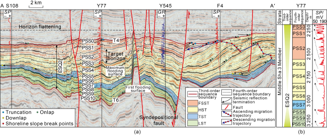
Fig. 2. Interpretation of fourth-order sequence of ESQ2 in Middle Sha 3 Member of Well Y77 in Dongying Sag (section location shown in |
Coupling well data with seismic data, the fourth-order sequences in the study area are divided (Fig. 2b ). Four fourth-order sequences (PSS3-PSS6) of the HST and three fourth-order sequences (PSS0-PSS2) of the FSST in Well Y77 are shown as progradational deposits with increasing sand content on the SP log. Furthermore, the above-mentioned seven fourth-order sequences have obvious boundaries based on the recognition of seismic reflection terminations including onlap, toplap and truncation (Fig. 2a ). In contrast, three fourth-order sequences (PSS8-PSS10) of the LST appear to onlap sequentially along the bottom boundary of T6.
Shoreline migration trajectories record the vertical and lateral migration positions of shoreline slope break points in different periods, and can be used to invert the evolution history of base-level changes [19]. Shoreline migration trajectories from PSS6 to PSS3 are ascending (Fig. 2a ), meaning that slope break points migrated upward and toward the basin center [19], resulting from the long-term rise of the third-order base-level in highstand normal regression (Fig. 3a ). However, the descending trajectories in PSS2-PSS0 are characterized by obvious downward and basinward migration of shoreline trajectories [19] (Fig. 2a ), which were formed by the rapid fall of the third-order base-level during forced regression (Fig. 3a ).
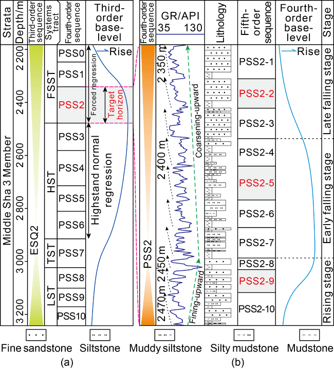
Fig. 3. (a) Third-order base-level changes in ESQ2 and (b) division of fifth-order sequence and fourth-order base-level changes in PSS2 of Well Y545. |
2.2. Fourth-order base-level changes within PSS2
According to a relatively mature hierarchical classification of depositional architecture of sublacustrine fan systems established in previous studies [20], it is believed that channel or lobe complexes that constitute a sublacustrine fan correspond to the parasequence hierarchical orders. In this study, interface identification markers such as stable mudstones and high values of gamma ray (GR) log are used to subdivide PSS2 into ten fifth-order sequences, namely PSS2-10 to PSS2-1, from bottom to top (Fig. 3b ). PSS2-10 to PSS2-8 reflect the overall trend of upward-fining, corresponding to the rising stage of the fourth-order base-level [21]. However, PSS2-7 to PSS2-1 represent the opposite change process, which formed in the falling stage of the fourth-order base-level [21]. According to the analysis in the preceding section, PSS2 was deposited in the early stage of forced regression of the third-order sequence. Based on the composite principle of different hierarchies of base-level, the rising stage of the fourth-order base-level was easily inhibited by the falling stage of the third-order base-level. Also, the early researches used the geochemical analysis data such as trace elements to confirm that PSS2 was in a paleoclimate ranging from semi-humid to arid condition[18]. Arid climate may cause evaporation of lake water to be greater than precipitation, so the whole PSS2 was dominated by falling process of the fourth-order base-level (Fig. 3b ). Using sand-to-mud ratio and grain-size of sandstones, the long-term falling process is divided into the early and late stages. To anatomize the architecture of the sublacustrine fans, PSS2-9, PSS2-5 and PSS2-2 are selected to represent the rising stage, early falling stage and late falling stage of the four-order base-level, respectively.
3. Sedimentary characteristics and sandbody distribution of sublacustrine fans
3.1. Lithofacies associations
Based on the data of approximately 420 m cores from the study area, and according to the characteristics of color, grain-size, texture and sedimentary structure, nine types of gravity flow sandstone lithofacies were identified (Fig. 4 , Table 1 ), and the flow properties and transport mechanisms of lithofacies were analyzed. In terms of vertical stacking patterns of lithofacies and the contact relationship with deep-lake dark mudstones, six lithofacies associations (LA1 to LA6) were determined (Fig. 5 ).
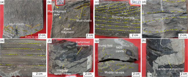
Fig. 4. Typical core photos of gravity flow sandstones in PSS2. (a) Well S102, 3291.26 m, clean massive fine sandstone (S3) in the upper part and massive fine sandstone with imbricated mud-clasts (S2) in the lower part, where mud-clasts are arranged in imbricate form and close to the scoured surface; (b) Well S103, 3294.25 m, massive fine sandstone with floating clasts (S4), layered plant fragments visible on top; (c) Well S106, 3411.67 m, fine sandstone with cross-bedding (S1) and fine sandstone with parallel bedding (S6), separated by scoured surfaces; (d) Well S102, 3287.24 m, siltstone with ripple bedding (S7); (e) Well S102, 3290.55 m, muddy siltstone with horizontal bedding (S8); (f) Well S3-12-12, 3165.82 m, sandstone with deformed bedding (S9), with deformed mudstone and irregular sandy mass; (g) Well S3-12-12, 3163.60 m, massive fine sandstone with muddy rip-ups (S5); (h) Well S3-12-12, 3166.89 m, sandstone with deformed bedding (S9), with sandstone injections. |
Table 1. Lithofacies classification of gravity flow deposits in the study area |
| Lithofacies | Depositional features | Sedimentary process | Origin |
|---|---|---|---|
| Fine sandstone with cross-bedding (S1) | Cross-bedding, sometimes with a little plant fragments and muddy rip-ups at the bottom | Bed-load transport [6-7] | Quasi-steady high-density turbidity current [10,22] |
| Massive fine sandstone with imbricated mud- clasts (S2) | Low mud content, a little muddy rip-ups at the bottom distributed along the bedding, and the inner reddish mud clasts arranged in imbricated formation along scoured surface | Bed-load transport [6-7], traction carpet [9] | Quasi-steady high-density turbidity current [10,22], high-density turbidity current [9] |
| Clean massive fine sandstone (S3) | Low mud content, massive texture, sometimes with abundant plant fragments | Traction carpet [9] | High-density turbidity current [9] |
| Massive fine sandstone with floating clasts (S4) | Massive structure, a small amount of reddish mud clasts and muddy rip-ups, with intermittent horizontally distributed plant fragment layer on the top | Traction carpet [9] | High-density turbidity current [9] |
| Massive fine sandstone with muddy rip-ups (S5) | Massive structure, a large number of dark mud clasts and sub-vertical muddy rip-ups | Mass transport [9,11,23] | Sandy debris flow [9,11,23] |
| Fine sandstone with parallel bedding (S6) | Parallel bedding | Traction carpet [9], suspended-load transport [6-7,9 -10,24] | High-density turbidity current [9], low-density turbidity current [9] |
| Siltstone with ripple bedding (S7) | Ripple cross-bedding, with muddy laminae | Suspended-load transport [6-7,9 -10,24] | Low-density turbidity current [9] |
| Muddy siltstone with horizontal bedding (S8) | Horizontal bedding, with muddy laminae | Suspended-load transport [6-7,9 -10,24] | Low-density turbidity current [9] |
| Sandstone with deformed bedding (S9) | Deformed bedding, convolute bedding and sandstone injection | Mass transport [9,11,23] | Slump [9,11,23] |
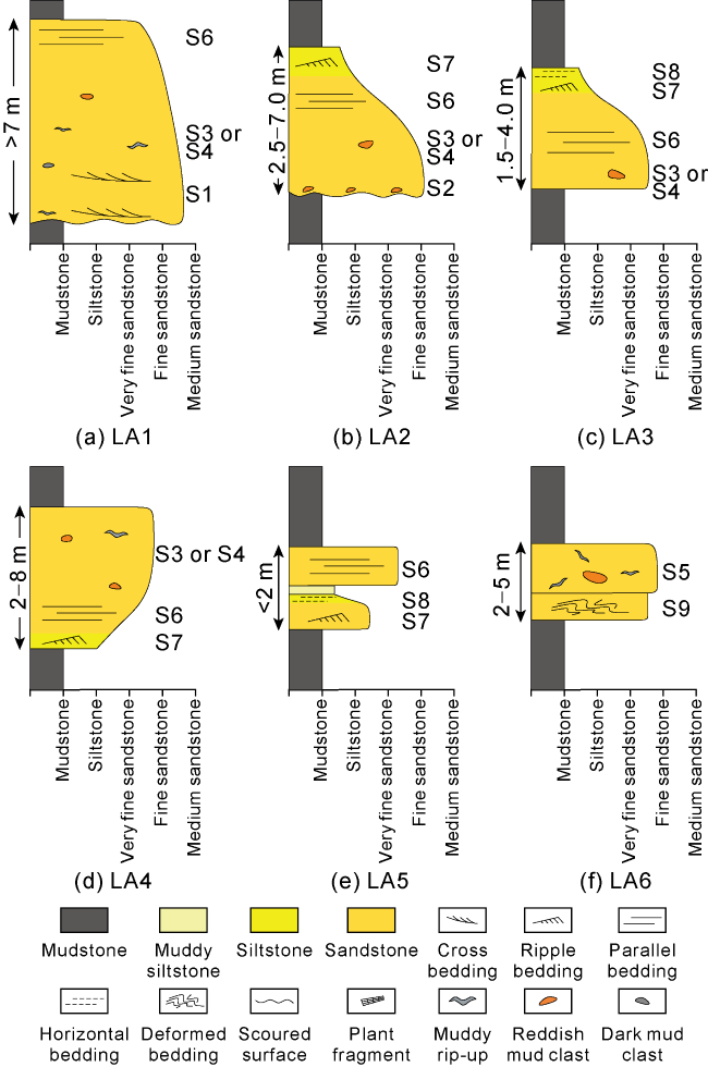
Fig. 5. Pattern of lithofacies associations of gravity flow in the study area. |
Lithofacies association 1 (LA1) is composed of S1 and S3, or S4 and S6 (Fig. 5a ), which has obvious erosion at the base. The thickness proportion of S1 in LA1 is relatively high, generally 30%-60%. LA1 is interpreted as the products of quasi-steady high-density turbidity currents [10,22]. The continuous shearing and dragging of high-concentration sediments at the bottom by the overlying passing turbulent flow were likely to form a traction structure [6-7]. The coexistence of massive sandstones and sandstones with parallel bedding in the upper part of LA1 is related to the repeated collapse of traction carpets beneath the high-density turbidity currents [9]. Erosive surface at the base of LA1 and a large set of bed-load deposits in the lower part of LA1 together indicate high-energy flow property [6]. Therefore, LA1 might have formed in depositional environment of the proximal channel.
Lithofacies association 2 (LA2) consists of a fining-upward succession of S2 and S3, or S4, S6 and S7 (Fig. 5b ). There is also an erosive surface at the base of LA2. But compared with LA1, suspended-load facies S7 is developed at the top of LA2, and the total thickness of LA2 is reduced. LA2 is composed of high-density turbidity current deposits (S2 and S3, or S4 and S6) and low-density turbidity current deposits (S7). Considering that S7 at the top of LA2 indicates a decrease in flow energy [6], LA2 might have evolved downstream of LA1.
Lithofacies association 3 (LA3) consists of S3, or S4, S6, S7 and S8, from bottom to top (Fig. 5c ), which has no erosive sign at the base, and an abrupt contact with the underlying dark mudstone. LA3 is primarily composed of low-density turbidity current deposits, and its overall performance is the classic Bouma sequence, which originated during the waning phase of flow energy [9]. This association is often associated with LA2 and lacks an erosive surface at the base, and might have grown in depositional environment of the distal channel flank.
Lithofacies association 4 (LA4) is characterized by S7, S6 and S3, or S4 from bottom to top (Fig. 5d ). Sometimes, S6 or S7 is missing at the bottom, showing a coarsening-upward succession as a whole. LA4 is mainly composed of low-density turbidity current deposits of suspended-load origin, and S7-S6 reflects the energy waxing phase in the initial stage of flood [6]. This association with coarsening and thickening upward succession usually indicates depositional environment of the distal lobe [25].
Lithofacies association 5 (LA5) is produced in the form of thin interbeds from S6, S7 and S8 (Fig. 5e ), which is the products of low-density turbidity currents in a full turbulent flow regime [24]. Vertical stackings of different sedimentary structures of flow genesis in LA5 reflect the constant changes in flow hydrodynamic conditions [6], together with thin layers of fine-grained sediments, indicating a marginal gravity flow depositional environment [18].
Lithofacies association 6 (LA6) is composed of S9 and S5 from bottom to top (Fig. 5f ). The lower part of LA6 is slump deposits formed by sediment collapse, and the upper part is sandy debris flow deposits. They reflect flow transformation from slumps to sandy debris flows vertically [5].
3.2. Types and characteristics of sedimentary units
Based on the analysis of lithofacies associations (Figs. 4 and 5 ), it is considered that sedimentary systems of sublacustrine fans occurred during the deposition of PSS2. Referring to the depositional models of lobes at channel mouths [20,25] and mass-transports [23], six types of sedimentary units were identified in the study area, namely main channel, distributary channel, lobe, lobe fringe, tongue, and inter-channel/lobe (equivalent to third-order tectonic units or individual channel/individual lobe [20]) (Fig. 6 ).
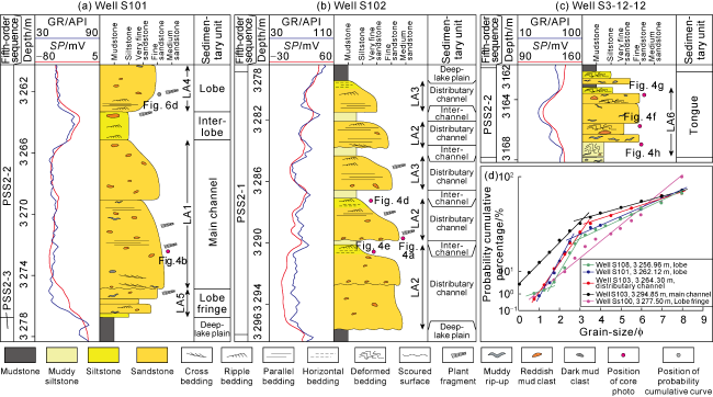
Fig. 6. Sedimentary sequences and grain-size probability cumulative curves of sedimentary units in the study area. GR—gamma ray; SP—spontaneous potential. |
Main channels are distributed in the inner fan, which are the feeder conduits for sediments in sublacustrine fan and the main depositional place for gravity flow [25]. Main channel is composed of LA1 on the sedimentary section (Fig. 6a ), with erosive characteristics observed at the base (Fig. 4c ). The grain-size probability curve of main channel deposit shows mainly two segments, with the saltation population accounting for 85% (Fig. 6d ), which reflects a bed-load dominated sedimentary process. Main channel deposits exhibit a homogeneous rhythm in the vertical direction (Fig. 6a ), with the thickness of generally 7-14 m. The GR log is characterized by a very thick box-shaped response.
Distributary channels are formed by main channels extending and bifurcating downstream during the waning stage of flow energy, and serves as a source transportation hub to deliver sediments to the distal lobes [20]. Two types of lithofacies associations are built on the sedimentary section (Fig. 6b ): LA2 is produced near the center of distributary channels, while LA3 is formed on the sides of distributary channels. Distributary channel deposit possesses a fining-upward succession in the vertical direction, with a thickness of 2.5-7.0 m in general, and its GR log shows a low-amplitude bell-shape (Fig. 6b ). The grain-size probability curve of distributary channel sandbodies is also mainly two segments, with the proportion of saltation population lower than that of main channels, but still reaching 70%-80% (Fig. 6d ).
Lobes are the fan deposits formed by gravity flows at the end of distributary channels without constraints of the topography, which rapidly spread and decelerated to the surroundings in a relatively open environment [25]. Lobe is produced as LA4 on the sedimentary section (Fig. 6a ), and its GR log presents as funnel-shape with low-medium amplitude. The thickness of lobe is generally 2-8 m. The grain-size probability curves of lobe sandbodies have two or three segments (Fig. 6d ), with the proportion of suspension population significantly higher than that of channel sandbodies, reaching 40%-50%.
Lobe fringes, the most distant depositional environment of the sublacustrine fans, are distributed on the side or front of lobes [25], and composed of LA5 on the sedimentary section (Fig. 6a ). Lobe fringe sandbodies show a coarsening-upward succession or no obvious rhythm changes in the vertical direction. The GR logs are finger-shaped with medium-high amplitude. The grain-size probability curve is one segment with a high slope (Fig. 6d ), indicating a sedimentary process dominated by suspended-load transport.
Tongues are generated by multi-stage superimposed tongue-like deposits attributed to overall unloading and freezing deposition of the low-energy slumps and debris flows [23]. Tongues are produced as LA6 on the sedimentary section (Fig. 6c ), and vertically present coarsening-upward succession or no obvious rhythm features. The thickness of tongues is generally 2-5 m, and the GR logs are funnel-shaped with medium amplitude.
Inter-channels/lobes are created on in-situ deposits of normal deep-lake or diluted low-density turbidity current [9], and composed of massive mudstones and silty mudstones, representing a low-energy depositional environment. They exhibit no obvious rhythmic changes in the vertical direction, and the GR logs display a high-amplitude tooth-shape (Fig. 6b ).
3.3. Distribution of sublacustrine fan sandbodies
In the Shishen 100 area, wells are primarily located between the Liang 11 and He 91 faults (Fig. 7 ), but scarce in the northern part. In this study, the method of seismic sedimentology was used to accurately predict the plane distribution of gravity flow sandbodies [18]. The seismic data in the Middle Sha 3 Member in the study area reflect the main frequency of about 30.5 Hz, and the maximum vertical resolution of about 20 m. The maximum thickness of a single sand layer interpreted by logging is about 15 m. Therefore, the seismic wavelet frequency was divided into five central frequencies (10-50 Hz, with an interval of 10 Hz), and then each data volume of frequency decomposition was converted into a lithology data volume by 90° phase shift. The 30 Hz data volume was discovered to accurately identify thin gravity flow sandstones, the majority of which correspond to troughs on the seismic section (Fig. 7a ). Taking the fourth-order sequence boundaries as the isochronous constraint interfaces [18], the amplitude stratal slices were extracted along fifth-order sequence boundaries. By calibrating the amplitude stratal slices and lithologies of cored wells, it is found that the yellow and dark green areas on the slices correspond to gravity flow sandstones, whereas the light green area indicates sand-mud transitional deposits. On this basis, the boundaries of gravity flow sandbodies were delineated (Fig. 7b ).
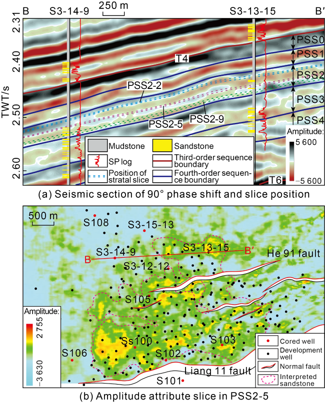
Fig. 7. 90° phase-shifted seismic section and amplitude attribute slice in the study area. |
Under the constraints of sandbody boundaries, combined with the results of sandstone logging interpretation of development wells, the sandbody thickness map of fifth-order sequences was constructed. Sandbodies in PSS2-9 spread in the form of highly channelized dendritic fan (Fig. 8a ). The channel-like sandbodies in the inner fan have the largest thickness and lateral scale; they are then bifurcated into multiple secondary channel-like sandbodies in the middle fan, and finally all evolve into sheet- like sandbodies in the outer fan. Dendritic fan-shaped sandbodies are also developed in PSS2-5, with smaller distribution than that in PSS2-9, as the lateral scale and extension distance of internal channel-like sandbodies (Fig. 8b ). The distribution of sandbodies in PSS2-2 is significantly different from that in the previous two stages. At this stage, the distribution range of dendritic fans shrinks further. The inner channel-like sandbodies extend a relatively short distance, and quickly transforms into sheet- like sandbodies. In addition, there are many small isolated tongue-like sandbodies around the dendritic fans (Fig. 8c ).
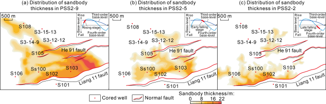
Fig. 8. Sandbody thickness distribution of fifth-order sequences in the study area during PSS2. |
Based on a thorough analysis of sedimentary characteristics and logging responses of sedimentary units in the cored wells, sedimentary units were identified and divided in all development wells. Then, the distribution of dominant microfacies in fifth-order sequences (equivalent to fourth-order tectonic units or channel/lobe complexes [20], consisting of individual channels/lobes formed in different stages) was finally determined in conjunction with the distribution of sandbodies. From PSS2-9 to PSS2-2, the extension distances of channel complexes in the study area reduce gradually, and the distribution range of channel complexes and lobe complexes decreases. Moreover, multi-branched tongue complexes are also developed in PSS2-2 (Fig. 9 ).
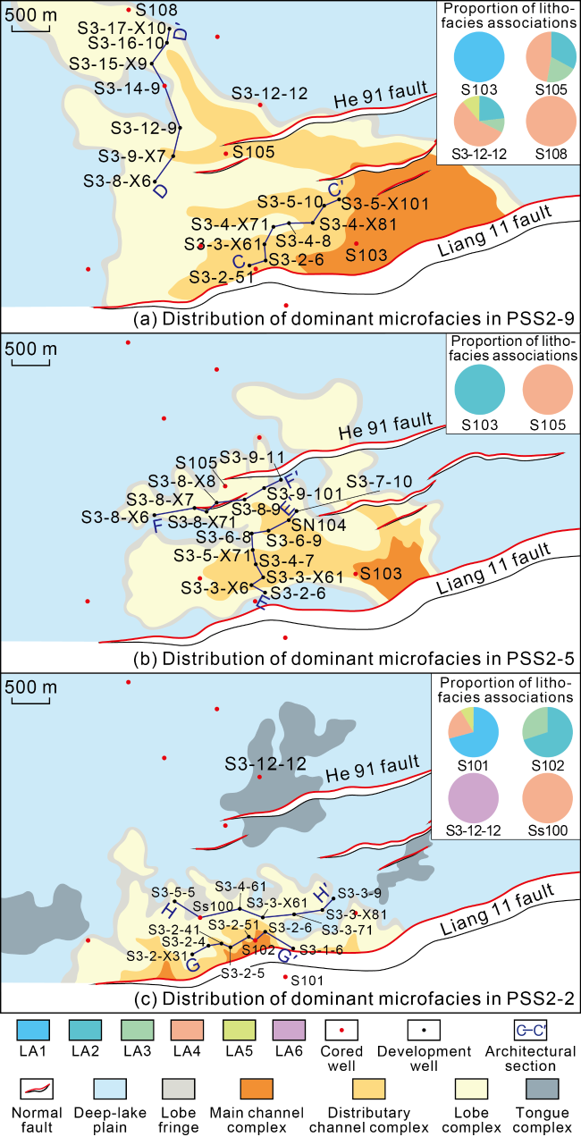
Fig. 9. Dominant sedimentary microfacies and thickness proportion of lithofacies associations of cored wells during PSS2 in the study area. |
4. Depositional architecture of sublacustrine fans
4.1. Differences in depositional architectures of channel and lobe complexes in the same stage
Sedimentary architecture refers to the morphology, scale and stacking relationship of different levels of configuration units [20]. The branched lake-bottom fan in the study area is mainly composed of channel complexes and lobe complexes. To analyze the depositional architectural differences between channel complexes and lobe complexes, the flattening of mudstone marker layers at top or bottom, elevation differences and lateral thickness variations of sandbodies [16] were used for correlation of sedimentary architecture units. Taking dendritic sublacustrine fans in PSS2-9 as an example, multi-branched distributary channel complexes are developed in the middle fan, and deeply incised the muddy basement, forming a shape with a flat top and a convex bottom (Fig. 10a ). Lobe complexes on both sides of channels are in the shape of a flat bottom and a convex top, and their formation process may be related to the flow relaxation mechanism [26]. When the channel grew downstream, gravity flows left the channel mouths and lost their restriction, resulting in an increase in the lateral pressure gradient and bed shear velocity at the bottom of flows, thereby generating a scour field at channel mouths [26], and sedimentation occurred on both sides of channels to form dike-like lobes. In the outer fan, the hydrodynamic force of distributary channels weakened rapidly, and the incised depth gradually became shallower. Distributary channels are only distributed in the middle and upper parts of lobe units, and together form channel-lobe complexes. The thickness of lobe complexes at the terminal of channels is relatively small, which also hold a flat bottom and a convex top (Figs. 9a and 10b).
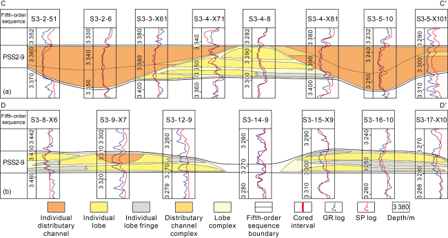
Fig. 10. Architectural profile of channel and lobe in dendritic sublacustrine fans at the rising stage (PSS2-9) of fourth-order base-level (see |
4.2. Sedimentary architectural differences in sublacustrine fans in different stages
In PSS2-9, individual distributary channels formed in different stages were unlikely to migrate laterally. Meanwhile, the late individual channel deeply incised into the early individual channel vertically (Fig. 10a ), resulting in a cut-and-fill architectural pattern [27]. Lobes of multiple periods in the outer fan migrated in a non-directional manner, producing a lateral swing type of compensational stacking pattern [20] (Fig. 10b ). In PSS2-5, individual distributary channels in each phase exhibit indistinctive unidirectional migration laterally and superposed stacking vertically [27], demonstrating that the late channel shallowly incised the early channel (Fig. 11a ). The outer fan lobe is characterized by the lateral migration type of compensational stacking pattern [20] (Fig. 11b ). Compared to PSS2-9, the incision ability and lateral scale of an individual channel in PSS2-5 are diminished. In PSS2-2, individual distributary channels of various stages migrated obviously laterally, which represent an isolated stacking vertically [27] (Fig. 12a ), indicating that the late channels did not incise and erode the early channels and stable muddy interlayers were preserved between individual channels. However, the multi-period individual lobes in the outer fan constituted an aggradational stacking pattern [20] (Fig. 12b ).
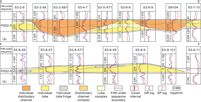
Fig. 11. Architectural profile of channel and lobe in dendritic sublacustrine fans at the early falling stage (PSS2-5) of fourth-order base-level (see |
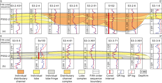
Fig. 12. Architectural profile of channel and lobe in dendritic sublacustrine fans at the late falling stage (PSS2-2) of fourth-order base-level (see |
4.3. Dimensions of sublacustrine fans
With the aid of the results of sedimentary unit distributions and architectural anatomies, quantitative parameters of dendritic sublacustrine fans, channels and lobes in different periods of PSS2 were counted. The results show that individual channels have opposite trends in width variation to individual lobes, which can be divided into three stages (Fig. 13a -13b). In the rising stage of the fourth-order base-level, individual channels display the largest lateral scale, with a width of 710-1623 m, while individual lobes have the smallest lateral scale, with a width of only 629-874 m. In the early falling stage of fourth-order base-level, the lateral scales of individual channels and lobes are moderate, with widths of 423-684 m and 773-1024 m, respectively. In the late falling stage of fourth-order base-level, the lateral scale of individual channels is the smallest, with a width of only 326-580 m, whereas the lateral scale of individual lobes is the largest, with a width of 1014-1655 m. In addition, from the rising stage to the late falling stage of the fourth-order base-level, the distribution range of dendritic sublacustrine fans gradually shrank, with the sedimentary area decreasing from 13.64 km2 to 4.97 km2 (Fig. 13c ), and the width-to-length ratio increasing from 0.51 to 2.8 (Fig. 13d ); the maximum length of channel complexes inside sublacustrine fans decreased from 4.92 km to 0.73 km (Fig. 13e ), and the ratio of channel-to-lobe decreased from 1.13 to 0.28 (Fig. 13f ).
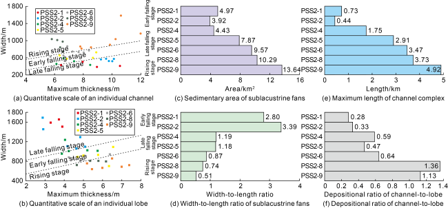
Fig. 13. Quantitative characterization parameters of dendritic sublacustrine fans at different stages. |
5. Discussion
5.1. Trigger mechanisms of sublacustrine fans formed by gravity flows in the early stage of forced regression
Triggering mechanisms and development principles of deep-water gravity flows have always been the focus of sedimentology [11⇓⇓⇓-15]. At present, most scholars believe that the gravity flow deposition in forced regression is mainly produced by sediment collapse caused by the instability of delta slope [17-18,21,28]. This study, using evidence such as sedimentary structures, lithofacies associations, and grain- size probability cumulative curves, confirms that sublacustrine fans in the early stage of forced regression were dominantly originated from hyperpycnal flow caused by sustained supply from river-floods [6-7], followed by sediment re-transport triggered by sediment collapse [5,13].
Firstly, hyperpycnal flow known as the quasi-steady turbidity current can endure for several days to several weeks [22]. Lithofacies S1 and S7 were usually formed in long-term ripple or dune stability fields [9,24] (Fig. 4c -4d), indicating hyperpycnal flow properties of sustained flood recharge [6-7]. In lithofacies S2, the imbricate arrangement of well-rounded, uniform-sized mud clasts along the scoured surface (Fig. 4a ) suggests the selective transport of overlying passing turbidity currents [6] and long-term shear dragging [6-7]. Secondly, a large amount of brown- red mud clasts and plant fragments in lithofacies S4 are usually terrigenous debris transported directly from extra-basin by floods [7] (Fig. 4b ). Furthermore, lacustrine hyperpycnal flow sandbodies are mainly composed of bed-load and suspended-load deposits [6,28]. In the study area, the grain-size probability curves of gravity flow sandstones in dendritic sublacustrine fans are mainly two-segments and three-segments (Fig. 6d ), with the saltation population accounting for 70% to 85%, reflecting traction currents of bed-load transport. On the other hand, the layered plant fragments at the top of S4 (Fig. 4b ) were formed by the rapid sedimentary process of suspended-load transport [6-7]. Dendritic sublacustrine fans are composed of LA1 to LA5 from near to far (Fig. 9 ), showing that the energy of hyperpycnal flow declines slowly. In other words, the quasi-steady high-density turbidity currents in the proximal setting were unloaded continuously from bed-load transport and transited to the low- density turbidity current deposits dominated by suspended- load transport in the distal setting. Finally, the formation of gravity flow channels in lacustrine basins is related to hyperpycnal flow, with the bed-load transport highly capable of eroding mudstone basement [7,28] (Fig. 4a and 4c). Therefore, the above evidences prove that the sandbodies of dendritic sublacustrine fans in various stages of PSS2 in the early stage of forced regression are originated from hyperpycnal flow triggered by river-floods.
In the late falling stage of fourth-order base-level, the cored well S3-12-12 was located at the edge of the isolated tongue complex (Fig. 9c ). Slump folds (Fig. 4g ), sandstone injections (Fig. 4h ) and other sedimentary deformed structures can be seen on the cores, which were formed in the process of sediment re-transport [5,11,23]. Irregular muddy rip-ups in lithofacies S5 are sub-vertically arranged (Fig. 4g ), indicating the plastic rheological nature of debris flow deposits [5]. LA6 also reflects flow transformation from slumps into sandy debris flows [23]. These evidences reveal that a small amount of sublacustrine fan deposits were triggered by sediment collapse in the early stage of forced regression.
5.2. Control of fourth-order base-level changes on the planar morphology of sublacustrine fans
The fourth-order base-level controls the properties of gravity flow in the study area as the main extra-basin factor [28-29], while micro-geomorphology affects flow transport process as the subordinate internal basin factor [28,30], which jointly determine the plane distribution characteristics of sublacustrine fans.
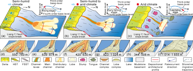
Paleoclimate is the primary driver for high-frequency base-level changes in lacustrine basins [31]. In PSS2, the short-term fourth-order base-level rise correlated to a humid climate [18], whereas the long-term fourth-order base-level fall corresponded to an arid climate [18]. Under arid climate conditions, the source area contained less vegetation coverage, and mechanical weathering occurred frequently, increasing the yield of coarse-grained debris. However, chemical weathering was more likely to appear under humid climate conditions, resulting in more fine-grained debris [2]. During the fourth-order base-level fall, the accommodation in the delta front area gradually decreased, and coarse-grained debris were easily transported over the delta and into the deep-lake settings [21]. Therefore, the corresponding paleoclimate became drier from rising to falling of the fourth-order base-level, flow volume and mud content of extra-basin sediments carried by hyperpycnal flows were both reduced, which together led to a decrease in flow efficiency and the maximum transport distance of hyperpycnal flows [29]. As a result, the plane morphology of sublacustrine fans of hyperpycnal flow genesis changed from a significantly channelized fan to a skirt-like fan (Figs. 8 and 9 ), and the width-to-length ratio gradually increased (Fig. 13d ).
The fall of the fourth-order base-level in PSS2 was strengthened by synergistic effect of the third-order base-level fall, and then the Dongying Delta prograded rapidly toward the lake basin center [18], making the unconsolidated deposits in the delta front slope more likely to collapse. A large number of slumps and sandy debris flows entered the study area, and frozen deposition occurred near the slope break zone of the Liang 11 fault [5,23], forming isolated tongue complexes (Fig. 9c ). The relatively arid paleoclimate during the late base-level fall led to a decrease in the frequency and sediment volume of river-floods [15], which caused depositional area of dendritic sublacustrine fans generated by hyperpycnal flow to continuously contract (Fig. 13c ). Therefore, the proportion of tongue-like sublacustrine fans induced by sediment failure gradually increased.
In addition, low-lying micro-geomorphology was likely to be formed at the slope toe of the Liang 11 syndepositional fault in the study area [5]. Meanwhile, hydrodynamics of hyperpycnal flows were distinct at different stages of base-level, which, together with the influence of low-lying micro-geomorphology, formed various distribution patterns of sedimentary units. During the rise of the fourth-order base-level, the flood energy was relatively strong under relatively humid climate conditions [15,18]. Hyperpycnal flows had strong hydrodynamic force after entering the study area, leading to main channels constituted by LA1 at the proximal area (Fig. 9a ). High-energy flows could easily cross the low-lying micro-geomorphology and continue to erode and transport into the lake basin center, resulting in distributary channels composed of LA2 and LA3 at the distal position. Therefore, channel deposits dominated at this stage (Fig. 13f ). In the early falling stage of the fourth-order base-level, the flood energy began to weaken, so that the velocity of hyperpycnal flows dropped sharply after entering the low-lying micro-geomorphology, leading to main channels quickly bifurcating into distributary channels, and giving rise to distributary channels composed of LA2 at the proximal position (Fig. 9b ). At the same time, the channels transported downstream for a short distance, transiting to lobe deposits composed of LA4. In the late falling stage of the fourth-order base-level, the flood energy was weak under relatively dry climate conditions [15,18], with a small amount of deposits composed of LA4 and LA5 seen, for example, in cored well S101 (Fig. 9c ). The low-energy hyperpycnal flows quickly lost confinement after entering the slope break zone [15], and dispersed in the low-lying geomorphology, forming a large area of lobe deposits composed of LA4.
5.3. Control of fourth-order base-level changes on depositional architecture of sublacustrine fans
The fourth-order base-level controls the lateral stacking pattern of channels in sublacustrine fans of hyperpycnal flow genesis, and paleoclimate corresponding to different stages also affects the vertical stacking pattern of channels. In PSS2-9, which was in the rising stage of the fourth-order base-level (Fig. 14a ), a great amount of accommodations were generated in the study area, where distributary channels remained generally stable and less prone to lateral migration. Hyperpycnal flows transported more sediments at this stage [2], which was associated with the relatively humid paleoclimate, resulting in the formation of large lateral distributary channels (Fig. 13a ). Under strong hydrodynamic conditions, the late channels incised and eroded the early channels (Fig. 14d ). In PSS2-5, which was in the early falling stage of the fourth-order base-level, the accommodations started to shrink and distributary channels began to migrate laterally. Meanwhile, the paleoclimate began to be dry, and the velocity and flux of river-floods decreased [15], resulting in a reduction in the scale and incision depth of an individual channel (Fig. 14f ). In PSS2-2, which was in the late falling stage of the fourth-order base-level (Fig. 14c ), distributary channels were vulnerable to breach and diversion as a result of the rapidly reducing accommodations. Multi-period distributary channels obviously migrated laterally, forming a broad distributary channel complex (Fig. 9c ). In this stage, corresponding to an arid paleoclimate, sediment supply in flood reduced, and a narrow individual distributary channel developed inside sublacustrine fan. Moreover, the frequency of floods decreased [2], and the thickness of mudstone deposits of inter-channel increased. Under weak hydrodynamic conditions, inter-channel mudstones were not completely eroded by the late channels, which made it easy to form an isolated stacking pattern vertically (Fig. 14h ).
Fig. 14. Control of the fourth-order base-level changes on planar morphology and depositional architecture of sublacustrine fans. |
From rising to falling of the fourth-order base-level, the transport distance of channels in dendritic sublacustrine fans of hyperpycnal flow genesis gradually shortened (Figs. 9 and 13e ). Lobes located at channel mouths retrograded from the open deep-lake plain to the slope break of the Liang 11 fault (Fig. 9 ), resulting in a change in the confinement of their depositional environments [20,29], which thus affected the depositional architecture of lobes in the outer fan. During the rising base-level, lobes at the end of channels were close to the basin center, where the sedimentary topography was relatively open and the lateral confinement was weak. This made it easy to form individual lobes with smaller widths and greater thicknesses [20], which led to the development of a lateral migration type of compensational stacking pattern [20] (Fig. 14e ). During the early falling base-level, channels shrank toward the extra-basin direction, which put terminal lobes in a semi-confined environment and formed individual lobes with reduced thickness and increased width (Fig. 14g ). Terminal lobes in the late stage of base-level fall were adjacent to the toe of the Liang 11 fault, where many low-lying topographies were developed [5]. In these confined environments, lobe complexes often formed the aggradational stacking pattern [20,29], in which an individual lobe had depositional features of large width and small thickness (Fig. 14i ).
5.4. Guiding significance of depositional architectural characterization of sublacustrine fans for oilfield development
To sum up, the scale and stacking pattern of sedimentary units inside sublacustrine fans caused by hyperpycnal flows are diverse at different stages of base-level. Therefore, it is necessary to formulate appropriate development plans for sublacustrine fan deposits in various periods.
In the rising and early falling stages of the fourth-order base-level, lateral mudstone interlayers often developed within lobe complexes of compensational stacking in the outer fan (Figs. 10b and 11b), and the lateral distribution range of an individual lobe was limited (Fig. 13b ), which together led to the deterioration of lateral and vertical connectivity between different individual lobe sandbodies. Local pattern infilling can be implemented in region where lobe sandbodies are unswept by injected water, to improve the control degree of unused reserves. Due to incision and erosion of the early channels by the late channels, muddy interlayers between channel sandbodies were not well developed (Figs. 10a and 11a), so separate-layer waterflooding cannot be carried out. In this case, the lateral profile control in injection wells can be implemented on channel sandbodies to prevent injected water from forming a dominant channeling path within each individual channel deposit. Furthermore, water injection wells can be appropriately placed in various portions of channel sandbodies to change flow direction of injected water inside an individual channel deposit and expand the waterflooding area.
In the late falling stage of the fourth-order base-level, the lateral migration and erosion of multi-period channels formed contiguously distributed channel complex sandbodies with good lateral connectivity (Fig. 12a ). However, there are the stable inter-channel muddy interlayers vertically inside channel complexes. Therefore, channel complexes at this stage and the larger individual lobes in the lateral direction possessed a similar growth pattern of muddy interlayers (Fig. 12 ). Applying for separate-layer waterflooding development can solve the problem of uneven water absorption and improve the degree of vertical waterflooding sweeping.
6. Conclusions
The early stage of forced regression of the Middle Sha 3 Member in the Dongying Sag was in the process of the third-order base-level fall. Under this background, the rise of the fourth-order base-level was suppressed, whereas its fall was strengthened. Therefore, the Dongying delta rapidly prograded to the lake basin, and the slope was prone to collapse, forming mass-transports. Nevertheless, the paleoclimate shifted from semi-humid to arid, and the flux of sediments transported by hyperpycnal flows triggered by floods decreased. Consequently, the proportion of sublacustrine fans caused by slump in the study area gradually increased, and the proportion of sublacustrine fans of hyperpycnal flow genesis gradually dropped.
The four-order base-level changes control the plane morphology of sublacustrine fans. From rising to falling of the fourth-order base-level, transport efficiency of hyperpycnal flow decreased, resulting in the planar morphology of sublacustrine fans of hyperpycnal flow genesis changing from highly channelized fan to skirt-like fan, and the width-to-length ratio continued to increase. Affected by hydrodynamics of hyperpycnal flows and paleogeomorphology of fault-slope break zone, the maximum transport distance of channels gradually decreased, and lobe deposits became main sedimentary units.
The fourth-order base-level changes also control depositional architecture of sublacustrine fans of hyperpycnal flow genesis. From rising to falling of the fourth-order base-level, architectural patterns of distributary channel complexes changed from vertical aggradation to lateral migration, the ability of late channels to incise early channels weakened, and the lateral scale and thickness of individual channels gradually decreased. The architectural style of lobe complexes at the end of the channel evolved from the lateral swing type of compensational stacking to the aggradational stacking. The lateral scale of an individual lobe gradually increased while the thickness gradually decreased.
This study reveals that the high-frequency base-level changes during forced regression plays an important role in controlling gravity flow depositional architecture, which provides new ideas for the analysis of sandbody connectivity and well pattern deployment in sublacustrine fan reservoirs.