

Introduction
Enhanced oil recovery (EOR) processes embrace chemical floods, thermal recovery techniques, miscible gas-flooding, etc. These techniques are relatively costly and are generally limited by many operational constraints [1]. Thus, the search for alternative processes has gained vast interest in the last few decades. Considerable research efforts have been focused recently on novel technology like low salinity water (LSW) flooding which appears to improve oil recovery by altering rock wettability. Typically, a water-wet reservoir has a higher effective permeability to oil than an oil-wet reservoir. Hence, water-wet reservoirs are likely to manifest a higher oil sweep efficiency than oil-wet reservoirs. Augmenting LSW with nanoparticles appears to improve the efficiency of the immiscible displacement primarily by altering the interfacial tension (IFT) and the rock wettability [2⇓⇓-5]. The resulting reduction in IFT decreases the capillary pressure, causing a decline in the residual oil saturation [6-7]. This new hybrid EOR technology using SiO2 nanoparticles (NPs) has gained immense interest because it is cost effective and is friendly to the environment [8].
The outstanding properties of NPs have inspired their application across various petroleum engineering disciplines. The most common types of NPs used in the petroleum industry are oxides of silicon, aluminum, zinc, magnesium, iron, titanium, and zirconium. The hydrophilic SiO2 NPs exhibit favorable properties, i.e., low density, colloidal and chemical inertness, and a large negatively charged surface area. These NPs are also easy to modify and are considered inexpensive. The chemical behavior of SiO2 nanofluid may be influenced by modifying the surface coating, size, and mass fraction of NPs [1-2]. The rheology of the suspension of SiO2 NPs depends, to a large extent, on the size distribution and shape of NPs [3].
There exists a strong consensus among researchers suggesting that SiO2 NPs mobilize oil in the rock pores by causing: (1) IFT reduction and wettability alteration, (2) emulsification, (3) an increase in fluid mobility [3], and (4) development of a structural wedge film, or disjoining pressure [9-10]. The exertion of structural disjoining pressure comprises van der Waals, electrostatic, and solvation forces along the surface of the core owing to an imbalance of the interfacial forces in the three-phase contact region (solid, oil, and aqueous phases) [10-11]. This pressure component is strong enough to peel the oil droplets away from the solid surface of the substrate and increase oil recovery. The excess structural disjoining pressure decays as the film thickness increases. The exponential decay is characterized by a period of oscillation strongly dependent on the effective diameter of the NPs [10]. Simulations indicate that the growth of the structural disjoining pressure and the consequential peeling of the oil droplets are enhanced by increasing NP mass fraction, decreasing NP size, increasing NP sorting, and reducing oil-water IFT [9]. Nevertheless, the application of SiO2 NPs for improving oil recovery poses challenges such as (1) NP instability induced by the propensity of gravity settling or sedimentation, (2) mechanical entrapment caused by an excess of NP adsorption, and (3) log-jamming, which is likely to occur when the movement of NPs is slower than the dispersing fluid speed. Both mechanical entrapment and log-jamming block the pore throats.
Limited information exists in the literature concerning the quantitative evaluation of the impact of SiO2 NPs and low-salinity water (LSW) on sandstone wettability and on oil recovery improvement [7]. However, even with the limited information available, there is a significant disparity regarding the quantitative impact of SiO2 NPs on improvements in oil recovery. Li et al. [3] quantified wettability alteration using the Amott index. Results from six Berea core samples, flooded with fumed-silica nanoparticles suspensions having NP mass fraction varying from 0.05% to 0.50%, displayed insignificant change in wettability toward a slightly water-wet condition. Bila et al.[12] reported an 8.8 percentage points in recovery improvement because of applying 0.1% SiO2 NPs in the waterflooding of Berea core samples using seawater. Choi et al.[13] reported an increase of 5 percentage points in recovery through the application of modified SiO2 NPs in saline water flooding of Berea sandstones. Omran et al.[14] reported an increase of 10.4 percentage points in recovery using nano-silica particles compared with that when Berea sandstone samples were flooded using synthetic seawater. Nazarahari et al. [15] applied a synthesized bio nanocomposite using silica and plant extracts (Adinandra dumosa) to supplement seawater injection in sandstone core samples. They obtained an incremental oil recovery of 15.8 percentage points by applying NPs over the seawater injection recovery. Ogolo et al. [16] investigated the effects of various types of NPs (oxides of silicon, tin, zirconium, nickel, magnesium, iron, aluminum, and zinc) on the oil recovery from sand packs displaced with either distilled water or brine (30 000 mg/L). The incremental recovery obtained when mixing the various above-mentioned NP types with distilled water was approximately 1-13 percentage points. However, most NPs used with the 30 000 mg/L brine yielded smaller incremental recovery compared to flooding the sand packs with distilled water. Ogolo et al. related this decrease in incremental recovery after NP displacement to permeability impairment problems. Among all studies discussed earlier, only two studies used the Amott index for quantifying wettability alterations, and none of the studies used the U.S. Bureau of Mines (USBM) index [17].
Studies on the combined impact of NPs and LSW on wettability alteration and oil recovery enhancement in clay-free sandstone cores are scarce. In certain cases, these studies examined the intertwined effects of mixing surfactants, acids, and alkaline solutions with NPs in conjunction with the influence of clay [17]. Under these conditions, it becomes difficult to evaluate the individual effect of NP application augmented with salinity changes on wettability alteration or oil recovery. There is a significant disparity in the literature regarding the actual effect of NPs on the oil recovery factor. It is necessary to quantitatively assess the combined effects of salinity and NPs on wettability alteration and oil recovery in sandstones while offsetting other operational variables. Besides, most of these forementioned studies relied on contact angle measurements to evaluate the rock wettability. Even though, measurements of contact angle are faster and easier to perform than measurements of the USBM index obtained by processing capillary pressure data, they are less reliable [18]. This is true since contact angle measurements (1) evaluate wettability at a fixed cross-section of the rock-substrate, (2) become fraught with considerable uncertainty for rough or heterogeneous rock surfaces, and (3) reflect the contributions of controlling factors that are manifested at the molecular and the sub pore length-scales only [18]. On the other hand, the USBM index can reflect the average wettability condition of a whole rock sample. It also reflects the cumulative controlling factors contribution from various length scales. The USBM index measurement is reproducible and precise [18].
This study aims to evaluate the coupled impact of hydrophilic SiO2 NPs and LSW on the wettability alteration by experimentally estimating the USBM index of synthetic clay-free Berea sandstone samples, using a non-polar crude oil. The use of clay-free sandstones alleviates the effects of fines migration while annulling the interaction effects resulting from the interaction between clays and the polar crude components. The USBM index was evaluated by measuring the capillary pressure profiles during forced drainage and imbibition cycles, using a state-of-the-art ultra-high-speed centrifuge. Contact angle measurements were performed for comparison purposes. Nanofluid stability, rheological behavior, and NP retention were quantitatively evaluated to seek practical insights into immiscible displacements by LSW and nanofluids in field applications.
1. Experimental method
1.1. Materials
The spherical SiO2 NPs have an average particle size of approximately 17.3 nm and a surface area of approximately 638 m2/g, with three mass fractions of 0.025%, 0.050% and 0.075%. The brine salinity was set to be 85 000, 40 000, 4000 mg/L, to study the impact of SiO2 NPs coupled with LSW on the wettability alteration of synthetic Berea sandstones.
Core samples of clay-free synthetic Berea sandstone with similar pore structure were used to measure the capillary pressure, contact angle, and permeability. X-ray diffraction analysis revealed that these synthetic core samples were composed of 96.2% quartz, 1.6% dolomite, and 2.2% Birnessite [18]. The core samples have a diameter of 2.54 cm and are approximately 2.6 cm long, with an absolute permeability of (53.2-68.6)×10−3 μm, and a porosity of 18.7%-19.8%. The preparation and handling procedures have been described in a study by Alomair et al. [18]
1.2. Nanofluid preparation
The synthetic brine salinities were 85 000, 40 000, and 4 000 mg/L, described as formation water, sea water, and 10-times diluted sea water, respectively (Table 1 ). Nanofluids with three mass fractions of 0.025%, 0.050% and 0.075% were prepared by mixing weighed spherical SiO2 NP solid powder with brine using a high-speed magnetic stirrer for approximately 1 h. The nanofluid solution was then placed inside an ultrasonic vibration device for 10 min. All measurements were conducted at an ambient temperature of 25 oC. The NP dispersion homogeneity after the one-hour mixing was evaluated by the ability of the colloidal particles to remain suspended in the nanofluid [19]. In this context, the particle size distribution (PSD) of the SiO2 NPs at mass fractions of 0.025%, 0.050%, and 0.075% dispersed in formation water was characterized using dynamic light scattering [19]. A Zetasizer Nano ZS-ZEN3600 was used for this purpose. Fig. 1 illustrates the estimated average hydrodynamic diameter over a time span of 1000 min. It seems that the SiO2 NPs started aggregating at particle diameters of 14.8, 16.4, 18.5 nm for the three mass fractions of 0.025%, 0.050% and 0.0750%, respectively. The average hydrodynamic diameter appeared to have stabilized, after approximately 650 min, at 21.8, 26.4, 31.7 nm, respectively. From Fig. 1 , it appears that the one-hour average hydrodynamic diameter was close to the average hydrodynamic diameter established at stability time of 650 min for the three NP mass fractions, with a difference of 9%. These results imply that the one-hour mixing time was sufficient for obtaining homogeneous NP dispersions. Shear stress and shear rate of the nanofluids were measured using a Brookfield digital rotational cone-and-plate rheometer model DV-III+.
Table 1. Ionic composition, viscosity, and density of fluids [18] |
| Brine | Mass concentration of ions/(mg·L−1) | Density@25 °C/ (g·cm−3) | Viscosity @25 °C/ (mPa·s) | IFT@25 °C/ (mN·m−1) | Salinity/ (mg·L−1) | pH | ||||
|---|---|---|---|---|---|---|---|---|---|---|
| NaCl | CaCl2 | KCl | MgCl2 | Na2SO4 | ||||||
| Formation water | 65 560 | 14 270 | 500 | 4340 | 330 | 1.05 | 1.09 | 11.56 | 85 000 | 6.3 |
| Seawater | 30 850 | 6710 | 240 | 2040 | 160 | 1.03 | 0.97 | 12.40 | 40 000 | 6.3 |
| 10-times diluted sea water | 3090 | 670 | 20 | 200 | 20 | 1.00 | 0.90 | 14.25 | 4000 | 6.4 |
Note: The non-polar crude oil has a density of 0.87 g/cm3 and a viscosity of 17.7 mPa•s at 25 °C. |
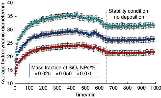
Fig. 1. Average hydrodynamic diameter of SiO2 nanofluids of different mass fractions in formation water. |
1.3. Core flooding experiment
To set the core samples at a common water-wet condition, they were cleaned with toluene and methanol, and then dried at 60 °C in an oven for 4 h. Then, the core samples were placed in a vacuum for 4 h. Subsequently, the samples were saturated with brine of 85 000, 40 000, 4000 mg/L. The liquid-permeability was then measured using a dynamic displacement setup with the core samples being mounted in a rubber sleeve subjected to a 13.78 MPa confining stress. The light non-polar crude oil (Table 1 ) was used for dynamic displacement experiments on an ultra-high-speed centrifuge. The experiments were performed using nanofluids with variable SiO2 NP mass fractions and brine and a total of nine clay-free, synthetic Berea sandstone core samples.
1.4. USBM index and contact angle measurements
Both contact angle measurements and USBM index measurements were performed to quantify the coupled impact of SiO2 NPs and LSW on the wettability alteration of sandstone rocks. The USBM index measurements required subjecting the core samples to forced drainage and imbibition cycles while mounted into an ultra-high-speed centrifuge. An ultra-rock high-speed centrifuge setup (model URC-628, Core Test Systems, Inc.) was used in this study to obtain the drainage and imbibition capillary pressure profiles. The rotational speed of the centrifuge was ramped from an estimated entry value (minimum 1000 r/min) to a maximum of 14 000 r/min. Details of the experimental setup and procedure for capillary pressure measurements and USBM calculations may be found in Alomair et al. [18]. It is worth noting that the drainage process took place with brines of different salinities but without adding NP. The forced imbibition of nanofluids was performed on brines with variable NP mass fractions. Details of the contact angle measurements with the drop shape analysis instrument from KRUSS have been described by Alomair et al. [18]
1.5. Oil-water IFT measurement
The IFT between the crude oil and nanofluids was measured at 25 °C using a pendant drop instrument (Fig. 2 ). The pendant-drop instrument has been widely accepted as an accurate and precise means for measuring the oil-water IFT, with an accuracy of ±0.05 mN/m [20]. Typically, this instrument consists of an experimental illuminating cell, a drop visualization system, and a data acquisition computer system [21]. The pendant drop shape and surface forces were evaluated optically from the drop shadow image. A numerical algorithm was used to approximate the actual drop shape using the Young-Laplace equation [21]. The output from the numerical approximation, consisting of the pendant drop radius of curvature at the apex position (Ro) and the shape parameter (B), was used to estimate the oil-water IFT as follows:
${{\sigma }_{\text{wo}}}=\frac{\Delta \rho \,gR_{o}^{2}}{B}$
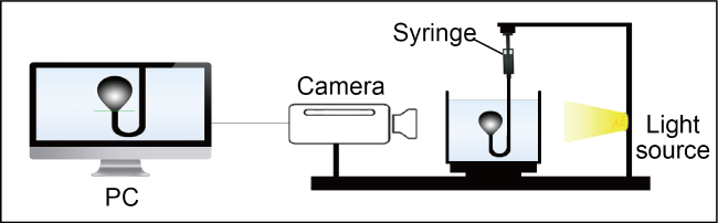
Fig. 2. A schematic of the instrument used to measure the oil-water IFT [20]. |
1.6. Zeta potential measurement
The spherical SiO2 NPs used in this study were electrically charged and may be considered colloidal. Therefore, the classical Derjaguin Landau Verwey and Overbeek (DLVO) theory adequately explains the NP colloidal behavior. The DLVO theory applies to homogeneous colloidal nanosuspensions that adhere to the following assumptions: (1) the nanosuspensions manifest dilute particle dispersion, (2) the particle aggregation is controlled mainly by competition between the attractive Van der Waal forces and the repulsive electrostatic forces ema-nating from the NP electrical double layer, and (3) the gravity and buoyancy forces are insignificant [2]. All these assumptions were categorically satisfied by the SiO2 nanofluids. The DLVO theory proclaims an electrical double layer (Stern layer and a diffuse layer) forming around the negatively charged NP substrates. The Zeta potential is measured at the Stern layer wall. It reflects the charge distribution at the solid-liquid interface in the Stern layer. The Zeta potential is used as a detailed index for nanosuspension stability. SiO2 nanofluids with absolute values of Zeta potential of approximately 30 mV or greater are considered stable. SiO2 nanofluids with absolute values of Zeta potential of 15-30 mV are moderately stable. In contrast, SiO2 nanofluids whose Zeta potential absolute value is less than 15 mV manifest low stability [2]. The Zeta potential of the nanosuspensions was measured using a Malvern Nano-ZS Zetasizer [2]. The sample cell and electrode were initially rinsed using methanol and de-ionized water. The nanosuspensions were sonicated for approximately 10 min. Approximately 1 min was allowed to pass for instrument balance before measuring the Zeta potential using the capillary cell.
2. Effects of NP mass fraction and brine salinity
2.1. USBM index
The effects of the NP mass fraction on the capillary-pressure curves during forced drainage and imbibition cycles, generated using three brine salinities with the synthetic Berea core sample, are shown in Fig. 3 . The upper part of the capillary pressure curve represents the forced drainage cycle whereas the lower part represents the forced imbibition cycle. Fig. 3 illustrates the raw data used to estimate the USBM index values under different NP mass fractions and brine salinities by evaluating the areas under the drainage and imbibition curves. This procedure is outlined in detail by Alomair et al. [18]
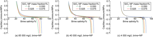
Fig. 3. Effect of NP mass fraction on the capillary pressure curves using three brine salinities and the synthetic Berea core sample. |
The capillary pressure measurements indicated that NP mass fraction and brine salinity influenced the area under the capillary pressure curves and USBM index values (Table 2 ). Fig. 4 shows that for any fixed brine salinity, an increase in NP mass fraction from 0 to 0.075% increased the USBM index by approximately 94%-100%. For instance, for a brine salinity of 85 000 mg/L, the USBM index increased from 0.263 5 to 0.525 9 when the NP mass fraction varied from 0 to 0.075%, indicating that the rock changed from the slightly water-wet to strongly water-wet. Similar changes were recorded for brine salinities of 40 000 mg/L and 4000 mg/L when the NP mass fraction varied from 0 to 0.075%.
Table 2. Effects of NP mass fraction and brine salinity on end-point parameters of capillary pressure curves of synthetic Berea sandstone |
| Brine type | SiO2 NP mass fraction/% | Area under drainage pressure curve/MPa | Area under imbibition pressure curve/MPa | USBM index |
|---|---|---|---|---|
| Formation water | 0 | 3.004 7 | 1.638 1 | 0.263 5 |
| 0.025 | 3.142 5 | 1.509 1 | 0.318 6 | |
| 0.050 | 3.136 3 | 1.221 1 | 0.409 7 | |
| 0.075 | 3.122 1 | 0.930 1 | 0.525 9 | |
| Seawater | 0 | 2.804 8 | 1.347 5 | 0.318 4 |
| 0.025 | 3.878 1 | 1.645 7 | 0.372 3 | |
| 0.050 | 3.830 4 | 1.320 4 | 0.462 6 | |
| 0.075 | 3.875 1 | 0.936 3 | 0.616 9 | |
| 10-times diluted sea water | 0 | 3.007 7 | 1.254 3 | 0.379 8 |
| 0.025 | 3.563 4 | 1.260 6 | 0.451 3 | |
| 0.050 | 3.580 1 | 1.108 6 | 0.509 1 | |
| 0.075 | 3.577 6 | 0.634 0 | 0.751 5 |
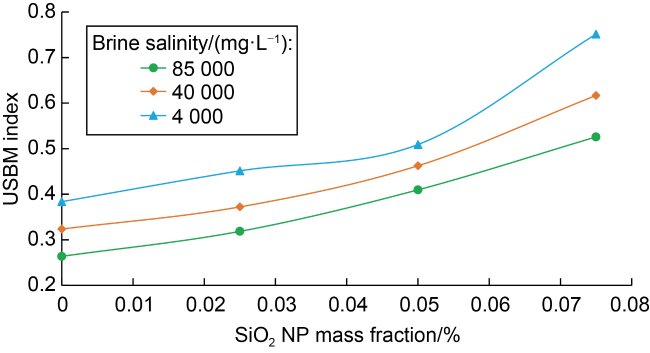
Fig. 4. Effect of NP mass fraction and brine salinity on the USBM index of clay-free synthetic Berea sandstones. |
Li et al. [3] reported that large structural disjoining pressure might have evolved, which can peel the oil droplets away from the solid surface, as NPs were driven by Brownian motion and electrostatic repulsion into a confined wedge between the oil droplets and the rock surface. The reported results of this study agreed with the simulations results of Chengara et al. [9] who confirmed that an increase in NP mass fraction increased the structural disjoining pressure, making it more water wet. The coupled effect of changing the brine salinity from 85 000 mg/L to 4000 mg/L and changing the NP mass fraction from 0 to 0.075% incurred approximately 185% change in USBM index from 0.263 5 to 0.751 5, indicating the rock changed from slightly water-wet to strongly water-wet state. These results indicated that the coupled effect of NPs and low water salinity had a significant impact on altering the wettability of synthetic clay-free Berea sandstones [22].
2.2. Contact angle
To validate the effect of the NP mass fraction on rock wettability alteration indicated by the USBM index measurements, static tests of contact angles were conducted under various brine salinities [18]. Typically, measured contact angles vary from 0 to 180°. Tiab and Donaldson [23] related the contact angle value to the rock wettability condition. A strong water-wet condition is indicated by a contact angle value in the vicinity of zero. A moderate water-wet condition is indicated by acute angles. On the other hand, a neutral wettability condition is indicated by contact angles in the vicinity of 90°. A strong oil-wet condition is reflected by a contact angle in the vicinity of 180°. Obtuse angles in the vicinity of 110° reflect moderate oil-wet conditions. The contact angle behavior as a function of NP mass fraction for various brine salinities is shown in Fig. 5 and Table 3 . The contact angles reported in Table 3 are average values. The relative error, in contact angle measurements, varied between 2% and 12%.
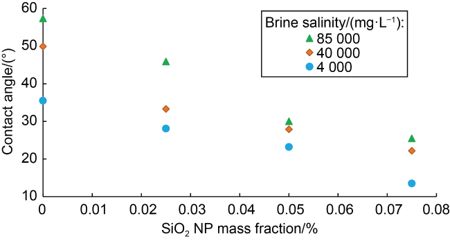
Fig. 5. Effect of NP mass fraction and brine salinity on the contact angle between Berea sandstone and oil. |
Table 3. Contact angle and IFT measurements for different brine salinities and NP mass fractions |
| Salinity/(mg•L−1) | SiO2 NP mass fraction/% | Average contact angle/(°) | IFT/(mN·m−1) | Relative error in IFT/% |
|---|---|---|---|---|
| 85 000 | 0 | 57.35±1.15 | 12.05 | 0.41 |
| 0.025 | 45.90±1.60 | 11.86 | 0.42 | |
| 0.050 | 30.01±2.75 | 11.79 | 0.42 | |
| 0.075 | 25.50±0.97 | 11.69 | 0.43 | |
| 40 000 | 0 | 49.90±1.27 | 11.89 | 0.42 |
| 0.025 | 33.30±0.47 | 11.41 | 0.44 | |
| 0.050 | 27.90±0.65 | 10.76 | 0.46 | |
| 0.075 | 22.20±0.30 | 10.69 | 0.47 | |
| 4000 | 0 | 35.50±0.41 | 10.73 | 0.47 |
| 0.025 | 28.10±0.30 | 10.51 | 0.48 | |
| 0.050 | 23.20±0.58 | 10.33 | 0.48 | |
| 0.075 | 13.50±1.65 | 10.28 | 0.49 |
As the NP mass fraction varied from 0 to 0.075%, for a brine salinity of 85 000 mg/L, the contact angle changed by approximately 56% from 57.35° (slightly water-wet state) to 25.5° (strongly water-wet state). A 56% change was recorded for a brine salinity of 40 000 mg/L, with the contact angle varying from 49.9° to 22.2° when the NP mass fraction varied from 0 to 0.075%. A contact angle change of approximately 62% was noticed for the 4000 mg/L brine when the NP mass fraction varied from 0 to 0.075%. Changing the brine salinity from 85 000 mg/L to 4000 mg/L and the NP mass fraction from 0 to 0.075% resulted in a 76% change in the contact angle from 57.35° (slightly water-wet state) to 13.5° (strongly water-wet state). These results indicated that the coupled effects of NPs and LSW on wettability alteration were significant for synthetic clay-free Berea sandstone, and were congruent with the measured USBM index results.
2.3. Oil-water IFT
A change in rock wettability to a more water-wet condition may be caused by reducing either the contact angle or the oil-water IFT. Young’s equation [23] describes the direct relationship between the cosine of the contact angle and the various IFTs, as follows:
$\cos \theta =\frac{{{\sigma }_{so}}-{{\sigma }_{sw}}}{{{\sigma }_{wo}}}$
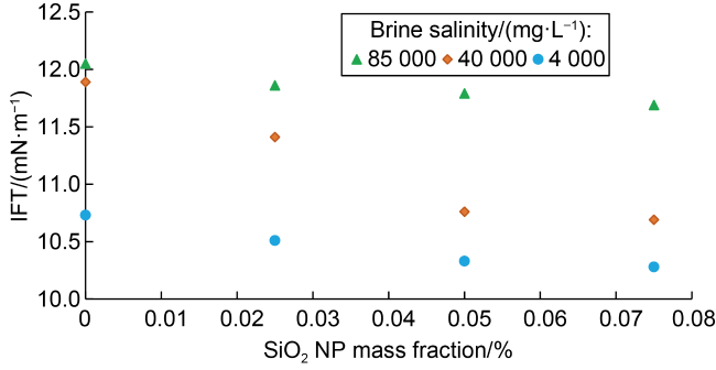
Eq. (2) indicates that an increase in the oil-water IFT should lead to an increase in the contact angle, provided that the difference (σso-σsw) remains the same. IFT measurements indicated that as the NP mass fraction increased, the oil-water IFT decreased systematically for all three brine salinities (Fig. 6 ). The relative error in IFT, based on the instrument error of ±0.05 mN/m, was estimated to be in the vicinity of 0.5% (Table 3 ). These results were also consistent with the observed contact angle and the USBM index results, confirming wettability alteration to a more water-wet condition with increasing NP mass fraction and decreasing brine salinity. Previous studies have confirmed that IFT increased by 9% as brine salinity varied from 4000 mg/L to 40 000 mg/L [24⇓-26], while IFT increased by 11% when the NP mass fraction is 0 in this study, with similar increase amplitude (Table 3 ).
Fig. 6. Effects of NP mass fraction and brine salinity on oil-water IFT. |
2.4. Nanofluid rheology
Shear stress and shear rate of the nanofluid suspensions were measured using a Brookfield digital rotational cone-and-plate rheometer model DV-III+ [29⇓-31]. The nanofluid was placed between the plate and the cone. The rotation of the cone, at an arbitrary rate, induced a measured torque applied by the nanofluid on the cone. This torque, or viscous drag, was converted to shear stress. The rotational speed was converted to a shear rate[31]. The nanofluids did not appear to significantly alter the rheological behavior of the base fluids. For the three NP mass fractions, the nanofluids exhibited a Newtonian fluid characteristic of shear stress being linearly dependent on shear rate. As the NP mass fraction increased from 0.025% to 0.075%, the viscosity of the nanofluids displayed an insignificant variation from 1.0 mPa·s to 1.1 mPa•s. The observed insignificant change in the suspension viscosity confirmed that nanofluids were brine-base dilute dispersions [32].
2.5. Nanofluid stability
Nanofluid stability is essential for the successful application of NPs in EOR projects. Nanosuspensions may occasionally show instability due to severe NP aggregations, causing large clusters of NPs that destabilize the nanosuspension by sedimentation. This aggregation is caused by either domination of the attractive Van der Waal forces over the repulsive electrostatic forces [33] or collision among the NPs. The instability issues are likely to degrade the beneficial attributes of the NPs and impair rock permeability. In this study, the stability of the nanofluids was assessed by measuring the Zeta potential of the nanosuspensions [33]. All measurements were performed at ambient temperature of 25 °C.
As seen in Table 4 , the measured Zeta potential values for the nanofluids prepared with the 4000 mg/L salinity brine were approximately −30 mV for the three NP mass fractions. These Zeta potential values classified the nanofluids based on 4000 mg/L brine as stable [34]. The nanofluids based on the 40 000 mg/L brine appeared to have moderate stability, since the Zeta potential values measured for these suspensions were in the vicinity of −15 mV. In contrast, the nanofluids based on 85 000 mg/L brine exhibited Zeta potential values ranging from −7 mV to −3 mV, which may be considered slightly stable [2]. The lack of stability demonstrated by the 85 000 mg/L brine nanosuspensions may be explained by the collapse of the Debye-Huckel length of the electrical double layer due to the relatively high base fluid salinity [33]. Van der Waal forces overcame the repulsive electrostatic forces, causing the NPs to agglomerate and destabilize the nanosuspension. The stability data analysis suggested an optimal base fluid salinity of 4000 mg/L for LSW flooding added with SiO2 NPs.
Table 4. Zeta potential measurements for nanosuspensions |
| Salinity/(mg•L−1) | SiO2 NP mass fraction/% | Zeta potential/mV |
|---|---|---|
| 0.025 | −6.50 | |
| 85 000 | 0.050 | −2.56 |
| 0.075 | −4.45 | |
| 0.025 | −15.70 | |
| 40 000 | 0.050 | −12.80 |
| 0.075 | −12.40 | |
| 0.025 | −30.30 | |
| 4000 | 0.050 | −27.50 |
| 0.075 | −28.90 |
2.6. NP retention
Permeability impairment due to plugging caused by suspended solids is a primary concern in the industrial application of nanofluids in EOR. Injectivity or production may be reduced because of the permeability reduction [35]. Costly workovers and frequent stimulation jobs may be required to remedy these problems. The gradual decrease in permeability may be related to the plugging of the formation at the wellbore and in the near-wellbore region, by small and suspended solids contained in the injected nanofluid. The entrainment of large particles on the surface of the formation at the wellbore causes the buildup of an external filter cake. In contrast, the entrainment of smaller particulates, which invade deeper, forms an “internal” filter cake in the near-wellbore region. An internal filter cake is generally more damaging than an external filter cake [36]. This is attributed to the relative inaccessibility of the internal filter cake. In general, particles with diameters larger than 33% of the mean pore-throat diameter bridge and form an external filter cake. On the other hand, particles with diameters between 14% and 33% of the mean pore-throat diameter tend to invade deeper into the formation and form an internal filter cake. Particulates with diameters smaller than 14% of the mean pore-throat diameter usually cause no blockage [37].
The dynamic displacement experiments were performed on nine synthetic Berea core samples with a porosity of approximately 20% and absolute permeability of (53-68)×10−3 μm2. These core samples were flooded by nanosuspensions with varying NP mass fractions and base fluid salinity (Table 5 ). Rock permeabilities were evaluated after the nanosuspension flooding (Table 5 ). A visual inspection of the core samples revealed an external NP filter cake buildup at the end of the nanosuspension flooding. These filter cakes were gently scraped off manually, and then the core samples were subjected to final brine flooding with the same direction as the original nanosuspension flood. The permeabilities of all core samples at the end of the brine flooding were evaluated and reported in Table 5 . Table 6 shows that the relative change in permeability after the nanosuspension flooding varied between 9% and 44%. Most of this change was caused by an external NP filter cake rather than deep filtration or retention damage in the rock. Indeed, NP retention damage was inferred from evaluating rock permeability after brine flooding (Table 6 ). NP retention caused a reduction in permeability, varying between 4% and 10%.
Table 5. Effect of NP mass fraction on rock permeability |
| NP mass fraction/ % | Brine salinity/ (mg•L−1) | Initial permeability/ 10−3 μm2 | Permeability After nanofluid flooding/ 10−3 μm2 | Permeability After brine flooding/ 10−3 μm2 |
|---|---|---|---|---|
| 0.025 | 85 000 | 53.397 | 48.643 | 51.205 |
| 40 000 | 64.866 | 47.218 | 59.810 | |
| 4000 | 67.406 | 51.035 | 65.000 | |
| 0.050 | 85 000 | 52.535 | 41.404 | 50.552 |
| 40 000 | 65.300 | 43.772 | 62.453 | |
| 4000 | 68.268 | 45.431 | 64.916 | |
| 0.075 | 85 000 | 52.987 | 28.079 | 47.822 |
| 40 000 | 65.108 | 35.369 | 58.724 | |
| 4000 | 67.449 | 37.870 | 61.430 |
Table 6. Relative change of absolute permeability of synthetic Berea core samples |
| Experiment | Porosity/ % | Average pore radius/mm | Initial permeability/ 10−3 μm2 | Relative change after nanofluid flooding/% | Relative change after brine flooding/% |
|---|---|---|---|---|---|
| 85 000 mg/L Brine+0.025% SiO2 | 19.8 | 0.52 | 48.6 | 8.9 | 4.1 |
| 85 000 mg/L Brine+0.050% SiO2 | 19.3 | 0.58 | 41.4 | 21.2 | 3.8 |
| 85 000mg/L Brine+0.075% SiO2 | 19.5 | 0.59 | 28.1 | 47.0 | 9.8 |
| 40 000 mg/L Brine+0.025% SiO2 | 19.6 | 0.52 | 47.2 | 27.2 | 7.8 |
| 40 000 mg/L Brine+0.050% SiO2 | 19.1 | 0.58 | 43.8 | 33.0 | 4.4 |
| 40 000 mg/L Brine+0.075% SiO2 | 19.3 | 0.59 | 35.4 | 45.7 | 9.8 |
| 4000 mg/L Brine+0.025% SiO2 | 19.6 | 0.52 | 51.0 | 24.3 | 3.6 |
| 4000 mg/L Brine+0.050% SiO2 | 19.2 | 0.58 | 45.4 | 33.5 | 4.9 |
| 4000 mg/L Brine+0.075% SiO2 | 19.3 | 0.59 | 37.9 | 43.9 | 8.9 |
An approximate value of the average pore radius of the rock samples was estimated using Eq. (3) [38]. An average pore radius ranging from 0.52 mm to 0.59 mm was obtained for the set of core samples used in the dynamic displacement experiments (Table 6 ). The spherical NPs used in this study have a radius varying from 15 nm to 20 nm. In the absence of NP agglomeration, the NP radius was less than 4% of the average pore radius. Therefore, in theory, in the absence of NP agglomeration, no particle permeability reduction can be expected. Nevertheless, the permeability reduction of 4%-10% after brine flooding indicated a minor amount of NP retention. This slight NP retention was confirmed by the measured absolute value of Zeta potential that appeared to decrease with increasing NP mass fraction (Table 4 ). As indicated in Table 6 , the permeability reduction after nanofluid flooding was less severe for low NP mass fractions (0.025%-0.050%) than for the high NP mass fraction (0.075%). This minor permeability impairment may have been caused by the slight increase in NP agglomeration that occurred when high-salinity base fluids and relatively high NP mass fractions were used.
${{\bar{r}}_{p}}=\sqrt{{}^{K}/{}_{\phi }}$
2.7. Oil recovery
Table 7. Recovery factor and related parameters obtained from capillary pressure measurements |
| Salinity/ (mg·L−1) | SiO2 mass fraction/% | Irreducible water saturation/% | Remaining oil saturation/% | Recovery factor/% |
|---|---|---|---|---|
| 85 000 | 0 | 21 | 25 | 68.9 |
| 0.025 | 21 | 23 | 71.0 | |
| 0.050 | 21 | 21 | 73.9 | |
| 0.075 | 21 | 18 | 77.8 | |
| 40 000 | 0 | 24 | 22 | 70.5 |
| 0.025 | 24 | 21 | 72.4 | |
| 0.050 | 24 | 19 | 74.4 | |
| 0.075 | 24 | 15 | 79.7 | |
| 4 000 | 0 | 26 | 20 | 72.8 |
| 0.025 | 26 | 18 | 75.5 | |
| 0.050 | 25 | 16 | 78.2 | |
| 0.075 | 26 | 13 | 82.3 |
$R=\frac{1-{{S}_{w\text{i}}}-{{S}_{or}}}{1-{{S}_{wi}}}$
For the three investigated brine salinities, as the NP mass fraction varied from 0 to 0.075%, the oil recovery factor increased by approximately 9% (Table 7 ). These results agreed with those reported by Bila et al. [12] and Omran et al. [14]. As shown in Table 7 , the coupled effect of LSW (salinity of 4000 mg/L) and SiO2 NPs (mass fraction of 0.075%) appeared to have increased the oil recovery factor by approximately 13 percentage points. As discussed earlier, an increase in NP mass fraction and a decrease in brine salinity altered the rock wettability to a strong water-wet condition, thus improved the oil recovery.
It is important to emphasize that the results of this study were obtained at ambient temperature. Most of the literature reports conflicting opinions regarding the effects of elevated temperatures on the stability of NPs and on the oil recovery enhancement caused by their application [33,39 -40]. Therefore, in summary, more research is needed to investigate: (1) the impact of temperature on the agglomeration tendencies of SiO2 NPs when applied during the LSW flooding of sandstones and (2) the impact of SiO2 NPs on the oil recovery enhancement of LSW flooding at reservoir temperature conditions.
3. Conclusions
This experimental study evaluated the coupled effects of hydrophilic SiO2 NPs and LSW on the wettability alteration of clay-free synthetic sandstones. Results of this experimental study proved that LSW immiscible displacement coupled with hydrophilic SiO2 NPs was effective in altering wettability toward a more water wet condition. With the decreasing brine salinity and increasing NP mass fraction, the oil-water IFT and contact angle decrease. The overall wettability alteration was evidenced by the significant increase in the USBM index. The highest incremental oil recovery factor recorded was approximately 13 percentage points under NP mass fraction of 0.075% and brine salinity of 4000 mg/L.
The hydrophilic SiO2 NPs seemed to cause slighter permeability impairment due to the NP retention at lower mass fraction (0.025%-0.050%) compared to higher NP mass fraction (0.075%). Under the condition of low brine salinity of 4000 mg/L with an NP mass fraction of 0.025%, the nanosuspensions appeared to be stable and caused minimal permeability impairment. In summary, this study revealed a widespread potential for the application of hydrophilic colloidal SiO2 NPs coupled with LSW displacement in oil-saturated sandstones.
Acknowledgments
The authors would like to acknowledge Kuwait University General Research Facilities (GE01/17, GE01/07, and GS03/01) for their support in conducting the necessary experimental work of this study.
Nomenclature
B—shape parameter, dimensionless;
g—acceleration due to gravity, 9.81 m/s2;
K—absolute permeability, m2;
R—oil recovery factor, %;
Ro—pendant drop radius of curvature at the apex position, m;
${{\bar{r}}_{p}}$—average pore radius, m;
Sor—residual oil saturation value measured at the end of the forced imbibition cycle, %;
Swi—water saturation value measured at the end of the forced drainage cycle, %;
Δρ—density difference between fluids, kg/m3;
θ—contact angle, (°);
σso—solid substrate-oil IFT, N/m;
σsw—solid substrate-water IFT, N/m;
σwo—oil-water IFT, N/m;
ϕ—porosity, %.