

Introduction
China has rich tight oil resources with a great development potential and recoverable resources of 44.8×10⁸ t, which is an important strategic alternative energy. Compared with conventional reservoirs, tight oil reservoirs have low porosity, low permeability, small pore throats and poor connectivity, so that they cannot be efficiently developed by conventional fracturing technology [1⇓-3]. In recent years, the development mode of "horizontal well + volume fracturing + shut-in well" has been applied in China and abroad to develop tight oil. In other words, the well is shut in immediately after volume fracturing, and then opened for production after a certain period of time. This operation can increase oil production while effectively reducing water production. However, field practice has demonstrated that if the shut-in time is too short, the oil breakthrough will delay after the well is put into production, and the initial water cut is high. If the shut-in time is too long, the energy dissipation is severe, resulting in short flowing period and low cumulative oil production. Therefore, the shut-in system centered on the shut-in time after fracturing is a key issue that urgently needs to be solved in the efficient development of tight oil [4⇓⇓-7].
Dutta et al. conducted a study on the mechanism of imbibition displacement of shut-in wells through core experiments, and believed that the period from imbibition displacement to diffusion imbibition was the best shut-in time, and established a theoretical calculation formula for the shut-in time [8⇓-10]. Shang et al. established a conventional single hydraulic fracture model and a single-stage-fracture network model, analyzed the pressure variation rule during the shut-in period in tight oil reservoirs, and basically clarified the energy storage mechanism of the shut-in wells after fracturing [11-12]. Wang et al. established a single-phase numerical model of hydraulic fracture flow and a two-dimensional planar numerical model of multiphase flow, and compared and analyzed the influence of different shut-in time on well productivity [13⇓⇓-16]. Wang et al. used the inversion theory based on pressure drop data to divide flow stages during shut-in based on pressure drop characteristic curves, calculated the pressure and pressure derivative curves at different permeability, and established permeability and boundary effect time charts [17-18]. Yaich et al. calculated the production of fractured wells after different shut-in time on site, and built an empirical formula for cumulative oil production and shut-in time[19-20]. Most domestic and foreign scholars focused on experimental and theoretical research on rational shut-in time at micro scale, but less on field-sized research. The physical properties of reservoirs in different blocks are different, so the applicability of empirical formulas is limited. The use of these methods for the design and field construction of shut-in systems after fracturing has certain limitations.
This paper establishes a three-dimensional, oil-water two-phase flow numerical model involving volume fracturing, shut-in and production of tight oil horizontal wells, based on imbibition replacement and oil saturation rebalancing in matrix and fractures during the shut-in process after fracturing, develops an optimization method for shut-in time with the goal for shortening oil breakthrough time and achieving rapid oil breakthrough, and discusses the influences of key parameters of reservoir and fracturing on shut-in time.
1. Integrated numerical model for volume fracturing, shut-in and production
1.1. Physical model
The integrated development methods include three continuous physical processes: volume fracturing, imbibition displacement and production. During volume fracturing process, fracturing fluid is injected into the hydraulic fractures through the horizontal wellbore under high pressure, and then filtered into the reservoir. After the completion of volume fracturing, the well is shut in, all hydraulic fractures are filled with fracturing fluid, and the pressure in the fractures increases. The fracturing fluid in the hydraulic fractures will keep flowing into the matrix under pressure difference, while oil in the matrix will enter the hydraulic fractures under capillary pressure. The saturation balance in the reservoir is broken, and the oil saturation in the fractures gradually increases, while the oil saturation in the matrix gradually decreases until they reach equilibrium again. After the end of shut-in, the well is opened for production. Oil and water in the reservoir are produced through the horizontal wellbore, and their production at the wellhead at different production time can be calculated. Therefore, through simulation calculation, oil saturation in matrix and fractures at different shut-in time, and the oil and water production performance at wellhead are obtained, so as to optimize the rational shut-in time.
Based on the characteristics of fracturing, shut-in and post-fracturing oil and water production performance, an integrated physical model is established (Fig. 1 ). The basic assumptions of the model are as follows: (1) Fracturing fluid is a single water phase, there are only two phases (oil and water) that are not mutually soluble in reservoir, and imbibition and flow mainly occur between hydraulic fractures and matrix; (2) Reservoir temperature changes little in the process of fracturing operation, shut-in and production, so the flow in the model is isothermal unsteady flow, without considering the influence of temperature change; (3) Strong heterogeneity and gravity of tight reservoir are considered; (4) Pores in tight oil reservoirs are small and the throats are complex, so the effect of capillary pressure is considered; (5) Horizontal wellbore is along the x-axis direction, while hydraulic fractures are vertical, and parallel to the y-axis direction. Hydraulic fractures are perpendicular to the horizontal wellbore.
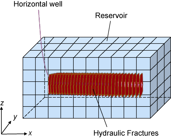
Fig. 1. Integrated physical model of volume fracturing, shut-in and production. |
1.2. Mathematical model
Tight oil reservoirs are characterized by small pores and throats, narrow flow channels and large flow resistance. Fluid flow in tight oil reservoirs is a slow nonlinear Darcy flow. After large-scale fracturing of horizontal wells, there are complex hydraulic fractures in the reservoir. The fluid flow in tight oil reservoirs is obviously different from that in conventional reservoirs. Therefore, in the integrated modeling process, a dual-medium model was used as the mathematical model, that is, there are two types of media, matrix and fracture in the reservoir, which have different pore structures and flow characteristics. Based on the law of conservation of mass and non-Darcy's law, and considering the influence of capillary pressure, the basic control equation for oil and water two-phase flow in the matrix can be obtained [21⇓-23]:
The first term on the left of Eq. (1) represents the oil phase non-Darcy flow in the matrix. Taking into account the influence of capillary pressure, oil phase pressure is characterized by water phase pressure and capillary pressure. The first term on the left of Eq. (2) means the water phase non-Darcy flow in the matrix. The second term on the left of Eq. (1) and that of Eq. (2) represent the oil phase and the water phase exchange between the matrix and the fractures.
Fractures have high conductivity, so fluid flow in the fractures follows the classical Darcy equation without considering the influence of capillary pressure. Based on the law of conservation of mass and Darcy's law, the basic control equation for oil and water two-phase flow in fractures is obtained [21⇓-23]:
The first term on the left of Eq. (3) represents the oil phase Darcy flow in the fractures, and oil phase pressure is equal to water phase pressure without considering the influence of capillary pressure. The first term on the left of Eq. (4) is the water phase Darcy flow in the fractures. The second term on the left of Eq. (3) and that of Eq. (4) represent the source and sink of oil phase and water phase in the fractures, and the third item represents the oil phase and water phase exchange between the matrix and the fractures.
To solve the integrated numerical model, a series of auxiliary equations are needed. In the model, two-phase flow of oil and water occurs in the matrix and the fractures, and the saturation equation can be expressed as:
In the model, the capillary pressure is considered for matrix, while it is not considered for fractures. Therefore, the capillary pressure equation is:
Tight oil reservoirs are sensitive to stress. The stress sensitive equations of permeability and porosity are expressed as [24]:
During the simulation process, the reservoir parameters at the end of fracturing are used as the initial parameters for the shut-in stage, and the reservoir parameters at the end of shut-in are used as the initial parameters for the production stage. Therefore, only the initial parameters of the reservoir during fracturing are set in the numerical model. The reservoir in a new well has not been developed, so both the matrix and the fractures are in the original state, with the same initial pressure and saturation. During the shut-in and production stages, the initial pressure and oil saturation in the matrix and the fractures are obtained through simulation calculations. Volume fracturing is the process of injecting fracturing fluid at a high rate and in a short time, so the internal boundary condition of the model in the fracturing process can be set to a constant flow rate with the injected liquid as water, and the well should be shut in immediately after fracturing. The internal boundary condition of the model in the shut-in process is set as closed boundary. After the end of shut-in, the well is opened for production. When the horizontal well produces at constant bottom-hole pressure, the internal boundary condition of the model is set to be a constant pressure condition. When the horizontal well produces at a constant water production, the internal boundary condition of the model is set to be a constant production condition. Considering no energy to supplement, such as water supply, the outer boundary of the reservoir is set to be a closed boundary from fracturing, shut-in to production in the model.
1.3. Model solution
To solve the numerical model, the finite difference method is adopted to disperse the control equations of two-phase flows in matrix and fractures. Combined with auxiliary equations, initial conditions and boundary conditions, the difference equations are solved simultaneously by implicit pressure and implicit saturation [25]. The coefficient and derivative of each variable at each time step are iterated, that is, at the beginning of step n+1, the coefficients in the equations are calculated by the variables solved at the end of the nth step, and the equations are iterated until the accuracy is met. Finally, the pressure and saturation can be obtained at different time.
1.4. Model validation
A numerical model was established based on the parameters of reservoir physical property and fracturing of Well A in the Songliao Basin, NE China. Whether the model is consistent with the actual geological body and fracturing construction results is judged by comparing the simulated production curve with the actual production data of Well A. The reservoir porosity of Well A is 13.5%, and the permeability is 0.3×10⁻³ μm2. The relative permeability curves of oil and water and capillary pressure in the matrix were obtained from core experiments (Figs. 2 and 3 ). Since the hydraulic fractures have high conductivity, the capillary pressure was not taken into account. The relative permeability curves of oil and water are two straight lines with slopes of −1 and 1, respectively, and intersect at the water saturation of 50% [26]. For the Well A, 89 clusters and 26 stages were fractured, using total fluid volume of 40 895 m3 and total sand volume of 1620 m3, at flow rate of 6-10 m3/min. The hydraulic fracture parameters of each stage were inverted from the fracturing curve. The fracture half-length is 112-127 m, and the fracture conductivity is (35-59)×10−3 μm2·m. The well was put into production after shutting in for 20 d.
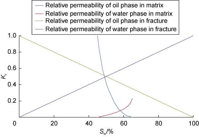
Fig. 2. Oil-water relative permeability curves of matrix and fracture. |
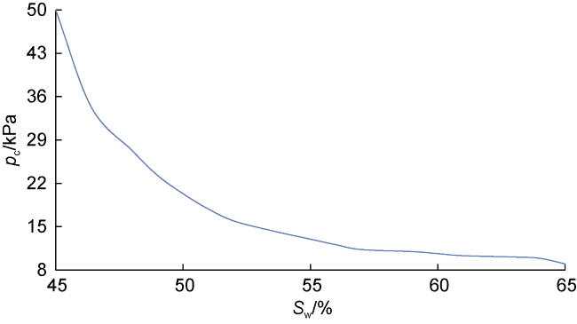
Fig. 3. Capillary pressure curve. |
The comparison of simulated results with actual production data of Well A (Fig. 4 ) shows that the simulated daily and cumulative oil production curves are basically consistent with the actual ones, indicating that the integrated numerical model of volume fracturing, shut-in and production is effective, and can be used to optimize the post-fracturing shut-in time.
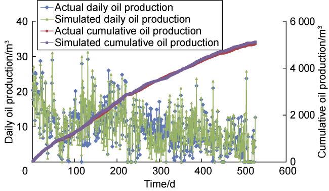
Fig. 4. Comparison of simulation results with actual production data of Well A. |
2. Optimization of shut-in time
2.1. Principle of saturation rebalancing during the shut-in process after tight oil fracturing
The permeability of the tight oil reservoir in Block Y is (0.08-0.37)×10−3 μm2, with an average of 0.21×10⁻³ μm2, and the porosity is 8.1%-14.2%, with an average of 12.3%. Core B-1-1 taken in the target layer in Well B in Block Y was used for slick water spontaneous imbibition experiment. The length of the core is 50 mm, the diameter is 25 mm, the porosity is 12.5%, and the permeability is 0.24×10⁻³ μm2. Since the porosity and the permeability are very close to the average value in Block Y, the core is very representative. The early stage of the spontaneous imbibition curve (Fig. 5 ) is the capillary imbibition stage, when the capillary force is the main driving force, and slick water is sucked into the main connected pore network. Due to the existence of micro and nano pores in the tight oil reservoir, the late stage of the curve is the diffusion imbibition stage, manifested by the diffusion of slick water into the nano pores after entering the large matrix pores.
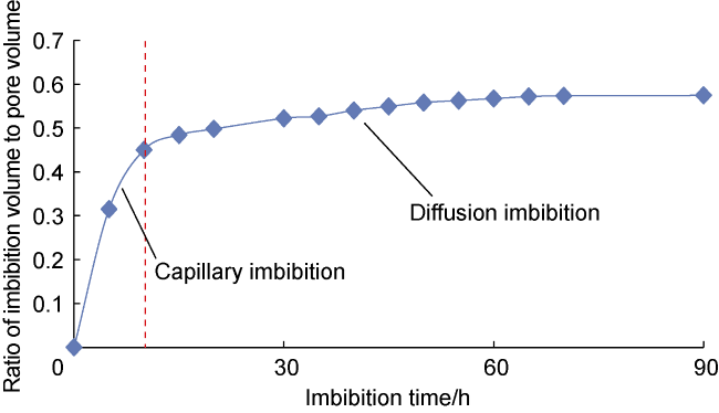
Fig. 5. Slick water imbibition curve of Core B-1-1. |
In the same way, Core B-1-2 taken in the target layer in Well B was used for slick water imbibition displacement experiment. The length of the core is 50 mm, the diameter is 25 mm, the porosity is 12.2%, and the permeability is 0.19×10⁻³ μm2. Core B-1-2 and Core B-1-1 were taken in the same well and the same target layer, and they are both representative. The relationship between imbibition displacement volume and equilibrium time (Fig. 6 ) shows that the displacement volume of slick water increases steadily, and tends to be stable after about 75 h, when the oil saturation reaches equilibrium, and the displacement volume reaches its maximum. Fig. 7 shows the microscopic imbibition process monitored by nuclear magnetic resonance.
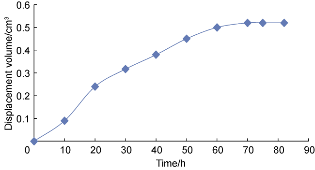
Fig. 6. Relationship between slick water imbibition displacement volume and time of Core B-1-2. |
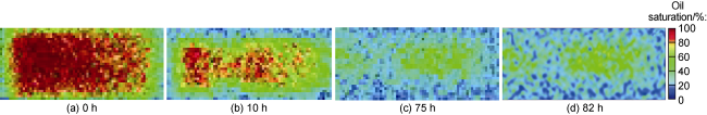
Fig. 7. NMR images of microscopic imbibition process in Core B-1-2. |
2.2. Optimization of rational shut-in time
Large-scale volume fracturing and shut-in of tight oil wells increase the contact area and contact time between the fracturing fluid and the fractures and the matrix, gives a full play to the imbibition displacement by capillary force, breaks the oil-water saturation balance in the reservoir. When fracturing fluid enters the reservoir and stays in small pores, it displaces crude oil from the small pores to fractures, and redistributes the oil and water saturation in the reservoir. When the saturation reaches equilibrium again, the maximum replacement quantity is reached, corresponding to the longest rational shut-in time. At different shut-in time, the ratio of oil to water measured at wellhead is different. If the shut-in time is too short, oil saturation in fractures is low, and almost all fluid produced is water. When shut in after a critical time, the liquid produced starts to contain oil, corresponding to the shortest rational shut-in time. Under this condition, the oil breakthrough time of the well is short and the water cut is relatively low.
On the basis of the integrated numerical model, the optimization of shut-in time was carried out by calculating the time when the oil saturation in matrix and fractures reached equilibrium during shut-in, and the oil content of wellhead produced fluid after different shut-in time during the process of saturation reaching equilibrium again (Fig. 8 ). The specific steps are as follows: (1) Based on reservoir, fracture, fluid, and wellbore parameters, combined with the design of pumping of horizontal well fracturing, establishing an integrated numerical model; (2) Simulate the process of volume fracturing, shut-in, and production of horizontal wells, calculate the saturation in matrix and fractures after different shut-in time, as well as the oil content of wellhead produced fluid; (3) Based on the time required to achieve saturation equilibrium between the matrix and fractures, and the shut-in time for the earliest oil breakthrough, determine the rational shut-in time.
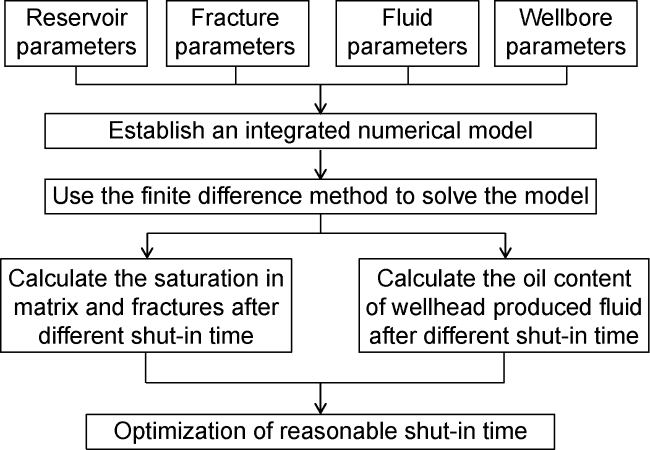
Fig. 8. Optimization method for shut-in time after horizontal well volume fracturing. |
A numerical model was established based on the reservoir properties and fracturing parameters of Well B to optimize the reasonable shut-in time. The porosity of the reservoir in Well B is 13.1%, and the permeability is 0.26×10⁻³ μm2. The relative permeability curve and the capillary pressure curve are shown in Fig. 2 and Fig. 3 . The fracture parameters were obtained from the simulation through the fracturing optimization software based on the pumping program. The average fracture half-length is 180 m and the average fracture conductivity is 50×10−3 μm2·m. The oil saturation distribution in the matrix and fractures after different shut-in time was obtained by simulation calculation (Figs. 9 and 10 ). After volume fracturing, all fractures were filled with water, and the matrix performed spontaneous imbibition under capillary pressure after shut in. Due to the difference in pore size of the matrix, small pores have a greater imbibition rate under higher capillary pressure. The fracturing fluid imbibed displaces crude oil from small pores to large pores, and finally into fractures with higher conductivity. This is the displacement between oil and water, which redistributes oil and water saturation in the reservoir. After 25 d of shut-in, the oil saturation in the matrix and fractures tended to be basically consistent, it can be considered that the equilibrium has been reached again. Therefore, the longest shut-in time after volume fracturing in Well B is 25 d, and the displacement quantity reaches the maximum.
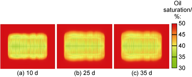
Fig. 9. Oil saturation distribution at different shut-in time. |
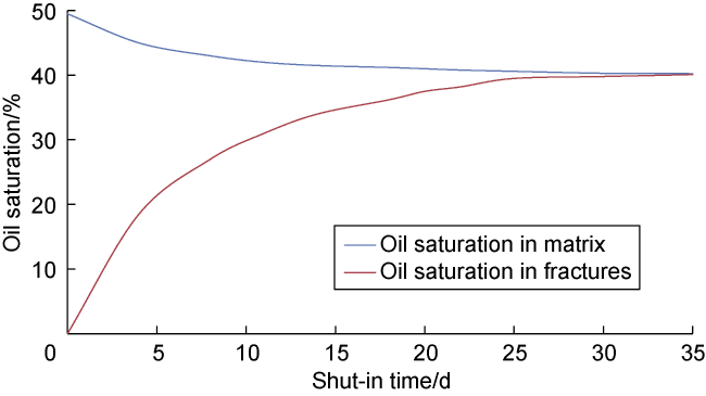
Fig. 10. Variation curve of oil saturation of fracture and matrix with shut-in time. |
The change of oil content at the wellhead with shut-in time was obtained through simulation calculation (Fig. 11 ). The oil saturation in the matrix and fractures varied with shut-in time, resulting in different oil content of wellhead produced fluid. It can be seen that when the shut-in time is less than 14 d, the oil content is very low, and increases slowly as the shut-in time increases. After 14 d, the oil content significantly increases, and begin to rapidly increase with time. Therefore, the shortest shut-in time after volume fracturing of Well B is 14 d, and oil can be produced immediately after opening again.
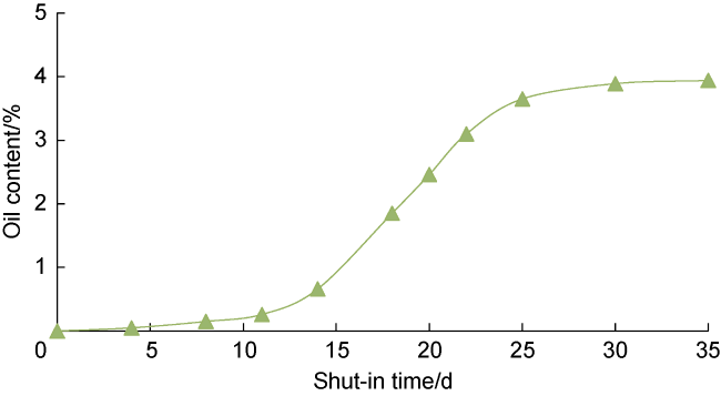
Fig. 11. Variation curve of oil content of wellhead produced fluid with shut-in time. |
3. Factors influencing shut-in time
Wells C, D and E were selected to establish an integrated numerical model of volume fracturing, shut-in and production. The shortest and the longest shut-in time was simulated at different permeability, porosity, fracture half-lengths and fracturing fluid volumes, and the factors influencing the shut-in time were analyzed. The basic parameters of the three wells are shown in Table 1 .
Table 1. Basic parameters of wells C, D and E |
| Well | Porosity/ % | Permeability/ 10−3 μm2 | Formation pressure/MPa | Reservoir depth/m | Initial oil saturation/% | Stimulated length/m | Number of fracture clusters |
|---|---|---|---|---|---|---|---|
| C | 13.1 | 0.26 | 21.3 | 2183 | 41 | 1178 | 148 |
| D | 12.0 | 0.10 | 22.4 | 2230 | 45 | 1265 | 158 |
| E | 8.3 | 0.05 | 23.2 | 2342 | 43 | 1340 | 167 |
3.1. The influence of permeability
The relationship between the permeability and the shortest and the longest shut-in time (Fig. 12 ) shows that the permeability is negatively related with the shortest and the longest shut-in time. The higher the permeability, the faster the pressure diffusion, the faster the oil and water flow in the matrix and fractures, the shorter the time required for oil saturation to reach equilibrium during shut-in, the shorter the time required for oil production from the wellhead, and the shorter the longest and the shortest shut-in time.
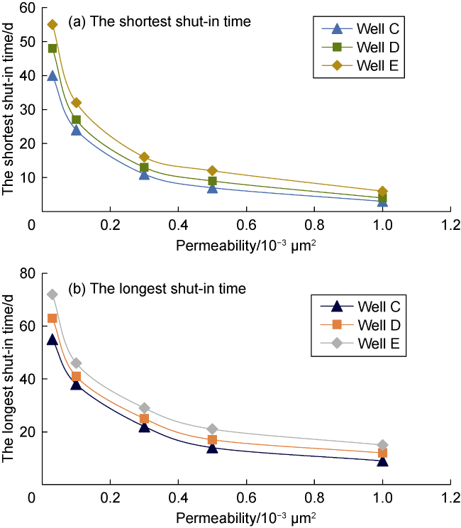
Fig. 12. Relationship between permeability and shut-in time. |
3.2. The influence of porosity
The relationship between the porosity and the shortest and the longest shut-in time (Fig. 13 ) shows that the porosity is negatively related with the shortest and the longest shut-in time. The smaller the porosity, the slower the pressure transmission, the longer the time required for oil saturation to reach equilibrium during shut-in, the longer the time required for oil production from the wellhead, and the longer the longest and the shortest shut-in time.
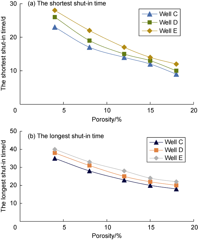
Fig. 13. Relationship between porosity and shut-in time. |
3.3. The influence of fracture half-length
The relationship between the fracture half-length and the shortest and the longest shut-in time (Fig. 14 ) is similar to the porosity and the permeability. It is also a negative relationship with the shortest and the longest shut-in time. The shorter the fracture half-length, the smaller the contact area between the matrix and the fracture, the longer the time required for oil saturation to reach equilibrium during shut-in, the longer the time required for oil production from the wellhead, and the longer the longest and the shortest shut-in time.
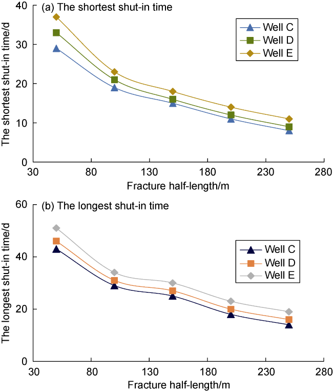
Fig. 14. Relationship between fracture half-length and shut-in time. |
3.4. The influence of fracturing fluid volume
The relationship between the fracturing fluid volume and the shortest and the longest shut-in time (Fig. 15 ) is contrary to the influence of the above three parameters. It is positively related with the shortest and the longest shut-in time. At constant matrix/fracture conductivity, the larger the fracturing fluid volume, the longer the fluid flowing time, the longer the time required for oil saturation to reach equilibrium during shut-in, the longer the time required for oil production from the wellhead, and the longer the longest and the shortest shut-in time.
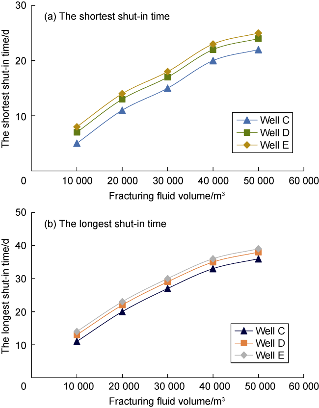
Fig. 15. Relationship between fracturing fluid volume and shut-in time. |
4. Field application
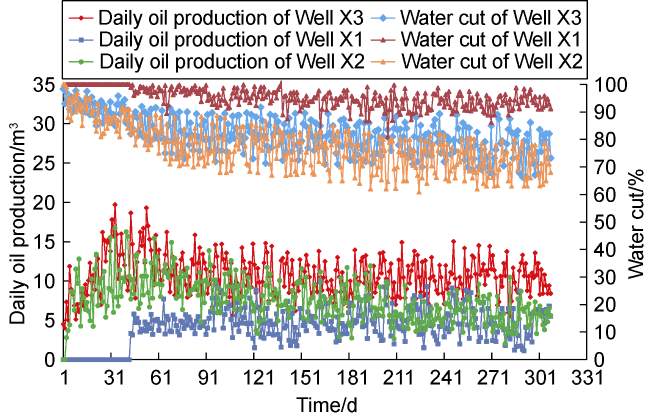
Block X is a typical tight oil block in the Songliao Basin. The porosity of the reservoir is 7.00%-12.00%, with an average of 9.75%, and the permeability is (0.06-0.35)× 10−3 μm2, with an average of 0.22×10⁻³ μm2. The reservoir has poor physical properties and uneven distribution of pore throat size. It is a water-wet reservoir with less developed natural fractures. The shut-in time after fracturing in the early stage of Block X was only determined by field experience. Some horizontal wells after fracturing were only shut in for 1-15 d, have a long oil breakthrough period and high water content. Some horizontal wells were shut in for 50-70 d, have low formation energy and production. For example, the horizontal section of Well X1 is 1627 m, the interval between stages is 60 m, the fracturing fluid volume is 37 289 m3, the sand volume is 2964 m3, the flow rate is 6-12 m3/min, the shut-in time is 12 d, the oil breakthrough time is 43 d, the current daily oil production is 5.5 m3, and the water cut is 91.2%. Well X2 has the horizontal section of 1840 m, the interval between stages is 61.3 m, the fracturing fluid volume is 38 758 m3, the sand volume is 3061 m3, the flow rate is 6-12 m3/min, the shut-in time is 55 d, the oil breakthrough time is 2 d, the current daily oil production is 5.6 m3, and the water cut is 68.0% (Fig. 16 ).
Fig. 16. Production performances of wells X3, X1, X2. |
Well X3 has the horizontal section of 1772 m, the interval between stages is 60.6 m, the fracturing fluid volume is 38 544 m3, the sand volume is 3040 m3, the flow rate is 6-12 m3/min, and its basic parameters are similar to wells X1 and X2. By using the optimization method, the longest and the shortest shut-time time of Well X3 is 33 d and 23 d respectively. After the fracturing construction, the actual shut-in time is 28 d. Oil was produced immediately after the well was put into production. The initial oil content is 1.7%. At present, the oil production is 8.4 m3/d and the water cut is 73.2%. Compared with Well X1, the oil breakthrough time shortened by 43 d, and water cut reduced by 18% in Well X3. Compared with Well X2, oil production of Well X3 increased by 2.8 m3 (Fig. 16 ). It’s demonstrated that the optimized shut-in time can effectively promote oil breakthrough, reduce water cut, enhance imbibition displacement capacity and improve well productivity.
At present, the shut-in optimization method has been applied in 20 horizontal wells in Block X. The average horizontal section is 1335 m, the average interval between stages is 59.49 m, the average cluster spacing is 9.58 m, the average fracturing fluid volume is 30 057 m3, the average sand volume is 2164 m3, and the flow rate is 6-12 m3/min. After optimized, the longest shut-in time is 31-42 d, and 37 d on average; the shortest shut-in time is 20-31 d, and 25 d on average. In field implementation, the average oil breakthrough time is 2 d. Compared with other wells in the same block, the average oil breakthrough time was shortened by 23 d, effectively improving the development effect of volume fracturing for horizontal wells in this block.
Since 2020, 112 wells in 4 blocks in tight oil reservoirs in Songliao Basin have been optimized. Oil breakthrough time has been shortened from 35 d to 5 d, and open flow period has been prolonged from 18 months to 28 months, greatly improving the development of tight oil in the Songliao Basin.
5. Conclusions
Oil and water imbibition displacement in matrix and fractures occurs during the shut-in process of wells after fracturing. If the shut-in time is too short, the oil-water displacement may be insufficient, and the oil breakthrough time is long after the well is put into production. If the shut-in time is too long, the oil and water displacement is sufficient, but energy dissipation near the bottom of the well is severe, and the flowing period is short and the production is low after the well is put into production. A rational shut-in time can help shorten oil breakthrough, extend the flowing period and increase oil production.
The rational shut-in time is influenced by factors such as permeability, porosity, fracture half-length, and fracturing fluid volume. The shortest and the longest shut-in time is negatively related with porosity, permeability and fracture half-length, and positively related with fracturing fluid volume. The larger the permeability, porosity and fracture half-length, the shorter the longest and the shortest shut-in time. The larger the fracturing fluid volume, the longer the longest and the shortest shut-in time is.
Field application in tight oil horizontal wells in the Songliao Basin has confirmed that the shut-in time optimization method based on imbibition replacement and oil saturation rebalancing in matrix and fractures during the shut-in process after fracturing can effectively improve the development effect of horizontal well volume fracturing.
Nomenclature
Cm, Cf—compression coefficients of matrix and fracture porosity, respectively, Pa−1;
D—reservoir depth, m;
Em, Ef—stress sensitivity coefficients of matrix and fracture permeability, respectively, Pa−1;
Go, Gw—starting pressure gradients of oil and water in matrix, respectively, Pa/m;
Km, Kf—permeability of matrix and fracture, respectively, m2;
Kr—relative permeability, dimensionless;
Krof, Krwf—relative permeability of oil and water in fracture respectively, dimensionless;
Krom, Krwm—relative permeability of oil and water in matrix respectively, dimensionless;
K0,m, K0,f—initial permeability of matrix and fracture, respectively, m2;
n—iterations of time steps;
p0—initial pore pressure, Pa;
pc—capillary pressure, Pa;
pof, pwf—pressure of oil and water in fracture, respectively, Pa;
pom, pwm—pressure of oil and water in matrix, respectively, Pa;
qof, qwf—source and sink of oil and water in fracture, respectively, kg/(m3·s);
qomf, qwmf—exchange capacity of oil and water between matrix and fracture, respectively, kg/(m3·s);
Sof, Swf—saturation of oil and water in fracture, respectively, %;
Som, Swm—saturation of oil and water in matrix, respectively, %;
Sw—water saturation, %;
t—time, s;
x, y, z—rectangular coordinate system, m;
μo, μw—viscosity of oil and water, respectively, Pa·s;
ρo, ρw—density of oil and water, respectively, kg/m3;
, —initial porosity of matrix and fracture, respectively, %;
, —porosity of matrix and fracture, respectively, %;
γo, γw—gravity of oil and water, respectively, N/m3.