

Introduction
China is rich in shale gas resources. After more than ten years of development, China has become the third country in the world to accomplish the commercial development of shale gas [1]. At present, shale gas is mainly developed from middle and shallow formations within 3500 m. The development of deep shale gas is still in its infancy and there are a lot of technical difficulties [2]. Wellbore instability is one of key problems restricting the efficient development of shale gas. Shale is a typical formation with high drilling risk, and complex downhole accidents such as sticking and drill burying occur frequently, which increases drilling cost and the difficulty in follow-up operation. Shale hydration and rich beddings are the main causes of shale wellbore instability. According to the characteristic of shale bedding, Jaeger’s [3] single weak plane criterion has been widely used to characterize the mechanical properties of shale. Yan et al. [4] clarified the correlation between the spatial position of bedding and borehole and wellbore stability. Based on the transversal isotropy theory, Gupta et al. [5] clarified the influence of bedding on the stress around wellbore. Many scholars observed the propagating process of cracks induced by shale hydration by using CT scanning, nuclear magnetic resonance, scanning electron microscopy and other means, and identified the damage law [6⇓-8]. Based on the findings, mechanical experiments such as triaxial and shear experiments were conducted to analyze the influence of hydration on shale mechanical characteristics [9⇓-11]. Combining anisotropy and hydration damage, Dokhani et al. [12] established a coupled mechanical-geochemical model for shale wellbore stability, which has been widely used. By now, many research results of shale wellbore instability have been obtained, but downhole drilling accidents are still frequent. Hence the technology for wellbore stability needs to be further improved [13].
After a formation is drilled, liquid column pressure replaces the original in-situ stress and induces stress unloading effect on the wellbore. Then the drilling fluid contacts with the shale, inducing shale hydration. Most researches focus on the wellbore stability under the interaction between drilling fluid and shale after drilling (the borehole is open), but the stress unloading effect during drilling the formation is rarely involved. Based on mechanical experiments and according to the transverse-isotropy theory and weak plane criterion, this paper combines stress unloading and shale hydration to study shale mechanical characteristics under their combined actions, builds a wellbore stability model and analyzes the influencing factors on wellbore stability. And finally, wellbore stability is evaluated under the condition of “drilled formation-interaction between drilling fluid and shale”.
1. Mechanical strength of shale under stress unloading
Taking the shale of the Longmaxi Formation in Changning area as a target, a triaxial mechanical experiment was carried out on shale samples with beddings at different dip angles. The quantitative relation between confining pressure and compressive strength was determined (Fig. 1 ). It is shown that compressive strength increases with growing confining pressure. The compressive strength is low when bedding angles are 45° and 60°, which conforms to the change law that the rock with a weak structural plane has a lower compressive strength at a middle dip angle due to the failure along the weak bedding plane [14]. Based on this quantitative relationship, unloading mechanical experiments were designed.
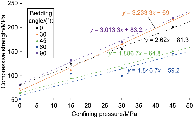
Fig. 1. Correlation between shale confining pressure and compressive strength. |
After the formation was drilled, the stress unloading occurs on the shale (Fig. 2a ). Based on the stress change, and taking a stress-strain curve of conventional triaxial experiment as a comparison (Fig. 2b ), we conducted triaxial experiments during stress unloading (Fig. 2c ): (1) Keeping the confining pressure constant and loading the axial stress to a fixed value; (2) Keeping the axial stress constant and unloading the confining pressure from point A to point B; and (3) After unloading process, restoring the confining pressure from point B to the original pressure at point C, and then loading the stress from point D to point E where the rock is failed. Consequentially, strength parameters of rock during unloading process were obtained. The unloading damage effect was confirmed by comparing with the compressive strength from a conventional triaxial experiment at the same confining pressure.
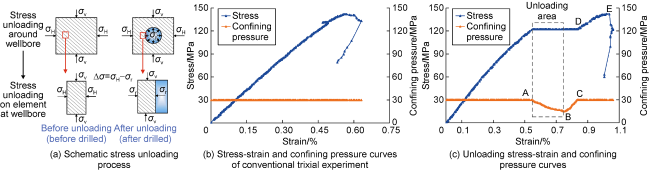
Fig. 2. Stress unloading experiments on shale formation. |
In the experiment, three confining pressures of 15, 25, 45 MPa were selected. Unloading ranges were set as 10%, 30%, 50% and 70% of each confining pressure, respectively. Based on the correlation between confining pressure and compressive strength in Fig. 1 , the compressive strength at each confining pressure was calculated, and values of 35%, 55% and 75% of compressive strength were taken as the axial stress. Multiple groups of experimental parameters were formed shown in Table 1 .
Table 1. Experimental parameters of stress unloading during drilling |
| No. | Confining pressure/ MPa | Axial stress | Unloading range | ||
|---|---|---|---|---|---|
| Value/ MPa | Proportion to compressive strength/% | Value/ MPa | Proportion to confining pressure/% | ||
| 1 | 15 | 42.21 | 35 | 1.5 | 10 |
| 2 | 90.45 | 75 | 1.5 | 10 | |
| 3 | 66.33 | 55 | 4.5 | 30 | |
| 4 | 42.21 | 35 | 7.5 | 50 | |
| 5 | 66.33 | 55 | 7.5 | 50 | |
| 6 | 42.21 | 35 | 10.5 | 70 | |
| 7 | 25 | 51.38 | 35 | 2.5 | 10 |
| 8 | 80.74 | 55 | 7.5 | 30 | |
| 9 | 51.38 | 35 | 12.5 | 50 | |
| 10 | 80.74 | 55 | 12.5 | 50 | |
| 11 | 51.38 | 35 | 17.5 | 70 | |
| 12 | 110.10 | 75 | 17.5 | 70 | |
| 13 | 45 | 69.72 | 35 | 4.5 | 10 |
| 14 | 69.72 | 35 | 13.5 | 30 | |
| 15 | 149.40 | 75 | 13.5 | 30 | |
| 16 | 69.72 | 35 | 22.5 | 50 | |
| 17 | 109.56 | 55 | 22.5 | 50 | |
| 18 | 149.40 | 75 | 31.5 | 70 | |
According to the theory of damage mechanics, the strength damage coefficient caused by stress unloading from drilling operation is shown in Eq. (1). The shale samples with 0° bedding angle were used to calculate and analyze the damage degree caused by stress unloading on shale strength (Fig. 3 ). It can be seen that, with increasing unloading range, the lateral supporting force decreases, and the damage caused by axial compression is enhanced. As a result, the weakening of compressive strength caused by stress unloading is stronger. Therefore, if the initial drilling fluid density is too low, high unloading range will trigger a strong unloading effect and weaken the wellbore stability, which is not conducive to the safety of following drilling operation. The influence of stress unloading on shale strength is closely related to the stress state. Under low confining pressure and low axial stress, the mechanical damage coefficient is low. The main reasons are as follows: At low confining pressure, the unloading stress variation is relatively small, and it is not easy to induce a significant strength decline. At small axial stress, the shale is in an elastic deformation stage, and the axial stress after unloading mainly causes elastic deformation, resulting in a small strength damage degree. At high confining pressure (e.g. 45.0 MPa) and high axial stress (149.4 MPa), compressive strength decreases more significantly after unloading, the damage coefficient is larger, and the impact of stress unloading is stronger.
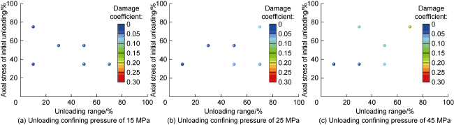
Fig. 3. Shale strength damage under unloading effect. |
Shale strength characteristics during stress unloading are closely related to the bedding occurrence. Bedding makes shale mechanical strength have significant anisotropy. With the change of bedding angle, both the angle between principal stress and bedding, and the angle between bedding and unloading direction change, leading to the modification of shale mechanical properties after stress unloading. In view of this, stress unloading experiments were conducted on shale samples with different bedding angles under a constant unloading condition (Fig. 4 ). When the bedding angle is 45° or 60°, shale has the strongest sensitivity to stress unloading, with the damage coefficient significantly higher than at other angles, indicating that shale is more likely to failure along the weak bedding plane. This is due to the small bearing capacity of the weak bedding plane. After the same stress unloaded, axial compression damage is stronger, and the strength decline is more obvious. It can be concluded that the joint effect of weak plane and unloading further weakens the mechanical stability of shale.
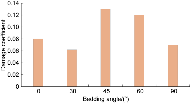
Fig. 4. Shale strength damamge during stress unloading on shale samples with different bedding angles. |
2. Influence of hydration on shale mechanical strength
The damage coefficient of bedding plane and matrix under hydration can be described as:
$\left\{\begin{array}{l} D_{\mathrm{hmc}}(t)=1-c_{\mathrm{m}}(t) / c_{\mathrm{mo}} \\ D_{\mathrm{hmi}}(t)=1-\varphi_{\mathrm{m}}(t) / \varphi_{\mathrm{mo}} \\ D_{\mathrm{hbc}}(t)=1-c_{\mathrm{b}}(t) / c_{\mathrm{bo}} \\ D_{\mathrm{hbi}}(t)=1-\varphi_{\mathrm{b}}(t) / \varphi_{\mathrm{bo}} \end{array}\right.$
Shear experiments along horizontal and vertical bedding can determine the strength characteristics of shale bedding and matrix, as well as the damage state of bedding and matrix in hydration process (Fig. 5 ). The experimental fluid is deionized water, and the shale samples (cylinders) have beddings with 0° and 90° angles. The experimental procedures are as follows: First, immersed the shale samples into the deionized water, and let them fully interact at 100 °C temperature and 3 MPa pressure difference to simulate the hydration process. After a certain interacting time, conducted shear experiments, first at constant vertical stress, then adding shear stresses along the bedding plane and perpendicular to the bedding plane until the sample was failed. The strength and damage characteristics were obtained. (1) It is observed that in the hydration process, the strength damages of bedding and matrix were not large in the early stage, and the cohesion was almost stable. After about 24 h, the cohesion decreased sharply and the bedding and matrix strengths had a strong decline. In the later stage, the cohesion gradually became stable. (2) The damage coefficients of bedding and matrix were low in the early stage and the rising rates were relatively small. The rising rate and range were large in the middle stage, and gradually tended to be stable in the late stage. Bedding is the plane with relatively high permeability, so that water phase is more likely to invade through bedding. Therefore, after the same action time of hydration, the cohesion and strength of bedding are lower than that of matrix. Meanwhile, with increasing hydration time, the damage coefficient rises faster and has a larger increment (Fig. 5a ). (3) In the hydration process, the changing trend of internal friction angle and damage coefficient are similar to that in Fig. 5a , showing that its decline is slow in the early stage, accelerated after about 24 h, and gradually stable in the later stage. (4) Water phase is more likely to invade bedding. In the hydration process, compared with matrix, the internal friction angle of bedding is smaller and its decline is stronger. The increase of its damage coefficient is larger (Fig. 5b ).
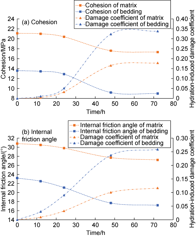
Fig. 5. Shale strength characteristics and damage coefficient after hydration effect. |
3. Shale wellbore stability model under the joint influence of stress unloading and hydration
3.1. Stress distribution around wellbore
According to the transverse isotropic stress distribution theory, the stress around wellbore in the rectangular coordinate system of shale formation with beddings is [15]:
$\left\{\begin{array}{l} \sigma_{x, \mathrm{~b}}=\sigma_{x, 0}+2 \operatorname{Re}\left[\mu_{1}^{2} \phi_{1}\left(Z_{1}\right)+\mu_{2}^{2} \phi_{2}\left(Z_{2}\right)+\mu_{3}^{2} \lambda_{3} \phi_{3}\left(Z_{3}\right)\right] \\ \sigma_{y, \mathrm{~b}}=\sigma_{y, 0}+2 \operatorname{Re}\left[\phi_{1}^{\prime}\left(Z_{1}\right)+\phi_{2}{ }^{\prime}\left(Z_{2}\right)+\lambda_{3} \phi_{3}^{\prime}\left(Z_{3}\right)\right] \\ \sigma_{z, \mathrm{~b}}=\sigma_{z, 0}-\frac{1}{a_{33}}\left(a_{31} \sigma_{x, \mathrm{~h}}+a_{32} \sigma_{y, \mathrm{~h}}+a_{34} \tau_{y z, \mathrm{~h}}+a_{35} \tau_{x z, \mathrm{~h}}+a_{36} \tau_{x y, \mathrm{~h}}\right) \\ \tau_{x y, \mathrm{~b}}=\tau_{x y, 0}-2 \operatorname{Re}\left[\mu_{1} \phi_{1}\left(Z_{1}\right)+\mu_{2} \phi_{2}\left(Z_{2}\right)+\mu_{3} \lambda_{3} \phi_{3}\left(Z_{3}\right)\right] \\ \tau_{x z, \mathrm{~b}}=\tau_{x z, 0}+2 \operatorname{Re}\left[\lambda_{1} \mu_{1} \phi_{1}\left(Z_{1}\right)+\lambda_{2} \mu_{2} \phi_{2}\left(Z_{2}\right)+\mu_{3} \phi_{3}\left(Z_{3}\right)\right] \\ \tau_{y z, \mathrm{~b}}=\tau_{y z, 0}-2 \operatorname{Re}\left[\lambda_{1} \phi_{1}\left(Z_{1}\right)+\lambda_{2} \phi_{2}\left(Z_{2}\right)+\phi_{3}\left(Z_{3}\right)\right] \end{array}\right.$
Based on above equations, the stress distribution in the borehole in cylindrical coordinate system can be obtained using spatial coordinate transformation method [16]:
$\left\{\begin{aligned} \sigma_{r}= & p_{\mathrm{w}}-\delta \phi\left(p_{\mathrm{w}}-p_{\mathrm{p}}\right) \\ \sigma_{\theta}=- & p_{\mathrm{w}}+\left(\sigma_{x, \mathrm{~b}}+\sigma_{y, \mathrm{~b}}\right)-2\left(\sigma_{x, \mathrm{~b}}-\sigma_{y, \mathrm{~b}}\right) \cos (2 \theta)- \\ & 4 \tau_{x y, \mathrm{~b}} \sin (2 \theta)+\delta\left[\frac{\alpha(1-2 v)}{1-v}-\phi\right]\left(p_{\mathrm{w}}-p_{\mathrm{p}}\right) \\ \sigma_{z}= & \sigma_{z, \mathrm{~b}}-2 v\left[\left(\sigma_{x, \mathrm{~b}}-\sigma_{y, \mathrm{~b}}\right) \cos (2 \theta)+2 \tau_{x y, \mathrm{~b}} \sin (2 \theta)\right]+ \\ & \delta\left[\frac{\alpha(1-2 v)}{1-v}-\phi\right]\left(p_{\mathrm{w}}-p_{\mathrm{p}}\right) \\ \tau_{\theta z}= & 2 \tau_{x y, \mathrm{~b}} \cos \theta-2 \tau_{x z, \mathrm{~b}} \sin \theta \\ \tau_{r \theta}= & \tau_{r z}=0 \end{aligned}\right.$
Based on the stress distribution around the wellbore, three principal stresses at any location in the wellbore can be determined, shown in Eq. (5). Then the maximum and minimum principal stresses can be determined.
$\left\{\begin{array}{l} \sigma_{i}=p_{\mathrm{w}}-\delta \phi\left(p_{\mathrm{w}}-p_{\mathrm{p}}\right) \\ \sigma_{j}=\frac{\sigma_{z}+\sigma_{\theta}}{2}+\sqrt{\left(\frac{\sigma_{\theta}-\sigma_{z}}{2}\right)^{2}+\tau_{\theta z}^{2}} \\ \sigma_{k}=\frac{\sigma_{z}+\sigma_{\theta}}{2}-\sqrt{\left(\frac{\sigma_{\theta}-\sigma_{z}}{2}\right)^{2}+\tau_{\theta z}^{2}} \end{array}\right.$
3.2. Distribution of unloading stress on wellbore
Before drilling, the stress state around the wellbore is mainly controlled by in-situ stress. Radial in-situ stress component is shown as Fig. 6a . After drilling, stress unloading is mainly created by the replacement of in-situ stress component by liquid column pressure in wellbore. Therefore, axial and circumferential stresses can be ignored. Radial stress change around wellbore after drilling is taken as the stress unloaded (Fig. 6b ). The expression is:
where
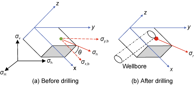
Fig. 6. Schematic of unloading stress around wellbore. |
3.3. Determination of wellbore instability
Based on the distribution of principal stress on wellbore, in order to clarify the wellbore instability in shale formation with beddings, it is necessary to determine the spatial location of principal stress, unloading direction and bedding plane. The angle between the maximum principal stress and axial z is [17]:
The angle between the maximum principal stress and the normal direction of bedding plane is:
where n is determined by the dip angle and strike of the bedding plane:
N is controlled by circumferential angle, well inclination angle, azimuth angle, and the angle between the maximum principal stress and axis z, and expressed as:
$\left\{\begin{array}{l} \boldsymbol{N}=b_{1} \boldsymbol{i}+b_{2} \boldsymbol{j}+b_{3} \boldsymbol{k} \\ b_{1}=\cos b \cos a \sin \theta-\sin b \cos \theta+\cos b \sin a \cos \gamma \\ b_{2}=\sin b \cos a \sin \theta+\cos b \cos \theta+\sin b \sin a \cos \gamma \\ b_{3}=-\sin a \sin \theta+\cos a \cos \gamma \end{array}\right.$
Since the unloading direction is located at the wellbore plane, the angle between the unloading direction and the normal direction of bedding can be obtained according to the same conversion method. The unloading damage coefficient is controlled by bedding angle, unloading direction, initial unloading confining pressure, unloading axial stress and unloading stress variation. According to damage mechanics theory, in combination with drilling stress unloading and hydration, the coupling equation of two types of damages can be expressed as [18]:
According to the damage coefficient and single weak plane criterion, under the combined action of stress unloading and hydration, critical failure equations of shale matrix (Eq. (12)) and bedding (Eq. (13)) can be obtained:
Based on the mechanical experimental data and shale failure criteria, shale strength at different drilling time can be obtained (Fig. 7 ). In the early drilling stage (24 h), the compressive strength after unloading is lower than that after hydration, indicating that the unloading damage is greater than hydration damage. In the late drilling stage (after 48 h and 72 h), hydration damage is aggravated, and has a more significant impact on shale strength. In addition, after the same drilling time, the compressive strength after stress unloading + hydration is the smallest, indicating that the joint action of stress unloading + hydration aggravates the wellbore instability.
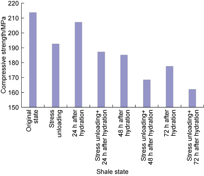
Fig. 7. Influence of stress unloading and hydration on shale strength after different drilling hours. |
To sum up, the calculation process of wellbore stability model considering the combined action of stress unloading and hydration is shown in Fig. 8 . Firstly, stress distribution around wellbore after drilling is determined to obtain the unloading stress variation, unloading confining pressure and unloading axial stress. Then, rock strength and failure type around the wellbore after unloading are determined. Collapse pressure after drilling is calculated, and the initial drilling fluid density is estimated. On this basis, considering the damage law of shale strength under the combined action of stress unloading and hydration, the collapse pressure in shale formation at any drilling time is obtained.
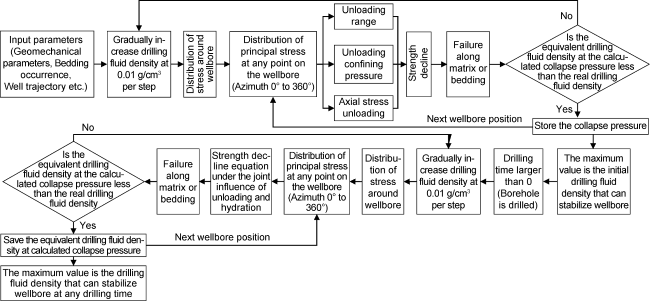
Fig. 8. Flow chart of calculating collapse pressure and equivalent drilling fluid density at any drilling time under the joint action of stress unloading and hydration. |
4. Analysis of wellbore stability
Based on the shale wellbore stability model, wellbore stability analysis has been conducted. The mechanical parameters of shale formation are based on previous mechanical experiment data. Other calculated parameters are as follows: 3153 m well depth, 19.8° bedding angle, 116.5° bedding azimuth, 2.31 g/cm3 equivalent drilling fluid density at vertical stress, 2.28 g/cm3 and 1.95 g/cm3 equivalent drilling fluid density at the maximum and minimum horizontal principal stresses, respectively, 1.15 g/cm3 equivalent drilling fluid density at pore pressure, 3.2% porosity and 0.85 Biot coefficient. Ignoring hydration and only considering drilling stress unloading, the influence of unloading on collapse pressure in different formation structures was analyzed (Fig. 9 ). Under homogeneous condition, the collapse pressure is low and symmetrically distributed. The equivalent drilling fluid density at collapse pressure is mainly 1.00-1.20 g/cm3, and the increment of collapse pressure caused by unloading is relatively small. Compared with homogeneous condition, considering weak bedding plane, the collapse pressure increases significantly, and the equivalent density at collapse pressure is mainly 1.15-1.55 g/cm3, and no longer symmetrical distribution. With bedding plane, the increment of collapse pressure caused by unloading is larger than that under homogeneous condition (change in the colormap is more obvious). Weak bedding is more sensitive to stress unloading. Under different bedding dip angle and bedding azimuth conditions, the relative positions of unloading direction, bedding direction and principal stress at the wall of borehole change due to the difference of intersection position between wellbore and bedding. Whether there is drilling stress unloading or not, the distribution of collapse pressure changes significantly, indicating that borehole trajectory and bedding occurrence are key factors on wellbore stability.
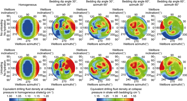
Fig. 9. The influence of stress unloading under different bedding characteristics on equivalent drilling fluid density at collapse pressure. |
The model presented in this paper is used to analyze the collapse pressure distribution in shale formation under the joint action of stress unloading and hydration (Fig. 10 ). It can be seen that, compared with homogeneity formation, higher collapse pressure exists in the formation with rich beddings because bedding is a weak and relatively high permeable plane, it is more sensitive to stress unloading, whether unloading is considered or not. The increment of collapse pressure caused by stress unloading on bedded formation is larger. With the increase of drilling time, hydration effect on bedded formation becomes stronger, and the collapse pressure increases accordingly. Compared with the mechanical-chemical coupling shale model (considering hydration, but no unloading), collapse pressure increases with unloading effect, weakening shale wellbore stability. In the early drilling stage (after 24 h), the increment of collapse pressure caused by stress unloading is more obvious. With increasing drilling time, the damage caused by hydration is gradually serious. In the late drilling stage, the collapse pressure caused by hydration increases more significantly than that caused by unloading, indicating the influence of hydration on the collapse pressure gradually takes a dominant position.
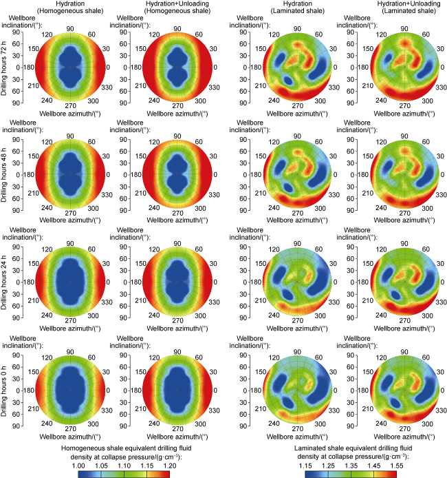
Fig. 10. Equivalent drilling fluid density at collapse pressure under the joint influence of stress unloading and hydration. |
To sum up, bedding, unloading and hydration are all important factors affecting the stability of shale wellbore. Based on a layered medium, a reasonable and optimal design of shale drilling engineering can be achieved by combining influences of stress unloading and hydration. In the whole drilling process, the joint action of stress unloading and hydration must be considered when selecting drilling fluid density.
5. Field application
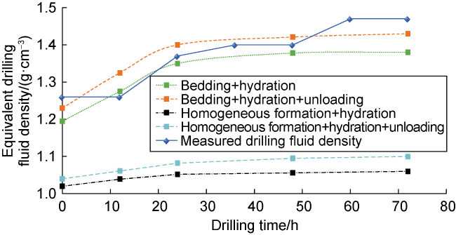
Well G204 in the Changning area was chosen as a case. The vertical depth of the shale reservoir in the Longmaxi Formation is 3315 m; the equivalent drilling fluid density at pore pressure is 1.08 g/cm3; the equivalent drilling fluid density at vertical in-situ stress is 2.24 g/cm3; and the maximum and minimum horizontal principal stresses are 2.19 g/cm3 and 1.89 g/cm3, respectively. The well inclination and azimuth are 88.5° and 114.3° respectively, the bedding dip and azimuth are 25.4° and 102.6° respectively. The initial drilling fluid density is 1.26g/cm3, and the wellbore was stable in the early drilling stage, but collapsed later. Then the drilling fluid density was gradually increased, but wellbore collapse was still obvious after increasing two times until when the density was increased to 1.47g /cm3. Based on the basic data and the predicted collapse pressure in the drilling process (Fig. 11 ), it is concluded that, (1) under homogeneous condition, the shale collapse pressure predicted is significantly lower whether the influence of stress unloading is taken into account or not. (2) Considering bedding plane and hydration, and ignoring the influence of stress unloading, the predicted collapse pressure is in agreement with the measured, but it is lower. (3) Considering the influence of bedding plane, hydration and stress unloading, the predicted collapse pressure is in good agreement with the measured, which proves the accuracy of our model.
Fig. 11. Appplication of the wellbore stability model in Well G204. |
6. Conclusions
Stress unloading occurs with drilling. With larger confining pressure and axial stress, shale strength may largely decline with stress unloading. The range of stress unloading is positively correlated with the weakened degree of the mechanical strength of shale.
The more developed shale bedding is, the easier the damage occurs along bedding. During stress unloading, weak structural plane and stress unloading act simultaneously, causing a higher degree of strength decline, worse mechanical stability and larger risk of wellbore instability. External fluid is easy to invade along the bedding, promoting shale hydration, which also worsens the mechanical stability of shale and reduces the wellbore stability. The influence of stress unloading on shale collapse pressure mainly occurs in early drilling operation, and the influence of hydration damage on wellbore instability mainly occurs in late drilling stage.
Bedding, stress unloading and hydration affect shale wellbore stability. The model of wellbore stability under the joint action of stress unloading and hydration takes these three influence factors into consideration. The field application shows that the predicted results are in good agreement with the practical drilling condition, proving the model has a good reliability.
Nomenclature
a—wellbore inclination, (°);
aw—bedding azimuth, (°);
a31, a32, a33, a34, a35, a36—flexibility matrix coefficients of transversely isotropic medium, dimensionless;
b—borehole azimuth, (°);
b1, b2, b3—modulus at direction i, j, k respectively, dimensionless;
bw—bedding dip, (°);
cbo, cb(t)—cohesion of original shale bedding and that of shale bedding during hydration, MPa;
cmo, cm(t)—cohesion of original matrix and that of matrix during hydration, MPa;
D—damage coefficient, dimensionless;
Du—damage coefficient caused by unloading, dimensionless;
Dh(t), Dhmc(t), Dhmi(t)—hydration damage coefficients of shale, matrix cohesion and matrix internal friction angle at time t, dimensionless;
Dhbc(t), Dhbi(t)—hydration damage coefficients of bedding cohesion and bedding internal friction angle at time, dimensionless;
i, j, k—unit vectors in the directions of the Cartesian axis;
n—normal vector of bedding;
N—vector along the maximum principal stress on wellbore;
pp—pore pressure, MPa;
pw—liquid column pressure, MPa;
Re—the real part of a complex number;
x, y, z—rectangular coordinate system, m;
z1, z2, z3—complex variables;
α—Biot coefficient, dimensionless;
βw—included angle of maximum principal stress and bedding, (°);
βuw—included angle of principal stress and unloading direction, (°);
βo—included angle of failed matrix plane and maximum principal stress, (°);
γ—included angle of maximum principal stress and axial direction, (°);
δ—permeability coefficient of wellbore, dimensionless;
θ—circumferential angle, (°);
λ1, λ2, λ3—ratio of characteristic roots, dimensionless;
μ1, μ2, μ3—characteristic roots of characteristic equation corresponded to strain coordination equation, dimensionless;
ν—Poisson’s ratio, dimensionless;
σ1, σ3—maximum and minimum principal stresses, MPa;
σc—compressive strength of original shale, MPa;
σcu—compressive strength after stress unloading, MPa;
σi, σj, σk—three principal stresses on the wellbore, MPa;
σn—component of in-situ stress along unloading direction, MPa;
σv, σH, σh—vertical, maximum and minimum horizontal principal stress, MPa;
σr, σz, σθ—radial stress, stress along z-axis, circumferential stress at cylindrical coordinate system, MPa;
τrz, τθz, τrθ—shear stress tangent to planes rz, θz, rz at cylindrical coordinate system, MPa;
σx,b, σy,b, σz,b—stress around wellbore in laminated formation along x-axis, y-axis, z-axis, MPa;
τxy,b, τyz,b, τxz,b—shear stress around wellbore tangent to planes xy, yz, xz in laminated formation, MPa;
σx,o, σy,o, σz,o—stress around wellbore at in-situ stress along x-axis, y-axis, z-axis, MPa;
τxy,o, τyz,o, τxz,o—shear stress around wellbore tangent to planes xy, yz, xz at in-situ stress, MPa;
σx,h, σy,h—boundary stresses along x-axis, y-axis of the wellbore after drilling, MPa;
τxy,h, τyz,h, τxz,h—boundary stresses tangent to planes xy, yz, xz along the wellbore after drilling, MPa;
Δσ—unloading stress variation, MPa;
ϕ—porosity, %;
ϕ1, ϕ2, ϕ3—analytic functions of transversely isotropic equation;
φbo, φb(t)—internal friction angle of original bedding plane and that of the bedding plane after hydration, (°);
φmo, φm(t)—internal friction angle of original shale matrix and that of the shale matrix after hydration, (°).