

Introduction
China is abundant in tight oil reserves, which play the important role of increasing reserves and production [1-2]. High-efficient development of tight oil is a difficult issue for the global oil industry. Tight oil reservoirs in China have the typical characteristics of multi-stage fracture development, poor fluidity and low-pressure coefficient [3⇓-5]. In order to maintain the formation energy, the rhombic inverted nine-spot vertical well pattern and five-spot or seven-spot horizontal well patterns are mainly used for water injection development [6⇓⇓-9]. However, the overall performance is characterized by the rapid water cut increase and pressure drop, with an initial decline of more than 30%. The conventional water drive adjustment technology has poor adaptability and the effective rate is only 26%. In some tight oil reservoirs, the oil production rate is only 0.2%, and the recovery factor is only 5%-8%, which is 8 percentage points to 10 percentage points lower than the calibrated recovery factor. It is urgent to explore a new development model that can greatly improve the recovery factor.
Tight oil reservoir needs fracturing to form the flow channels and energy replenish through water injection for effective oil production. During the water injection development, the water channeling in fracture is easy to happen, which aggravates the heterogeneity of reservoir and fluid flow [10⇓⇓⇓-14]. The matching of fracture network and the utilization of fractures through the whole life cycle of development should be considered, and only the rational utilization of fractures can greatly improve the oil recovery. The characterization and fine simulation of fractures have become the crucial issue to optimize development plan, reduce development risk and improve oil recovery. The key issue to predict the production performance of tight oil reservoirs after the large-scale fracturing is to simulate the coupling effect of in-situ stress and seepage fields and the geometry of fractures. The coupling model of in-situ stress and seepage fields was first put forward by Settari and other scholars [15]. Under the constraint of elastic mechanics theory, the seepage and geomechanics equations are coupled through the strict equation terms, and the model satisfies the conservation of energy and mass at the same time. The model has more rigorous mathematical expression and higher model accuracy. Aiming at the geometric simulation of fractures, a large number of scholars focus on the spatial discretization method. Based on the generated fracture parameter distribution, the embedded discrete fracture model (EDFM), discrete fracture model (DFM) or continuous fracture model (CF) can be used to integrate fracture information in the model and simulate fracture flow [16]. Among them, the EDFM and DFM can completely describe the shape of large-scale artificial fractures with better simulation effects. However, the EDFM uses virtual fracture slices to describe the geometric shape of fractures, which avoids the complicated mesh generation process in the DFM and has more industrial application prospects.
Based on the theory of pore elasticity and EDFM, this paper constructs an embedded fracture flow model coupled with the seepage and geomechanics, and puts forward a solution strategy based on the fixed stress iteration method. Based on the reconstructed in-situ stress field, seepage and pressure fields, through the fine numerical simulation of fractures, the energy evolution law in tight oil reservoirs after long-term water injection is analyzed. Moreover, the technology of multi-field reconstruction and combined displacement-imbibition for enhancing tight oil recovery is put forward. Finally, the feasibility of the technology is verified by the practice in the oilfield.
1. The fracture flow model of seepage-geomechanics coupling in tight oil reservoir
In order to characterize the changes of stress, seepage and energy fields in tight oil reservoir after the long-term water injection development, a fracture flow model coupled with seepage and geomechanics is established. It considers the flow and phase change process of the multi-component fluid and the fluid-solid coupling process in reservoir under geomechanics effect and the mechanical behavior of fractures. In order to ensure the calculation efficiency, we designed a simulation framework based on the iterative coupling solution method of fixed stress. The models of geomechanics, seepage and fracture can be combined organically. Compared with the traditional model, this method can quantify the influence of in-situ stress and fracture on tight oil reservoir flow. Moreover, the model provides quantitative basis for evaluating and reconstructing the fields of stress, seepage and energy.
1.1. Seepage equation coupled with the geomechanical effect in reservoir
Hypothesis: the fluid is slightly compressible; rocks only undergo the linear elastic deformation; the mechanical process is a quasi-static process; the deformation of rock satisfies the assumption of small deformation; the production process is under constant temperature with no chemical reaction. The geomechanical equation of reservoir can be established as follows:
$\left\{ \begin{align} & \nabla \cdot \left( {{C}_{dr}}:\varepsilon -b{{p}_{\text{E}}}\delta \right)\text{+}\left[ \varphi {{\rho }_{\text{f}}}\text{+}\left( 1-\varphi \right){{\rho }_{\text{s}}} \right]g=0 \\ & \varepsilon =\frac{1}{2}\left( \nabla u+{{\left( \nabla u \right)}^{T}} \right) \\ \end{align} \right.$
where
${{p}_{E}}\text{=}{{S}_{w}}{{p}_{w}}+{{S}_{\text{o}}}{{p}_{o}}+{{S}_{\text{g}}}{{p}_{g}}$${{\rho }_{\text{f}}}\text{=}{{S}_{w}}{{\rho }_{w}}+{{S}_{\text{o}}}{{\rho }_{o}}+{{S}_{\text{g}}}{{\rho }_{g}}$
Based on the theory of conservation of mass and Darcy's flow law, the flow control equations of carbon component i and water considering rock deformation are respectively:
$\frac{\partial \left[ \left( {{x}_{i}}{{S}_{o}}{{\rho }_{o}}+{{y}_{i}}{{S}_{g}}{{\rho }_{g}} \right)\phi \right]}{\partial t}\text{+}\frac{\left[ \left( {{x}_{i}}{{S}_{o}}{{\rho }_{o}}+{{y}_{i}}{{S}_{g}}{{\rho }_{g}} \right)\phi \right]\partial {{\varepsilon }_{v}}}{\partial t}\text{=}$
$\nabla \cdot \left[ {{x}_{i}}\frac{{{\rho }_{o}}{{K}_{ro}}}{{{\mu }_{o}}}K\left( \nabla {{p}_{o}}-{{\rho }_{o}}g \right)+{{y}_{i}}\frac{{{\rho }_{g}}{{K}_{rg}}}{{{\mu }_{g}}}K\left( \nabla {{p}_{g}}-{{\rho }_{g}}g \right) \right]-{{q}_{i}}$
(i=1, 2, …, nc)
$\frac{\partial \left( {{S}_{w}}{{\rho }_{w}}\phi \right)}{\partial t}+\frac{\left( {{S}_{w}}{{\rho }_{w}}\phi \right)\partial {{\varepsilon }_{v}}}{\partial t}\text{=}\nabla \cdot \left[ \frac{{{\rho }_{w}}{{K}_{rw}}}{{{\mu }_{w}}}K\left( \nabla {{p}_{w}}-{{\rho }_{w}}g \right) \right]-{{q}_{w}}$
The fugacity equilibrium equation of each carbon component is constructed to constrain the variables, namely:
${{f}_{\text{L},i}}-{{f}_{\text{V},i}}=0$
Additionally, the molar fraction and saturation should satisfy the following linear constraints:
$\sum\limits_{i=1}^{{{n}_{\text{c}}}}{{{x}_{i}}}-1=0$
$\sum\limits_{i=1}^{{{n}_{\text{c}}}}{{{y}_{i}}}-1=0$
${{S}_{w}}+{{S}_{g}}+{{S}_{\mathrm{o}}}=1$
1.2. Fracture model
The fracture model includes the calculation models of fracture deformation and fracture constitutive relation. The displacement discontinuity method (DDM) is used to calculate the real deformation of fractures, in which the variables to be solved are set as normal displacement (Dn) and tangential displacement (Ds). When solving the equations, the mesh generation is conducted first for all fractures in the space. For two-dimensional equations, they are divided into a series of line elements. The normal and tangential displacements of each element are defined based on the local coordinate system O-xy of the element:
$\left\{ \begin{align} & {{D}_{\text{s}}}={{u}_{x}}\text{ }\left( x,{{0}_{-}} \right)-{{u}_{x}}\text{ }\left( x,{{0}_{+}} \right) \\ & {{D}_{\text{n}}}={{u}_{y}}\text{ }\left( x,{{0}_{-}} \right)-{{u}_{y}}\text{ }\left( x,{{0}_{+}} \right) \\ \end{align} \right.$
Under the above definition, the displacement discontinuity induced by the element at any point in the space is expressed as:
$\left\{ \begin{align} & {{u}_{x}}=\left[ 2\left( 1-\upsilon \right){{f}_{y}}-y{{f}_{xx}} \right]+\left[ -\left( 1-2\upsilon \right){{g}_{x}}-y{{g}_{xy}} \right] \\ & {{u}_{y}}=\left[ \left( 1-2\upsilon \right){{f}_{x}}-y{{f}_{xy}} \right]+\left[ 2\left( 1-\upsilon \right){{g}_{y}}-y{{g}_{yy}} \right] \\ & {{\sigma }_{xx}}=2G\left( 2{{f}_{xy}}+y{{f}_{xyy}} \right)+2G\left( {{g}_{yy}}+y{{g}_{yyy}} \right) \\ & {{\sigma }_{yy}}=2G\left( -y{{f}_{xyy}} \right)+2G\left( {{g}_{yy}}-y{{g}_{yyy}} \right) \\ & {{\tau }_{xy}}=2G\left( 2{{f}_{yy}}+y{{f}_{yyy}} \right)+2G\left( -y{{g}_{xyy}} \right) \\ \end{align} \right.$
In the fracture element, the local conservation of fluid is controlled by the mass balance equation, which can be expressed as:
$\frac{\partial \left( q\overline{w} \right)}{\partial s}+\frac{\partial \left( \overline{w} \right)}{\partial t}+{{q}_{\text{L}}}=0$
${{\mathsf{q}}_{\text{L}}}=\frac{2{{C}_{\text{L}}}}{\sqrt{t-{{t}_{\mathrm{0}}}}}$
Additionally, the fluid also needs to satisfy the law of global volume conservation:
$\int_{\mathrm{0}}^{\mathsf{t}}{Q\left( \mathsf{t} \right)dt}=\int\limits_{{{\mathsf{H}}_{\text{fl}}}}{\int_{\mathrm{0}}^{\mathsf{L}\left( \mathsf{t} \right)}{\overline{w}d\mathsf{s}}}d\mathsf{h}+\int\limits_{{{\mathsf{H}}_{\text{fl}}}}{\int_{\mathrm{0}}^{\mathsf{L}\left( \mathsf{t} \right)}{\int_{\mathrm{0}}^{\mathsf{t}}{{{q}_{\text{L}}}}d\mathsf{t}d\mathsf{s}}}d\mathsf{h}$
The constitutive model of fractures is constructed by Barton-Bandis model [17], and the constitutive relationship is described by the flexibility model, which is a diagonal matrix composed of normal stiffness (Kn) and tangential stiffness (Ks):
$C\text{=diag}\left( \frac{1}{K_{n}^{{}}},\frac{1}{K_{\text{s}}^{{}}},\frac{1}{K_{\text{s}}^{{}}} \right)$
1.3. Spatial discretization and solution methods
The EDFM is used to simulate the influence of fracture geometry on the flow. For solving geomechanical equations, the Oda method [18] is used in morphology processing for EDFM equivalently. For solving fluid flow equations, the EDFM embeds fractures into matrix grids as extra grids, and the flow communication relationship of fractures is processed by introducing non-neighbor connection (NNC). Fig. 1 is shown for the information of 3 types of NNC.
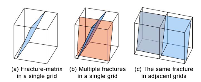
Fig. 1 Three types of NNC in EDFM (the grid in the figure is matrix grid, and the blue and orange surfaces are fracture slices). |
In this paper, the Karmi-Fard method is used to calculate the conductivity:
$T={K{{A}_{\text{n}}}}/{{{d}_{\text{n}}}}\;$
For the first type of NNC, the characteristic area (An) is the intersection area of fracture and grid; the permeability (K) is the harmonic average of matrix permeability and fracture permeability, and the characteristic distance (dn) is the function of unit-control volume and unit volume:
${{d}_{\text{n}}}\text{=}\frac{\int_{{{V}_{\text{c}}}}{d}dV}{{{V}_{\text{c}}}}$
For type 2 and type 3 of NNC, the conductivity is the harmonic average of two fracture slices, in which the conductivity of a single fracture slice can be expressed as a function of fracture width, fracture intersection length and center distance between fracture slices:
${{T}_{f}}=\frac{{{K}_{f}}{{w}_{f}}{{L}_{\operatorname{int}}}}{{{d}_{f}}}$
The geomechanics-seepage coupling simulation is carried out by the fixed stress iterative coupling method, and fracture system is simulated by the explicit coupling method. In the process of solving, the requirements of variable convergence and numerical stability are fully considered, and the geomechanical equation is discretized by the finite element method. The fluid flow equation is discretized by the finite difference method, and the fracture propagation equation is discretized by the DDM. The simulation process is shown in Fig. 2 . In the process of solving, due to the advantage of embedded discrete fractures, there is no need to re-subdivide the background grid. However, only the fracture morphology needs to be updated and the connectivity between the fracture and the matrix grid needs to be recalculated, which greatly saves calculating time. In the initialization part, the gravity balance method is used to initialize the fluid pressure field, and then the initial in-situ stress field is calculated accordingly. The simulation result of the previous time step is directly substituted to solve the reset problem. The whole fluid-solid coupling process is solved at the same time step. After solving the fluid-solid coupling process, the fracture shapes and parameters are updated according to the current in-situ stress state of the grid, and whether it is necessary to update the fracture grid at the current time step can be decided.
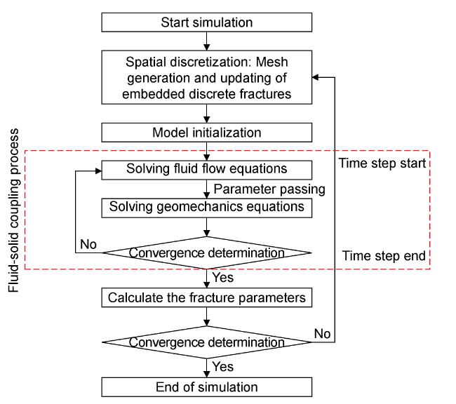
Fig. 2 Numerical simulation flow chart. |
2. Fracture flow model verification
2.1. Model building
Taking the Block Yuan 284 of Huaqing Oilfield in the Ordos Basin, NW China, as an example, based on the geological conditions and production data of the work area, the numerical simulation is carried out by using the model in this paper to verify its reliability and accuracy. The development stratum in this block is the first sublayer of the third submember of the sixth member of Triassic Yanchang Formation (Chang 631), with an effective thickness of 21.2 m, an average porosity of 12% and an average permeability of 0.37×10⁻³ μm2. The vertical principal stress, maximum horizontal principal stress and minimum horizontal principal stress is 55.0, 42.0 and 36.8 MPa, respectively. According to the requirements of simulation calculation, the simulation range is 2 700 m × 2 000 m, including 3 horizontal production wells and 14 vertical water injection wells. The model grid size is 20 m× 20 m× 2 m.
2.2. Model verification
Well CP52-10 has a depth of about 3 100 m and a horizontal section length of about 1 100 m. The hydraulic fracturing technology is adopted for reservoir stimulation. The number of fracturing stages is 12, with an average construction fluid volume of about 160 m3 and an average proppant consumption of about 27.5 m3, with simple two-wing fracture propagation dominantly. Based on the physical parameters, mechanical parameters and fracturing scheme of the actual reservoir, the proposed model is used to simulate the fracture shapes in this well to obtain the fracture shape and conductivity after the first fracturing. The simulated fracture length in Well CP52-10 is about 80-120 m, the fracture height is about 15-24 m, and the fracture permeability is about (150-580) × 10−3 μm2. The model is debugged by means of constant production fitting pressure, and the production is predicted by means of constant pressure. Fig. 3 shows the historical fitting effect of daily oil production and bottom hole flowing pressure of Well CP52-10. It can be seen that the early production declines rapidly, while the later production is stable. Compared with the actual production data, the prediction error of the model is less than 5%.
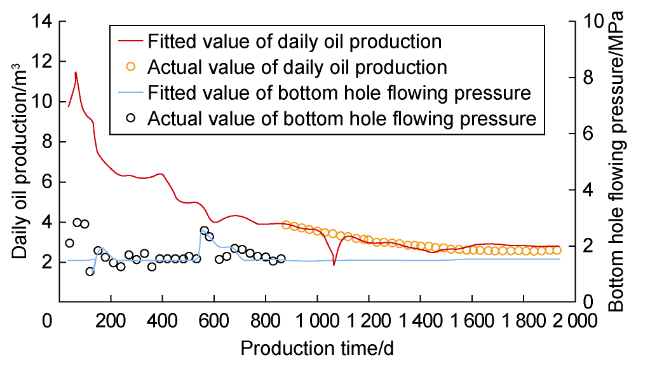
Fig. 3 History fitting results in Well CP52-10. |
3. Changes of pressure, seepage and stress fields in tight oil reservoir after long-term water injection development
3.1. Variation law of pressure and seepage fields
Under the water injection development with traditional well pattern, affected by the physical properties of tight oil reservoir, the pressure diffusion range is small. The energy supplement efficiency of water injection wells is low, and the energy transmission speed is slow. After 400 d of simulated water injection development, it can be seen from the pressure field distribution diagram (Fig. 4 ) that the bottom hole pressure of water injection well is still maintained at the peak value. The pressure diffusion radius is 36-60 m, the pressure near the production well is as low as 5-10 MPa. The pressure drop along the wellbore is uneven, and there is residual oil between sections. The streamline between water injection and production wells are sparse mostly, and the effective displacement system cannot be formed (Fig. 5 ). The phenomenon shows that the water injection development failed to establish effective displacement system in tight oil reservoir, and the energy could not be effectively diffused in the reservoir, resulting in unbalanced pressure distribution after the long-term production.
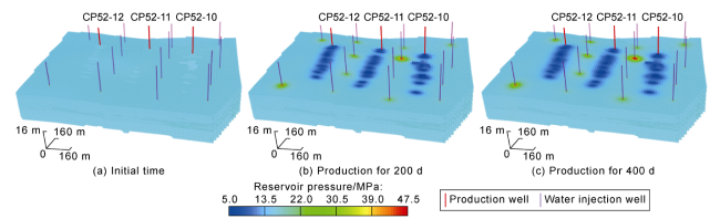
Fig. 4 Pressure field distribution at different times after water injection development of wells CP52-10, CP52-11, CP52-12 in Block Yuan 284. |
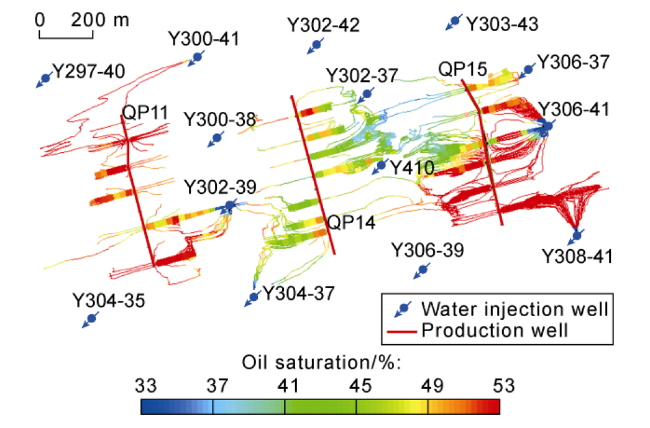
Fig. 5 Distribution of seepage field after water injection development of wells QP11,QP14, QP15 in Block Yuan 284. |
3.2. Stress field change law
In-situ stress distribution is the key factor affecting the effect of reservoir stimulation. The simulation results show that the long-term water injection development has a significant impact on the reservoir stress field. The variation amplitude of different principal stresses is different, and the long-term water injection will cause the deflection of local in-situ stress orientation.
Comparing the three-dimensional stress changes before and after long-term water injection development (Fig. 6 ), it can be found that the in-situ stress changes with the change of reservoir fluid pressure. In the horizontal direction, due to the influence of fluid transient effect, the mechanical balance cannot reach quasi-static, which leads to the decrease of the minimum principal stress around the production well greater than that of the maximum principal stress with the increase of produced liquid volume (Fig. 7 ).

Fig. 6 Distribution of horizontal in-situ stress field before and after water injection development. |
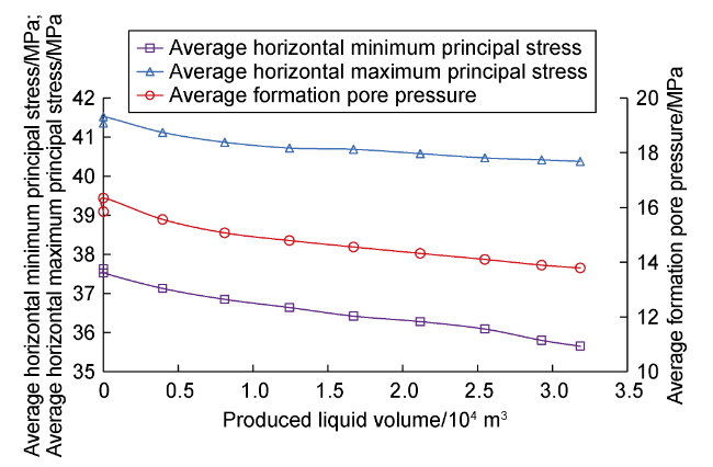
Fig. 7 Variation of reservoir stress with produced liquid volume. |
The direction of in-situ stress is controlled by the thermodynamic properties of porous media, fracture development and pressure gradient, and the long-term water injection development leads to the deflection of in-situ stress orientation. For oil production and water injection wells, the stress steering mechanism and effect are quite different. The stress steering in production wells mainly occurs after fracturing, and the main reason is that fracturing fractures can change the mechanical properties of reservoirs. The rocks close to the fractures undergo extrusion deformation, and those between fracturing fractures undergo expansion deformation, which causes the in-situ stress steering along the periphery of fractures. After fracturing, the in-situ stress has a steering amplitude of 0 to 10°, and that becomes 0 to 0.13° after water injection development (Fig. 8 ).
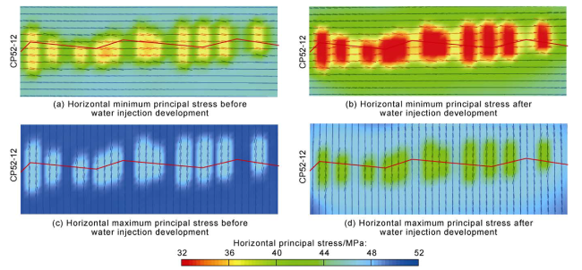
Fig. 8 Distribution of in-situ stress around production wells before and after water injection development (the line direction in the figure represents stress direction). |
The in-situ stress around the water injection well has large steering amplitude, and the maximum amplitude can reach 40° (Fig. 9 ). The in-situ stress is centered on the water injection well and distributed radially. The distribution of horizontal maximum principal stress is convergent, and that of horizontal minimum principal stress is radial. With the development of water injection, the pore pressure gradient first increases and then decreases, and the influenced radius of in-situ stress steering gradually expands, and the steering angle around the water injection well first increases and then decreases, and finally reaches stability. After the stress is stabilized, the in-situ stress around the water injection well still keeps a steering angle of 0-30°. The change of pore pressure gradient is the main reason for the stress steering of reservoir around the water injection well.
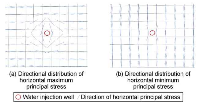
Fig. 9 Distribution of in-situ stress around water injection well when the pore pressure gradient is the maximum. |
4. Multi-field reconstruction and combined displacement-imbibition EOR technology and key parameter optimization
Based on the quantitative evaluation of the dynamic change of the flow field and the changing laws of the pressure, seepage and stress fields in tight oil reservoir with the long-term water injection development, this paper puts forward the technology of enhancing oil recovery by multi-field reconstruction and combined displacement-imbibition: (1) Reconstructing the artificial volume fracture network system and establishing multiple coupled flow modes such as horizontal flow and longitudinal flow in vertical fractures; (2) Making full use of the change law of in-situ stress field. Reconstructing the reservoir energy field, improving the complexity of fractures, and increasing the utilization degree of reserves through water injection before fracturing and fracturing to enhance energy; (3) Enhancing imbibition effect through multi-well linkage, reconstructing the combination system of displacement and imbibition under complex fracture network, and changing the mode from avoiding fractures to using fractures, so as to improve the micro-sweep efficiency and oil displacement efficiency.
4.1. Reconstruction of the in-situ stress field by water injection before fracturing
The mechanism of replenishing energy before fracturing is to improve the stress balance and fracbility of reservoir by injecting liquid on a large scale, and then enhance the complexity of fractures. Pressure rise effectively reconstructs the stress field of reservoir and provides sufficient conditions for repeated fracturing to form complex fracture network. The liquid volume in new and old fractures is set at 1 000 m3 and 1 200 m3 respectively, and the amount of injected sand is set at 30 m3. Taking the pressure field and in-situ stress field formed by injecting different times of the produced liquid volume (0.5, 0.8, 1.0 and 1.2 times) as initial conditions, the fracturing simulation is carried out, and the influence of the injected liquid volume before fracturing on the fracturing effect is analyzed.
It can be seen from the stress field after energy replenishment before fracturing (Fig. 10 ) that the in-situ stress in the fracture area is greatly increased. Due to the short injection period and the transient effect of fluid, the reconstruction of reservoir energy field by energy replenishment before fracturing is mainly concentrated in the near-well zone, so as to improve the fracturing effect. The in-situ stress in the near-well zone can be restored to the original level by energy replenishment before fracturing with liquid volume above 1.0 times the produced liquid volume. With the increasing liquid volume for energy replenishment before fracturing, the improvement degree of single well fracturing effect is increased (Fig. 11 ). The optimal liquid volume for energy replenishment before fracturing is 1.0 times the produced liquid volume. If continuously increase the liquid volume for energy replenishment before fracturing, the fracturing improvement degree will be decreased.
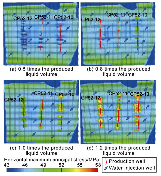
Fig. 10 Numerical simulation results of reservoir stress field after water injection and energy replenishment before fracturing. |
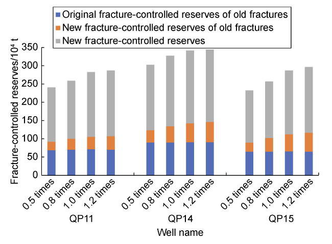
Fig. 11 Numerical simulation results of fracturing to improve reservoir energy field (0.5 times means that the injected liquid volume before fracturing is 0.5 times the produced liquid volume, and the rest are the same). |
4.2. Volume fracturing well pattern and energized re-fracturing to reconstruct the energy field
The traditional well pattern has low efficiency, and the seepage mode is mainly plane radial flow. In order to break through the limitation of plane radial flow in traditional water injection well pattern, a flexible well pattern without distinction in well types is designed. The water injection wells are converted to production, and the volume fracturing technology is adopted to reconstruct the fracture field of converted production wells and horizontal wells. Complex fracture network can improve the flow ability around the well and quickly replenish the formation energy. The seepage changes from one-way linear flow to unstable flow, and the horizontal flow and longitudinal flow in vertical fractures are coupled, which changes the reservoir seepage mode into flowing in complex fracture network and greatly increases the swept volume.
Through the numerical simulation, the development effect of standard example under the constant pressure in flexible well pattern is compared with that of traditional well pattern (Fig. 12 ). In the traditional well pattern, the pressure transmission is slow, and the oil drainage area is about 4.3×10⁵ m2. However, in the flexible well pattern, a large-scale fracture network system is formed, and the oil drainage area is 3.5×10⁶ m2.
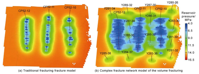
Fig. 12 Influence of different fracturing models on pressure transmission. |
In the process of fracturing, the optimization of the fracturing fluid injected in the reservoir is also critical. In the actual construction, the priority is densifying the fractures and re-fracturing to re-open old fractures. Moreover, the liquid volume should be designed for the new and old fractures differently. On this basis, the optimization scheme of fracturing simulation is designed, and the repeated fracturing simulation is carried out with the in-situ stress field of energy replenishment before fracturing with injected liquid as 1.0 times the produced liquid volume as the initial condition. It can be seen from the relationship curve between fracturing fluid volume and stimulated reservoir volume by fractures that the stimulated volume increases continuously with the increase of the fracturing fluid volume, and increasing the fracturing scale is favorable for the formation of complex fracture network (Fig. 13 ). Continue to increase the amount of liquid into the reservoir, and the increase of the simulated reservoir volume will slow down. However, there is an optimal value. The results show that the stimulated volume of fractures is the largest and the utilization rate of liquid injected into the reservoir is the highest when the liquid volume for the new and old fractures is 1 000 m3 and 1 200 m3 in single wells in this well area.
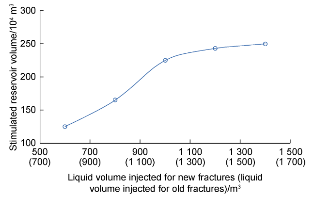
Fig. 13 Relationship between simulated fracturing fluid volume and stimulated reservoir volume. |
4.3. Combination of displacement and imbibition under complex fracture network
The fracturing fluid imbibition and displacement will occur in well soaking process after fracturing, which improve the oil-water distribution. In the process of well soaking, the continuous flow of fluid can increase the pressure diffusion surface and improve the energy distribution. Through the energy replenishment before fracturing and injection of fracturing fluid during fracturing, the reservoir pressure rises obviously. In the process of well soaking after fracturing, the pressure spreads from old fractures to new fractures and other undeveloped areas, which increases the control range of single well and the overall pressure of reservoir and effectively supplies the reservoir energy. The reasonable well soaking time can give full play to the imbibition and displacement of fracturing fluid. It improves the displacement effectiveness and reduces the water cut of produced liquid. The numerical simulation of well soaking time optimization (Fig. 14 ) shows that when well soaking time is less than 40 d, the imbibition capacity increases significantly with time. Moreover, when well soaking time is more than 60 d, the imbibition capacity remains basically unchanged. Hence the reasonable well soaking time in the test area is determined to be 40-60 d.
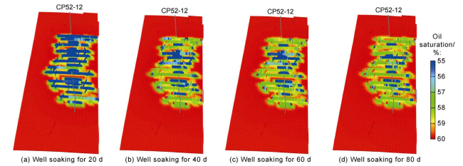
Fig. 14 Distribution of oil saturation in reservoirs under different well soaking times after the repeated fracturing. |
In order to compare the development effects of three methods: the continuous water flooding between injection-production wells in tight oil reservoir (water flooding for short), the single-well water flooding and imbibition (huff and puff imbibition for short), and the combination of displacement and imbibition with huff and puff in a well and oil producing from adjacent wells (combined displacement and imbibition for short), an on-line nuclear magnetic resonance measurement experiment was carried out, which combined the oil saturation imaging with evaluation of pore throat producing at different scales. The experimental results are shown in Fig. 15. The traditional modes of water flooding, huff and puff imbibition fail to cause the efficient imbibition and replacement between injected water and the matrix, but drive the crude oil near the fractures far away from the fracture zone. However, “huff and puff in a well + producing oil from adjacent wells” can give full play to the role of displacement and imbibition, and strengthen the displacement between wells and imbibition around fractures. Compared with the traditional displacement modes, the oil displacement efficiency of the combination of displacement and imbibition can be improved by 8.6 percentage points.
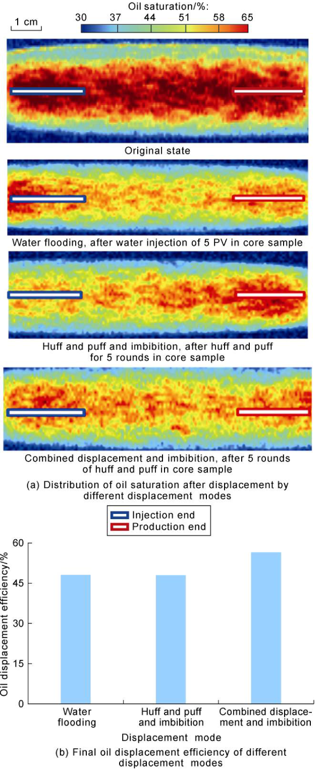
Fig. 15 Experimental results of different displacement modes. |
By adopting the technology of combination of displacement and imbibition, the contact area between water and matrix is large enough and with sufficient imbibition time under the condition that the fracture network is fully reconstructed. Breaking the restriction of well pattern and well type, the asynchronous injection-production without distinction in well type can play the dual roles of imbibition and displacement. Give full play to the spontaneous imbibition and displacement of tight oil reservoir at a reasonable water drive speed, and further improve the oil displacement efficiency by adjusting the capillary pressure of spontaneous imbibition and reasonable displacement pressure difference of tight oil reservoir. Specifically, the well group is regarded as the basic injection-production unit, and the injection-production mechanism of alterative water injection between wells is adopted. The locations of water injection wells are exchanged in different injection-production cycles to complete the life cycle. Similar to the single well huff and puff technology, each injection-production cycle of the combination of displacement and imbibition is still divided into three stages: injecting water and increasing pressure, shutting in well for imbibition, and opening well for oil production. In the stage of water injection, the water is injected through huff and puff wells and flows to offset wells along the artificial fracture network, and enters the natural fractures and matrix macropores to replenish formation energy and displace crude oil to the offset wells. In the stage of well shut-in for imbibition, the injected water diffuses into more natural (micro) fractures and matrix macropores, and enters matrix micropores and replaces crude oil under the action of imbibition at the same time. In the stage of well opening for oil production, the reservoir liquid is produced simultaneously from water injection wells and adjacent wells driven by formation energy.
The combination of displacement and imbibition is based on the new well pattern design, which diversifies the displacement methods and makes full use of the fracture network system and imbibition mechanism. Comprehensive utilization of horizontal well inter-fracture displacement technology [7] and combination of displacement and imbibition can improve the remaining oil producing rate of reservoir and further improve the efficiency of displacement system. Fully considering the effect of fracturing technology, we should select appropriate measure according to the specific well and make comprehensive strategy when making development plan. For the well group with large staged spacing, the scheme of injection-production between fractures is adopted. For the well group after repeated fracturing, the comprehensive energy supplement scheme combining inter-well displacement with imbibition is adopted.
5. Field application
The Yuan 284 Block in Huaqing Oilfield is characterized by large geological reserves, thick oil layers and poor physical properties. The small-scale fracturing combined with conventional water drive mode was mainly used for development earlier. However, the poor connectivity of sand bodies and micro-scale seepage make it difficult to establish an effective displacement pressure system by water injection. Therefore, the proportion of low-production wells is large, the multi-directional fractured flooding is serious and the oil production rate is low, with the recovery degree is only 2% in 10 years. The conventional injection-production adjustment and profile control and flooding are ineffective, which makes it difficult to effectively improve the development effect. Since 2018, new energy-increasing fracturing technology and the development mode of flexible injection-production and displacement- imbibition combination for tight oil reservoir in this paper have been applied in this block. The Class III reserves of tight oil reservoir with poor physical properties have been effectively produced. After the reconstruction of stress, seepage and pressure fields in three typical wells in the test area, the daily oil production increased from an average of 2.9 t to 10.5 t and remained stable (Fig. 16 ). The fracture-controlled reserves increased by 262%, and the formation pressure increased by 45% and the oil recovery increased by 8 percentage points.
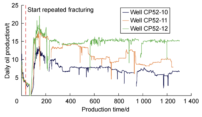
Fig. 16 Production performance of typical wells in Yuan 284 Block before and after repeated fracturing. |
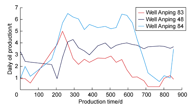
The development test of multi-well linkage displacement combined with imbibition was carried out in the study area, which prevented the injected water channeling along the fracture, and promoted the injected water to enter the pore throat deep in the matrix system. It expanded the swept volume, and improved the development effect. The daily oil production of typical wells increased by 2-5 t, the oil production rate increased from 0.19% to 1.15%, and the oil recovery factor further increased by more than 4 percentage points (Fig. 17 ). At the same time, the new development mode has greatly reduced the ineffective water injection, and the injection-production ratio has been reduced from 3.8 to 1.2, which saved water resources, improved economic benefits, and achieved energy saving, cost reduction and efficiency improvement in the development of tight oil reservoir.
Fig. 17 Daily oil production of typical well groups under the mode of combined displacement and imbibition. |
6. Conclusions
After the long-term water injection development in tight oil reservoir, the formation energy has the following three characteristics: (1) The pressure diffusion range is small and the energy transfer efficiency is low; (2) The variation range of in-situ stress is different. The variation range of horizontal minimum principal stress is greater than that of horizontal maximum principal stress, and the variation range of water injection well is greater than that of production well; (3) The in-situ stress has a steering effect, and the steering angle of in-situ stress around the water injection well is larger.
The development model of multi-field reconstruction and combined displacement-imbibition can improve tight oil recovery: Through the conversion of water injection wells to production and large-scale fracturing technology, the flexible well pattern without distinction in well type is constructed and the seepage mode is changed. By optimizing the geological energy field through energy replenishment before fracturing and the amount of injected fluid during the fracturing process, the largest scale of fracture system can be built. Further expand the diffusion range of geological energy field through the well soaking after fracturing to make full use of imbibition and displacement of oil and water. For well groups with large staged spacing, it is advisable to adopt an inter-fracture injection-production scheme. Moreover, for well groups after repeated fracturing, the comprehensive energy supplement scheme combining multi-well linkage with inter-well displacement and imbibition should be adopted.
Through field practice, it is proved that the technology of multi-field reconstruction and combined displacement-imbibition can greatly improve the tight oil recovery and provide technical support for efficient development in tight oil reservoir.
Nomenclature
An—characteristic area, m2;
b—Biot coefficient;
C—flexibility model matrix;
Cdr—the fourth-order tensor of elastic drainage volume modulus, Pa;
CL—Carter filtration coefficient, m/s1/2;
d— distance between the centers of adjacent grids, m;
df—center distance between adjacent fracture units, m;
dn—characteristic distance, m;
Dn, Ds—normal and tangential displacement, m;
fL,i, fV,i—fugacity of component i in liquid and gas phase, Pa;
fx, fy—the first derivative of constant Green's function to x and y, m;
fxx, fxy, fyy—the second-order partial derivatives of xx, xy, yy of constant Green's function, dimensionless;
fxyy—the first derivative of constant Green's function to x and the second derivative of y, m−1;
fyyy—the third derivative of constant Green's function to y, m−1;
g—acceleration of gravity, m/s2;
g—gravity acceleration vector, m/s2;
gx, gy—the first derivative of linear Green's function to x and y, m;
gxy, gyy—the second-order partial derivative of linear Green's function to xy and yy, dimensionless;
gxyy—the first derivative of linear Green's function to x and the second derivative of y, m−1;
gyyy—the third derivative of linear Green's function to y, m−1;
G— shear modulus of elastic medium, Pa;
H—height, m;
hL—height of filtration area, m;
Hfl—height of fluid in fracture, m;
i—carbon component number;
K—absolute permeability, m2;
Kf—fracture permeability, m2;
Kn, Ks—normal and tangential stiffness, N/m;
Krw, Krg, Kro—relative permeability of water, gas and oil, %;
Lint—length of fracture intersection line, m;
nc —number of carbon components;
pE—equivalent fluid pressure, Pa;
pw, pg, po—pressure of water, gas and oil phases, Pa;
q—fluid velocity in fracture, m/s;
qi—mass flow of carbon component i in unit volume, kg/(m3·s);
qL—filtrate loss, m/s;
qw— mass flow of water phase in unit volume, kg/(m3·s);
Q— fluid flow rate, m3/s;
s—fluid flow distance, m;
Sw, Sg, So—saturation of water, gas and oil, %;
t—time, s;
t0—the first time of fracture unit contacted with fracturing fluid, s;
T—conductivity, m3;
Tf—conductivity of single fracture sheet, m3;
ux(x, 0-)—moving distance in negative direction along the fracture strike, m;
ux(x, 0+)—moving distance in the positive direction along fracture strike, m;
uy(x, 0-)—moving distance along the negative direction perpendicular fracture, m;
uy(x, 0+)—moving distance along the positive direction perpendicular fracture, m;
u—displacement vector, m;
V—volume, m3;
Vc—unit-controlled volume, m3;
$\bar{w}$—average width, m;
wf—fracture width, m;
x, y—rectangular coordinate system, m;
xi, yi—mole fraction of carbon component i in oil-gas two phases, %;
δ—second-order Kroneck operator;
ε—strain tensor, dimensionless;
εv—volume strain, which is defined as the trace of strain tensor ε in the flow equation;
μw, μg, μo—viscosity of water, gas and oil phases, Pa·s;
ρf—total density of fluid, kg/m3;
ρs—rock density, kg/m3;
ρw, ρo, ρg—density of water, gas and oil phases, kg/m3;
σxx, σyy—components of normal stress in xx direction and yy direction, Pa;
τxy—component of shear stress in xy direction, Pa;
υ—Poisson's ratio;
ϕ— true porosity, %.