

Introduction
Complex thick carbonate reservoirs are well-developed and widely distributed in the Cretaceous strata in the Middle East [1]. Such reservoirs have high geological reserves and remaining recoverable reserves, but the degree of recovery from these reservoirs is less than 8%. Under the dual control of sedimentation and diagenesis, they are complex and vary greatly in lithology, physical properties and microstructure. Reservoirs with different genesis are superimposed, resulting in high heterogeneity in the lateral and vertical directions, which makes the development difficult.
In the early stages of development, due to the limited availability of data, the heterogeneity of thick carbonate reservoirs was not adequately understood, and it was believed that such reservoirs developed continuously throughout oil fields. For this reason, the main development mode adopted in such reservoirs is commingled injection and production [2]. As waterflooding was carried out, problems such as early water breakthrough in production wells, rapid increase in water cut, great decline in single-well production, slow recovery of reservoir pressure, and highly unbalanced development of reserves have gradually exposed during commingled injection and production based on a well pattern, and only a very limited number of intervals has contributed to oil production [2]. To solve these problems, it is imperative to adjust development strategies and adopt new ideas in field development. The carbonate reservoirs in China are mainly fractured-vuggy, fractured-porous, and porous-vuggy. Through long-term practices in the development of such reservoirs, waterflooding techniques centered on spatially structured well patterns, variable-intensity water injection, plugging and channeling prevention have been developed [3]. The thick carbonate reservoirs in the Middle East are porous reservoirs, consisting of a larger number of oil-bearing layers in the vertical direction and well-developed baffles and barriers. The waterflooding behavior of these reservoirs is mainly affected by vertical heterogeneity and gravity [4]. Research and practice over the years show that separate-layer waterflooding is an effective strategy to improve development performance in thick carbonate reservoirs and is also suitable for other types of carbonate reservoirs [5]. However, there is still a lack of systematic research on the concept, implementation principles, and key technologies of separate-layer waterflooding.
Based on the waterflooding practices in the carbonate reservoirs of the Middle East and taking the thick Cretaceous bioclastic limestone reservoir in the Iran-Iraq region as an example, a balanced waterflooding development technique for complex thick carbonate reservoirs is proposed to improve poor development effect caused by commingled injection and production. The core idea of this technique is fine division of development units by concealed baffles and barriers, combination of multiple well patterns and multiple well types, and the construction of balanced water injection and recovery system. The purpose is to produce different types of reserves in a balanced manner, control water breakthrough and water cut in production wells to the maximum extent, and ensure continuous, stable production and efficient development of thick carbonate reservoirs.
1. Thick carbonate reservoirs
1.1. Geological characteristics
The Cretaceous strata in the Iran-Iraq region is situated on a passive continental margin and deposited in a gentle shallow carbonate ramp, relatively stable structures, a warm and humid climate, strong hydrodynamic forces, thriving rock-forming biology, and develop thick bioclastic limestone reservoirs [6]. The lithologies in the vertical direction are complex and vary significantly. The rocks have low textural maturity and rich bioclasts. The bioclasts differ in terms of physical structure and chemical composition, resulting in differences in their resistance to compaction and dissolution [7]. Multi-stage sedimentary cycles in thick carbonate reservoirs indicating frequent changes and evolution in depositional environment, with the bioclasts altered by differential diagenesis, the reservoirs differ greatly in physical properties due to the combined effects of complex depositional and diagenetic processes[8-9]. The overlapping zones between the petrophysical properties of different sedimentary facies are large, and the ranges of the petrophysical properties of the same sedimentary facies are wide, resulting in high vertical heterogeneity of thick carbonate reservoirs [10-11]. Taking the Cretaceous Mishrif Formation in Oilfield A in the Middle East as an example, there are large overlapping zones between the petrophysical properties of the MB2-1 reef-shoal facies and the overlying MB1-2C lagoon facies. Specifically, for the reef-shoal facies reservoir, the porosity range is nearly 20%, and permeability max-min ratio (permeability ratio for short) is nearly 40; for the lagoon facies reservoir, the porosity range is up to 25%, and permeability ratio reaches 1 000 (Fig. 1 ).
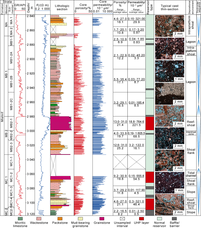
Fig. 1. Characteristics of the thick carbonate reservoir in Oilfield A in the Middle East. GR—gamma ray; Rt—formation resistivity. |
Ultra-high-permeability (UHP) zones and concealed baffles and barriers are generally developed in thick carbonate reservoirs. The total thickness of UHP zones is usually less than 10% of reservoir thickness; the permeability of UHP zones is usually higher than 100×10−3 μm2 and may even reach the level at square micron, and it is usually higher than the permeability of the surrounding rock by 2 to 4 orders of magnitude [12-13]. For example, the permeability of the UHP zones distributed in the MB2-1, MC1-2 and MC1-4 intervals of the Mishrif Formation in Oilfield A is nearly 2 orders of magnitude higher than that of the surrounding rock (Fig. 1 ). Oil and gas are mainly produced from UHP zones during natural depletion, but the injected water advances rapidly along UHP zones during waterflooding, and the hydrocarbons in reservoirs with relatively low permeability cannot be effectively displaced. Consequently, premature water breakthrough or water channeling can occur in production wells, resulting in ineffective water circulation. The “concealment” of baffles and barriers is reflected in the six aspects described below. (1) Development environments: Baffles and barriers can develop in low-energy lagoons, deep-water shelf and high-energy reef-shoal, where the control degree by facies is low [14-15]. (2) Textures and components: With low shale content and high particle content, baffles and barriers contain not only mudstone or micrite, but also packstone and sparry grainstone. (3) Petrophysical properties: Despite with the low permeability, baffles and barriers have relatively high porosity, and the related core samples exhibit good oil-bearing properties and high visual porosity. (4) Scale: Baffles and barriers vary in thickness from only 10 cm to 20 m (the total thickness of multiple superimposed baffles or barriers), and the range of a single baffle or barrier is limited, but the distribution range of a set of superimposed baffles or barriers is relatively large. (5) Development characteristics: During oil/gas production, fluid migration can still occur along geologically determined baffles and barriers, while other geologically determined non- baffles and barriers have sealing/shielding ability. (6) Geophysical characteristics: Due to the unique properties such as shale content, porosity and oil-bearing properties, the well logs of baffles and barriers are characterized by low to medium gamma ray (GR), medium to high resistivity, and low to medium density. In the Mishrif Formation, there are few mudstone baffles/barriers that can be clearly identified based on well logs. Because the baffles and barriers in the 400 m thick Mishrif Formation are “concealed”, the host country of resources and some western oil companies have developed the Mishrif reservoir as one system by commingled injection and production in the past few decades.
1.2. Production
In the early stage of oilfield development, the commingled injection and production by depletion drive is generally employed, and overall perforation is carried out without separating layers in the vertical direction. Although this technique can ensure high oil production and quickly achieve large-scale production, oil is mainly produced from UHP zones whose total thickness accounts for a relatively small proportion, resulting in short period of stable high production and rapidly decline in formation pressure; in comparison, the reserves in low-permeability layers whose total thickness accounts for a relatively large proportion have not been recovered yet, and it is urgently required to replenish reservoir energy through water injection. After full-scale waterflooding was initiated, the original well pattern was still used for commingled injection and production. The thick reservoir was dominated by low-viscosity oil and highly heterogeneous, with well-developed UHP zones. For these reasons, the injected water flowed rapidly along zones with ultra-high or relatively high permeability, resulting in premature water breakthrough, rapid increase in water cut, or severe water channeling in production wells, while the oil in surrounding reservoir with relatively low permeability had not been effectively displaced. After water injection was carried out, the formation pressure recovered to a certain extent, but the decline in oil production still remained, and water injection and oil production were highly unbalanced. Under normal circumstances, commingled injection and production can only recover about 1/3 of the geological reserves, which is difficult to achieve balanced recovery of reserves.
The high heterogeneity of the thick carbonate reservoirs in the Middle East and the inadequate understandings thereof have posed severe challenges to the scientific development. Therefore, it is imperative to adopt new development ideas and explore efficient waterflooding strategies suitable for these reservoirs. By summarizing the practice and experience in the development of these reservoirs by waterflooding, the concept and technique of “separate-layer balanced waterflooding” were proposed, through which the balanced development of different types of oil/gas reserves was achieved.
2. Theory and principle of balanced waterflooding development
2.1. Theory of balanced waterflooding development
Balanced separate-layer waterflooding is a technique designed to reduce the impact of the heteogeneity of complex thick reservoirs and achieve desired development results by changing the mode from “one strategy for one reservoir” to “one strategy for one development unit”, dividing thick reservoir into mutiple relatively homogeneous development units with different properties, and implementing a well-targeted production strategy for each. (1) Basis for application: Different intervals in thick and highly heterogeneous reservoir are considered have certain geological reserves and differ significantly in terms of petrophysical properties and connectivity. The carbonate reservoirs in the Middle East are thick, inte-grated, and highly heteogeneous in the lateral and ver-tical directions, with the basis for fine division of development units. (2) Necessary conditions: The pre-sence of effective physical barriers is a necessary condition for balanced separate-layer waterflooding. Stable barriers, poor reservoir, and non-permeable layers resulting from permeability ratio can all serve as effective physical barriers. (3) Key techniques: The key techniques for balanced separate- layer waterflooding include the stratigraphic division of thick reservoir, baffle/barrier identification and characterization, sealing capacity evaluation and well pattern optimization. (4) Objective: The objective of balanced separate-layer waterflooding is to recover geological reserves from thick, highly heterogenous reservoirs to the maximum extent. After separate-layer waterflooding, the water cut is effectively controled, the reservoir pressure is remained constant or declines at a reasonable rate, and the sweep efficiency is effectively improved, thus enhancing oil recovery from such reservoirs.
2.2. Principles of division of development units
The division of development units should be performed taking into account of the geological characteristics of reservoirs based on the principles listed below: (1) The reservoirs in each development unit must be relatively homogeneous, and the structural characteristics, oil-bearing area, properties of oil-bearing layers, oil-water contact, and petrophysical properties within the same development unit must be basically the same. (2) Each development unit must contain oil-gas reserves of a certain scale, and have a certain pay zone thickness, oil well production capacity and single-well controlled reserves to ensure that certain production capacity and long-term stable production can be achieved after separate-layer waterflooding is implemented. (3) Microstructure is an important factor controlling the efficiency of oil displacement by water injection. Considering the complex microstructure of thick carbonate reservoirs in the Middle East and the differences in fluid flow through pore throats in different modes, the microstructure within the same development unit should be as similar as possible. In other words, only one mode is existed such as unimodal, bimodal or multimodal microstructure so as to ensure the balanced waterflooding. (4) Adjacent strata should be divided into development units when there are stable baffles/barriers that can provide effective shielding against formation fluids. When no continuous and stable barriers is developed in the strata, the continuously distributed poor reservoir that can effectively separate the overlying and underlying strata can be considered as barriers. (5) When the reservoirs in two adjacent formations are greatly different or the permeability ratio of two formations is more than 10, the pressure transfer and fluid exchange occur between the two formations but have no significant impact on oil/gas production, the two formations can be treated as separate development units even if they contain no stable baffles/barriers or poor reservoir. (6) If the types of wells or well patterns required by two adjacent formations are greatly different, the two formations should be considered two separate development units. (7) Any development unit that is highly heterogeneous or where reservoir thickness is relatively large may be further divided for separate-layer waterflooding. (8) If a reservoir exhibits varying characteristics in different areas in plane, different techniques and strategies of balanced waterflooding would be implemented for different areas accordingly.
3. Key techniques for balanced waterflooding development
3.1. Concealed baffle and barrier identification and characterization
For cored wells, based on the characteristics of concealed baffles and barriers, the key factors controlling fluid flow were analyzed to identify the theoretical baffles and barriers. (1) In thick carbonate reservoirs, stable baffles and barriers mainly develop at maximum flooding surface or the top boundaries of third-order sequences. Deep-water deposits occur at maximum flooding surface, where shale content is high and with stable distribution. At the top boundaries of third-order sequences, physical barriers can be formed, or flow barriers may be formed due to permeability contrast between the upper and lower strata. (2) Strong cementation is a key factor controlling the development of baffles and barriers. Physical barriers can be formed after strong cementation in both high-energy and low-energy depositional environments. (3) Since the deposits in low-energy settings are characterized by high shale content and weak cementation, the flow capacity needs to be assessed based on their microstructure. The statistical analysis of nearly 2 000 core samples from thick carbonate reservoirs in Iran-Iraq region shows that deposits in low-energy settings are dominated by micropores. Normally, when the maximum pore-throat size is less than 0.5 μm, the permeability of these deposits is still less than 1.0×10⁻³ μm2 even if their porosity is high. To sum up, boundaries of third-order sequences, strongly cemented facies, and microporous unimodal deposits in low-energy settings can be used as geological constraints for the identification of baffles and barriers. Any layer meeting one or more of these conditions can be identified as a theoretical baffle/barrier. Five types of baffles and barriers in thick carbonate reservoirs of Iran-Iraq region have been identified, that is, weathered and peat baffles and barriers occur at the boundaries of third-order sequences, baffles and barriers of lagoon facies and bioclastic shoal facies controlled by strong cementation, and deep-water sedimentary baffles/barriers developed in microporous unimodal deposits in low-energy settings.
Theoretical baffles and barriers do not necessarily have a sealing ability. Real baffles and barriers can be identified by removing the theoretical baffles and barriers without sealing ability based on dynamic data. Each real baffle/barrier needs to meet at least one of the following conditions: (1) there are pressure gradient anomalies above and below the baffle/barrier; (2) there is no production from the baffle/barrier during well testing with PLT (production logging tools), but the surrounding rock formation is productive; (3) the pressure gradients in the overlying and underlying strata are normal, but the permeability ratio between the overlying and underlying strata is greater than 10. It has been verified that the aforementioned five types of layers are all real baffles and barriers.
Through the fine calibration of lithological-electrical logs, the identification criteria of well logs for real baffles/barriers were established. Under normal conditions, the well-log curves for baffles/barriers controlled by sequence boundaries change greatly in amplitudes and are highly serrated. Therefore, such baffles/barriers can be identified based on the shape of their well-log curves. However, due to large values overlaps of related well logs, it is difficult to effectively identify other types of baffles/barriers from reservoirs through well log, resulting in higher interpretation error rate. Such difficulty in the identification of concealed baffles and barriers can be overcome using “interval-controlled” and “facies-controlled” approaches to reduce errors in well log interpretation. The “interval-controlled” approach is based on the accurate understanding and identification of the depositional patterns of various intervals. In this approach, certain baffles and barriers are confined to a particular interval where the baffles/barriers can be identified to a certain extent based on the well logs from this interval. This approach can distinguish between deep-water and lagoon-type baffles/barriers whose well logs are highly similar. But these baffles/barriers do not coexist in the same interval due to their formation at different water depths, and can be identified in a particular interval based on the pattern of depositional evolution. The “facies-controlled” approach is mainly used to identify cementation-controlled baffles/barriers hidden in high-energy deposits because the well logs of such baffles/barriers are significantly different from those of high-energy deposits. If such baffles/barriers are confined to high-energy deposits, the reservoirs in other sedimentary facies will not be incorrectly identified as baffles/barriers. It is uncertain whether the five types of theoretical baffles/barriers determined through well log interpretation have the sealing ability or not. Similarly, real baffles and barriers can be determined through verification based on dynamic data. The identification of real baffles and barriers can be performed through fine well-seismic calibration.
3.2. Sealing ability evaluation of concealed baffles and barriers
The lateral continuity and vertical sealing ability of baffles and barriers are key factors that determine whether or not a reservoir can be developed by separate-layer waterflooding. The lateral continuity of baffles and barriers can be semi-quantitatively or quantitatively evaluated using methods such as geological models, well log correlation and seismic data-based prediction. Deep-water and weathered baffles/barriers have high lateral continuity and a strong vertical sealing ability. The sealing ability of such baffles/barriers is usually evaluated based on their thickness. Taking the Mishrif Formation in southern Iraq as an example, Deep-water and weathered baffles and barriers more than 2 m thick have a very strong sealing ability, those with thicknesses ranging from 1 m to 2 m have a certain sealing ability, and those less than 1 m thick have a poor sealing ability. Peat baffles and barriers have a strong vertical sealing ability, which is greatly affected by their lateral continuity. The key to evaluating their sealing ability is to restore the environment of peat deposition and predict their scale. Normally, peat baffles and barriers with a lateral range greater than 2 000 m can provide complete sealing within the area covered by the injection-production well group, those with a lateral range of 1 000-2 000 m can provide partial sealing, and those with a lateral range smaller than 1 000 m are incapable of sealing. Lagoon-type and bioclastic shoal-type baffles/barriers mainly achieve sealing effects relying on the vertical superposition of tight layers. However, the laterally contiguous range and vertical thickness of tight layers are highly random, the petrophysical properties vary with the degree of cementation, and the permeability of these layers determines the total vertical permeability under the fixed total thickness of superimposed tight layers. The simulation analysis performed with mechanism models of baffles/barriers shows that, when the total thickness of the tight layers is greater than 10 m and the permeability is less than 0.05×10⁻³ μm2, the total vertical permeability does not exceed 0.30×10⁻³ μm2 even if the matrix permeability reaches 10.00×10⁻³ μm2 (Fig. 2 ), indicating that these tight layers have a certain sealing ability. Therefore, lagoon-type and bioclastic shoal-type baffles/barriers can provide vertical sealing when they are more than 10 m thick and with the permeability of their cemented portions less than 0.05× 10⁻³ μm2. In summary, the key parameters for evaluating the sealing ability of various types of baffles/barriers are thickness for deep-water and weathered baffles/barriers, lateral continuity and range for peat baffles/barriers, and total thickness and the permeability of tight layers for lagoon-type and bioclastic shoal-type baffles/barriers.
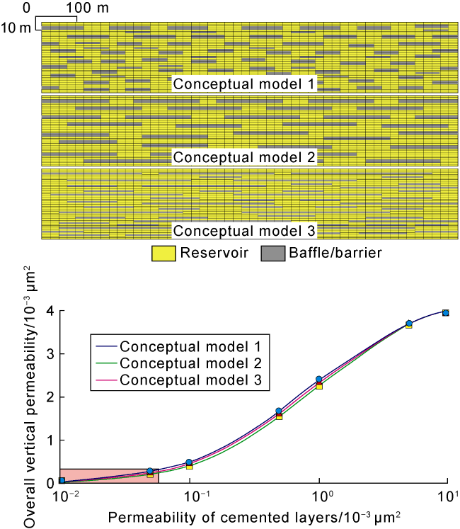
Fig. 2. Simulation of the vertical permeability of cementation-controlled baffles/barriers. |
3.3. Balanced waterflooding development
3.3.1. Principles for implementation
For similar reservoirs being developed by waterflooding, their basic well patterns and production scales have generally been formed through early development activities. The principles for the arrangement and adjustment of well patterns and layers are as follows: (1) Build a three-dimensional injection-production system where the strata are divided into multiple layers in the vertical direction and multiple zones in the horizontal direction with water injected at separate stages, adhere to the principle of water injection at moderate intensity and strict control of differential pressure and injection-production ratio (IPR) during production; (2) Redefine the reservoir type and drive mechanism for each development unit, optimize the injection-production well pattern of each development unit to ensure effective replenishment of reservoir energy; (3) Optimize the matching relation of the reservoirs at various levels and development mode, reduce interlayer interference, achieve balanced production of reserves from reservoirs at various levels, maximize oil recovery during production periods with zero or low water cut; (4) Select transition layers or alternative reservoirs to compensate for the production loss during adjustment periods, achieve the smooth transition and conversion between the old and new well patterns, and ensure the achievement of contractually specified production goals and benefits maximization.
3.3.2. Balanced waterflooding modes
While the thick carbonate reservoirs in the Iran-Iraq region share regionally comparable commonalities, they differ in structure and heterogeneity due to lateral sediment migration and differential diagenesis. Based on exploration, research and practice for more than ten years, the concept of “balanced separate-layer waterflooding” for complex thick carbonate reservoirs was proposed, and the three balanced waterflooding modes and techniques based on the conventional, fine and deepened stratigraphic frameworks were summarized to provide reference for the optimization of field development for similar reservoirs.
(1) Conventional stratigraphic framework. In this framework, there are regionally stable and easily identifiable baffles/barriers that can provide effective sealing and be used to divide the formation into separate development units. The well type and well pattern suitable for each development unit can be formed by optimizing well-type configuration and well-pattern deployment and reasonably designing the well spacing (between injection and production wells) and infill drilling frequency. Inject the water at moderate intensity to achieve larger sweep area and optimal waterflooding efficiency and improve the degree of comprehensive recovery from reservoirs at different levels. As shown in Fig. 3 , Cap B (a barrier) of the Mishrif Formation reservoir in Oilfield R is uniformly distributed across the entire field, dividing the reservoir into two intervals, namely, MA1-MA2 and MB1-MB3. The high-quality reservoirs in MA1-MA2 are relatively thin and have poor petrophysical properties. In the early stage of oilfield development, a five-spot well pattern of horizontal wells can be used for waterflooding in MA1-MA2, where the quantity ratio of injection wells to production wells is 1:1, and the water injection intensity should be appropriate to ensure that the wells producing from low-permeability reservoirs can be quickly affected by the injected water in multiple directions and produce oil at high rates. In the middle and late stages of oilfield development, local infill drilling may be considered based on the distribution of remaining oil, and the five-spot well pattern can still be used for waterflooding. The southern and northern sections of the MB1-MB3 interval differ significantly in terms of thickness and petrophysical properties. Specifically, the reservoirs in the north are relatively thick and have good petrophysical properties, while those in the south are relatively thin and have poor petrophysical properties. With the advantages of good petrophysical properties and sufficient reservoir energy, an inverted nine-spot well pattern of vertical wells can be used for waterflooding from this interval in the early stage of oilfield development. In the middle and late stages of oilfield development, adjustments would be made as appropriate. For the southern section of MB1-MB3, the inverted nine-spot well pattern will be continued to use in the middle stage, and local infill drilling will be considered based on the distribution of remaining oil in the late stage. For the northern section of MB1-MB3, a five-spot well pattern will be used in the middle stage to adjust the flow field, increase the number of injection wells and maintain an appropriate IPR, thus achieving the balanced displacement. In the late stage, local infill drilling will be carried out once or twice depending on the abundance of reserves and petrophysical properties in plane.
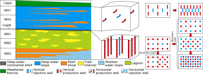
Fig. 3. Balanced separate-layer injection and production model for the Mishrif Formation in Oilfield R in the Middle East. |
(2) Fine stratigraphic framework. In this framework, stable and concealed baffles/barriers coexist in the reservoir, and the concealed baffles and barriers can provide effective sealing and be used to further subdivide the formation into development units. Based on the fine characterization of concealed baffles and barriers, the reservoirs at low levels are subdivided, and the specific well type and well pattern suitable for each development unit are determined based on the properties of reservoirs of each unit, realizing adjustment in stages of well patterns of various layers to reduce interlayer interference and improve the recovery degree in the vertical direction. As shown in Fig. 4 , the MB1-1 submember of the Mishrif Formation in A Oilfield is a stable barrier distributed across the entire field. A set of concealed baffle/barrier controlled by cementation was developed at the bottom of MB1 and a set of concealed peat baffle/barrier was developed at of the top of MB2-2 submember. Based on the distribution of baffles/barriers, an independent well pattern can be deployed for MA2 first, with an injection-production pattern consisting of several rows and columns of horizontal wells. Based on the distribution of internal baffles/barriers, the MB1-2 submember can be further subdivided into MB1-2A-MB1-2B and MB1-2C. For each of the two submembers, a five-spot well pattern is deployed, which will be converted into a row-column pattern in the late stage, and conducting fine-scale separate-layer water injection based on reservoir thickness and intralayer heterogeneity. Based on the distribution of internal baffles/barriers, the MB2-MC1 section can be further divided into MB2-1 and MB2-2-MC1. A well pattern consisting of vertical injection wells at edges and horizontal production wells at structural highs can be applied in MB2-1, and a well pattern consisting of vertical wells for water injection from the bottom and horizontal wells for oil production from the top can be applied in MB2-2-MC1.
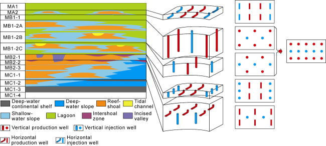
Fig. 4. Balanced separate-layer injection and production model for the Mishrif Formation in Oilfield A in the Middle East. |
(3) Deepened stratigraphic framework. If the reservoir contains both stable and unstable baffles/barriers or two adjacent intervals differ greatly in terms of petrophysical properties and reservoir type or reservoir structure, a “deepened stratigraphic framework” can be established to conduct separate-layer waterflooding based on the actual reservoir conditions relying on interlayer heterogeneity or unstable baffles/barriers. As shown in Fig. 5 , risks such as water channeling through adjacent high-permeability zones of the Mishrif Formation in B Oilfield may occur. Therefore, it is necessary to deepen the spatiotemporal framework of the formation, take the entire oil-bearing layer in the middle section as a regional barrier, prioritize the deployment of injection and production wells for the overlying and underlying layers, and reasonably optimize well types and well spacing based on the petrophysical properties of reservoirs. In the late stage of oilfield development, production from the middle layers involving the risk of water channeling through high-permeability zones should be commenced at the appropriate time to achieve balanced oil recovery from reservoirs with different petrophysical properties. CRII is a stable barrier between MA and MB1 that is distributed across the entire field. There is no well-developed barrier between MB1 and MB2, but the petrophysical properties of MB1 are greatly different from those of MB2. Based on interlayer heterogeneity and the distribution of barriers, the reservoir can be divided into the following four development units from top to bottom: MA, MB1, MB2-1, and MB2-2-MC. Considering the risk of water channeling between the tidal channels in MB1 and the UHP zones of the underlying MB2-1 submember, the entire MB1 interval will be treated as a “barrier” and excluded from production. Priority should be placed on the deployment of horizontal injection and production wells for oil production from MB2 and MC, which have large geological reserves; meanwhile, an injection-production well pattern consisting of vertical wells can be used for oil production from MA. In the late stage, a flexible five-spot injection-production well pattern (vertical wells) will be used to produce from MB1 at the appropriate time. MB2-1 submember at the upper of MB2 is an UHP zones, and MB2-2-MC is an interval with low-permeability and ultra-low-permeability reservoirs at the lower section without baffle/barrier in MB2. However, considering that MB2 and MC differ sufficiently from each other in terms of petrophysical properties, they can be divided into two development units, namely, MB2-1 and MB2-2-MC. The water is injected from the edge via horizontal injection wells in MB2-1 submember, and in the middle and late stages of oilfield development, the horizontal production wells at edges will be converted to horizontal injection wells when water breakthrough or channeling occurs in these production wells. A well pattern consisting of upper horizontal injection wells and lower horizontal production wells will be employed in MB2-2-MC3 to achieve gravity displacement. In the middle and late stages of oilfield development, infill drilling will be considered based on the distribution of remaining oil. The deepening of the stratigraphic framework can effectively mitigate water channeling through high-permeability zones and achieve balanced oil recovery from low-permeability reservoirs that are hard to produce.
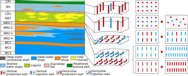
Fig. 5. Balanced separate-layer injection and production model for the Mishrif Formation in Oilfield B in the Middle East. |
4. Application effects of balanced waterflooding development
Using the techniques and methods described above, the baffles and barriers in the thick and heterogeneous reservoir of the Mishrif Formation in Oilfield R, Oilfield A, and Oilfield B in the Middle East were identified, characterized and evaluated. The Mishrif Formation was divided into multiple development units, which were developed with targeted modes and varying three-dimensional well patterns to improve the well-control and recovery degree. In order to verify the effectiveness of the proposed development strategy, the effect of commingled injection and production was comparatively analyzed with that of separate-layer waterflooding in three oilfields by numerical simulation. The development periods set for these oilfields are 70 years for Oilfield R, 12 years for Oilfield A, and 25 years for Oilfield B. For numerical simulations, the total number of wells for separate-layer waterflooding is the same as the total number of wells for commingled waterflooding. In other words, during the simulation process, no additional wells were used for separate-layer waterflooding, but instead suitable well patterns and well types were used for different development units.
The Mishrif Formation in Oilfield R is nearly 200 m thick and contains three barriers located at the top of the Mishrif Formation, the top of MB1, and the bottom of MB2. The barrier at the top of MB1 is only 1-3 m thick and uniformly distributed across the entire field. The barrier at the bottom of MB2 is thick, but it is not distributed across the entire field and thus cannot be used as the basis for development units division (Fig. 6 ). Therefore, the Mishrif Formation in Oilfield R was divided into two development units based on the barrier at the top of MB1. Considering the geological characteristics of Oilfield R, the development mode based on the conventional stratigraphic framework was adopted.
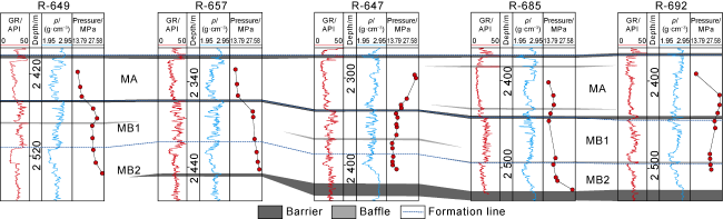
Fig. 6. Distribution of barriers and baffles in the Mishrif Formation of Oilfield R in the Middle East. ρ—formation density. |
The numerical simulation results show that, compared with commingled injection, separate-layer water has achieved significantly better development effect and effective control of water cut. For commingled injection in Oilfield R, the degree of recovery from the lower part of the reservoir is high, and that from the upper part of the formation is relatively low. The application of separate-layer waterflooding under the conventional stratigraphic framework has significantly improved the degree of recovery from the upper part of the formation. For the same degree of recovery, the water cut of the separate-layer waterflooding method is nearly 50% lower than that of the commingled waterflooding method during the contract period (Fig. 7 ).
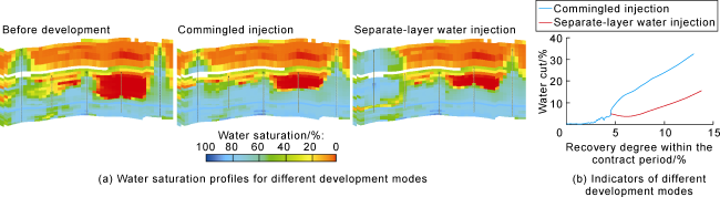
Fig. 7. Comparison of development effects of commingled injection and separate-layer water injection in the Mishrif Formation in Oilfield R in the Middle East. |
The Mishrif Formation in Oilfield A is 400 m thick, where six barriers have been identified, which are located at the top of the Mishrif Formation, the top and bottom of MB1, the middle part of upper MB2, the middle of MC, and the bottom of the Mishrif Formation. The barriers and baffles are developed mainly in MB1 (Fig. 8 ). The barrier at the top of MB1 is stable and capable of providing effective sealing; and MA is developed as an independent development unit through an injection-production well pattern. The baffles in MB1 vary in thickness from 0.5 m to 1.5 m and have poor stability, they can provide vertical sealing when stacked and be used as the basis for the subdivision of MB1. The barrier at MB1 bottom has a thickness of 1.0-3.5 m, distributional stability and good sealing capacity, thus separating MB1 with MB2. At the middle section of upper MB2 interval, there is a peat barrier with a single-layer thickness ranging from 1 m to 3 m. This barrier is stable and distributed across the entire field, separating the upper MB2 interval into two units with the upper unit as an independent development unit. A well-developed thin barrier exists in the middle part of MC, and the lower part of MC has poor petrophysical properties and low proportion of the geological reserves. For these reasons, the lower part of upper MB2, lower MB2 and MC were combined into one development unit for water injection. Considering the geological characteristics of the Mishrif Formation in Oilfield A and the characteristics of barriers and baffles in this formation, the development mode based on the fine stratigraphic framework was adopted.
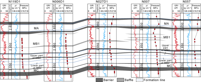
Fig. 8. Distribution of barriers and baffles in the Mishrif Formation in Oilfield A in the Middle East. |
It can be seen from the numerical simulation results that, for commingled injection in A Oilfield, the degree of recovery from the lower part of the reservoir is high, and that from the upper part is relatively low. The application of separate-layer waterflooding under the fine stratigraphic framework has significantly improved the degree of recovery from the upper part of the reservoir. For the same degree of recovery, the water cut of the separate-layer waterflooding method is always lower than that of the commingled waterflooding method. As the degree of recovery increases, the difference in water cut between the two methods becomes greater. In addition, the degree of recovery achieved by separate-layer waterflooding in the contract period is much higher than that achieved by commingled waterflooding (Fig. 9 ).
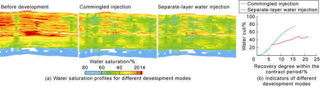
Fig. 9. Comparison of the effects of commingled injection and separate-layer water injection in the Mishrif Formation in Oilfield A in the Middle East. |
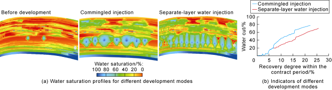
The Mishrif Formation in B Oilfield is nearly 350 m thick and highly heterogeneous, containing four well-developed barriers located at the top of the Mishrif Formation, CRII, the bottom of MB2, and the bottom of the Mishrif Formation (Fig. 10 ). CRII is a stable barrier that can provide effective sealing, separating MA and MB1, with MA considered as an independent development unit. There is no stable barrier between MB1 and MB2, but they differ greatly in terms of depositional environment, reservoir type and reservoir configuration. Despite the absence of stable barrier, MB1 and MB2 should be treated as two separate development units. The reservoir at the top of MB2 is thick and has good petrophysical properties, due to which commingled waterflooding will weaken the production performance of the underlying reservoir. Therefore, it should be treated as an independent development unit, and large-scale production can be rapidly achieved by deploying horizontal wells at a large spacing. A stable barrier is developed at the bottom of MB2, but there exists interlayer pressure transfer locally. Since the proportion of the geological reserves in MC is small, it is not worthwhile to deploy a separate well pattern for MC. For these reasons, the lower part of MB2 and MC were combined into one development unit. Considering the geological characteristics of the Mishrif Formation in B Oilfield and the characteristics of barriers and baffles, the development mode based on the deepened stratigraphic framework was adopted.
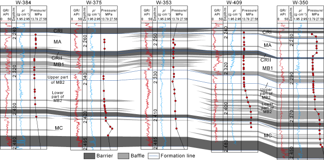
Fig. 10. Distribution of barriers and baffles in the Mishrif Formation in Oilfield B in the Middle East. |
The numerical simulation results show that, for commingled waterflooding in B Oilfield, the overall degree of recovery from the reservoir is relatively low with large amounts of unrecovered reserves in the lower part. The application of separate-layer waterflooding under the deepened stratigraphic framework has significantly improved the degree of recovery from various intervals of the formation. In particular, the application of horizontal wells in the lower part of the formation has significantly enhanced oil recovery. For the same degree of recovery in the early stage of oilfield development, the difference in water cut between separate-layer waterflooding and commingled waterflooding is relatively small. However, as the degree of recovery increases, such difference becomes greater. The water cut of the separate-layer waterflooding method is much lower than that of the commingled injection method, and the recovery degree achieved by the former in the contract period is much higher than that achieved by the latter (Fig. 11 ).
Fig. 11. Comparison of the effects of commingled injection and separate-layer water injection in the Mishrif Formation in Oilfield B in the Middle East. |
5. Conclusions
The thick carbonate reservoirs in the Iran-Iraq region of the Middle East are highly heterogeneous, where concealed baffles and barriers have developed. Under the commingled injection and production scheme, the recovery of geological reserves is highly unbalanced. Based on the oilfield development practices over the years, the concept of balanced separate-layer waterflooding in thick carbonate reservoirs was proposed to provide guidance for scientific and efficient oilfield development.
The techniques for identifying and characterizing concealed baffles/barriers and evaluating the sealing performance of concealed baffles/barriers were proposed. Based on the fine characterization and evaluation of baffles/barriers and the principles of development units division, a balanced separate-layer waterflooding technique characterized by the fine division of development units in complex thick carbonate reservoir and the implementation of “one strategy for one development unit” was proposed.
Three-dimensional injection-production system for balanced separate-layer waterflooding is the key to achieving the efficient development of complex thick carbonate reservoirs in Iran-Iraq region. In this study, three-dimensional injection-production systems with multiple layers in the vertical direction and water injected at separate stages were constructed from both spatial and temporal perspectives, the reasonable well types, well patterns and development technical strategies suitable for various zones/layers were determined. On this basis, three modes of balanced separate-layer waterflooding based on the conventional, fine and deepened stratigraphic frameworks were established with a view to achieving the efficient development of complex thick carbonate reservoirs in the Middle East.