

Introduction
The oil and gas exploration and development of China have entered the ultra-deep formation [1] and are advancing towards the extra-deep formation. In 2023, PetroChina planned to drill two extra-deep wells over 10 000 m, SDTK1 and SDCK1, with design depths of 11 100 m and 10 520 m, respectively. For extra-deep wells, especially those exceeding 10 000 m in depth, crucial technologies such as deviation control, rate of penetration (ROP) improvement and stability of drilling fluid, etc., face serious challenges, among which ensuring the dynamic safety of drilling tools is of utmost importance. The Well SG-3, an extra-deep well drilled in the former Soviet Union with a depth exceeding 10 000 m, failed to reach its designed depth after 23 years, primarily due to multiple incidents (27) of tool failure causing sidetracking (12) [2]. Therefore, ensuring the safety of the drill string is crucial for improving the efficiency of ultra-deep and extra-deep drilling operations.
During the drilling process of ultra-deep and extra-deep wells, the drill string with extremely large slenderness ratio operates in extreme working environment with huge axial force, high torque, high temperature and high pressure. It is also constrained by the narrow and long wellbore, resulting in complex vibration characteristics. This poses serious challenges to both the safety and efficiency of drilling [3⇓⇓-6]. The failure issues caused by drill string vibration have long been a focus of attention, with scholars around the world conducting in-depth researches on the dynamics characteristics of drill strings using various methods. Jansen [7] studied the whirl features of the bottom hole assembly (BHA) by using a concentrated mass model. Building upon this work, Di et al. [8] investigated the mechanism of pre-bending dynamic vertical and fast drilling technology, and analyzed the effects of weight on bit (WOB), surface rotation speed of drill string, and structural parameters of the BHA on the dynamic lateral force on the drill bit. Dykstra [9] developed a finite element model of drill string dynamics based on Hamilton's principle, considering the geometric and contact nonlinearities. Then the static solution, dynamic steady-state solution and transient solution of drill string were calculated respectively. Similarly, Zhu et al. [10] established a three-dimensional finite element model to study the dynamics of drill string in the full hole, and utilized the Wilson-θ stepwise integration to investigate large-scale nonlinear systems with uncertainties and dynamic boundaries. Hu et al. [11] established a finite element model based on spatial curved beam units to analyze the dynamics of a drill string over 7 000 m. Cheng et al. [12] established a multi-body dynamics model of drill string system based on the absolute nodal coordinate method, enabling the simulation of downhole dynamics characteristics such as viscous sliding, whirling, dynamic buckling and skipping of drill string. With the development of drill string vibration research and measurement technology, new vibration phenomena, such as high-frequency torsional oscillation, and new failure modes, such as electronic component failures continue to emerge [13⇓⇓-16], necessitating further expansion of drill string dynamic research to meet the safety requirements of practical drilling engineering.
In the drilling operations of ultra-deep wells in the Tarim Oilfield, the problem of secondary makeup of downhole drilling tool joints is often encountered, indicating the existence of downhole dynamic impact torque, which seriously affects the safety of drilling operations. But so far, there are only a few literatures on 3D mechanical analysis of tool joints in extra-deep wells. Chen et al. [17] studied the reasonable secondary shoulder clearance of double-shoulder drill pipe joints applicable to extra-deep wells. To ensure the safety of drilling tools in China's first extra-deep well over 10 000 m, SDTK1, some targeted research work has been carried out in Well GT1 with the same upper wellbore dimensions as Well SDTK1. One of these was to measure the amount of secondary makeup at the engaged shoulders of the threaded tool joint in Well GT1. Then the stress characteristics of drilling tool joint after secondary makeup were analyzed to provide a basis for searching for effective measures. While it is currently impossible to directly measure downhole dynamic impact torque, this study adopted equivalent impact torque to evaluate the load characteristics of the secondary makeup of drill tool joints. The circumferential relative offsets at the engaged shoulders of the drill tool joints were used to reflect the characteristics of the secondary makeup. And based on finite element analysis, the relationship equation between downhole equivalent impact torque and the relative offset of tool joints was established, serving as a prediction model for quickly determining downhole equivalent impact torque based on relative offsets. The model was verified again in the second drill string for 17" borehole section of Well SDTK1 and applied to predict downhole equivalent impact torque in subsequent drilling operations.
1. Three-dimensional elastic-plastic finite element modelling of drill collar joint
1.1. Analysis
Drill collar (DC) joints consist of internal threads (box) and external threads (pin) meshed by helical surfaces in three-dimensional space. The contact relationships between the shoulder surfaces of joints and those between the meshing surfaces of thread teeth are very complicated, and their 3D mechanical calculation involves highly nonlinear contact conditions. In this paper, the explicit dynamic calculation method is used to solve the dynamic equation, that is, the dynamic state of one incremental step is calculated without iteration, and the matrix inversion is not required to solve the motion equation. This approach enables effective calculation of the three-dimensional stress of DC joints under the action of complex loads. The dynamic equilibrium equation of the DC joint is:
The central difference method is used to solve the equation, and the acceleration and velocity can be expressed in terms of displacements [18]:
Substituting Eq. (2) and Eq. (3) into the dynamic equilibrium equation at time t yields the recursive equation for the central difference method:
$\begin{array}{c} \left(\frac{1}{\Delta t^{2}} \boldsymbol{M}+\frac{1}{2 \Delta t} \boldsymbol{C}\right) u_{t+\Delta t}=\boldsymbol{Q}_{t}-\left(\boldsymbol{K}-\frac{2}{\Delta t^{2}} \boldsymbol{M}\right) \boldsymbol{u}_{t}- \\ \left(\frac{1}{\Delta t^{2}} \boldsymbol{M}-\frac{1}{2 \Delta t} \boldsymbol{C}\right) \boldsymbol{u}_{t-\Delta t} \end{array}$
The node displacement ut+Δt at time (t+Δt) can be obtained by solving Eq. (4), and the element strain and element stress at time (t+Δt) can be obtained by substituting ut+Δt into the geometric equation and the constitutive equation.
1.2. Mesh division and material parameters
The secondary makeup process involves the displacement change of pin and box of drilling tool joints after makeup under complex loads. The second drill string used to drill 17" borehole section of Well GT1 in Tarim Oilfield included the following BHA: 17" (431.8 mm) polycrystalline diamond compact (PDC) bit + 241.0 mm Power-V + positive displacement motor (PDM) + 17" (431.8 mm) stabilizer + 9" (228.6 mm) DC × 3 joints + crossover sub+ 8" (203.2 mm) float valve +8" (203.2 mm) DC ×13 joints + 8" (203.2 mm) drilling jar + 8" (203.2 mm) flexible joint + 8" (203.2 mm) DC ×5 joints. The statistical data shows that the secondary makeup occurs mainly in BHA, which includes DCs of two outer diameter sizes: 8" (203.2 mm) and 9" (228.6 mm). Due to the weaker impact resistance of 8" DC joint compared to 9" DC joint, only a three-dimensional elastic-plastic finite element model of 8" DC joint is established. Nonlinear finite element analysis software, ABAQUS, was used to calculate the mechanical properties of 8" DC joint under the action of makeup torque, axial force and downhole impact torques, and to analyze the downhole makeup characteristics of DC joint under different downhole impact torques.
The basic dimensions of 8" NC56 DC joint are shown in Table 1. In order to accurately simulate the stress characteristics of DC joint under composite loads, hexahedral mesh is used to ensure the calculation accuracy. At the same time, the spiral angle of thread teeth is considered, and fine meshes are arranged in the meshing area of thread teeth. The finite element model comprises 66.2×10⁴ elements and 75.7×10⁴ nodes, utilizing cell type C3D8I for calculation, as illustrated in Fig. 1. Contact is defined on engaged surfaces at the shoulders and between threads to simulate the interaction between pin and box under complex loads. Distributed node coupling is established at the end face of pin to apply the external loads, while kinematic node coupling is established at the end face of box to apply the constraints.
Table 1. Dimensions of NC56 DC joints |
| Parameter | Value | Parameter | Value |
|---|---|---|---|
| External diameter | 203.2 mm | Thread taper | 1/6 |
| Internal diameter | 71.4 mm | Thread type | 0.038R |
| Large end diameter of pin | 149.2 mm | Large end diameter of taper hole of box | 150.8 mm |
| Cone length of pin | 127.0 mm | Cone length of box | 142.9 mm |
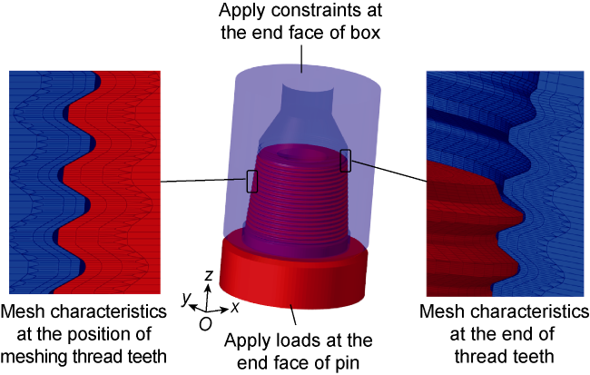
Fig. 1. Schematic diagram of 3D finite element model of DC joint (red colour represents the pin, blue colour represents the box). |
The material used for 8" DC joint is 4145H steel, and a standard tensile testing was conducted on the specimens made of this material. The specimens were processed according to the ASTM E8 standard method for tensile testing of metallic materials [19], and the mechanical properties of the material were tested under uniaxial tensile conditions at room temperature to obtain the nominal stress and nominal strain of the material, which were then converted into true stress, true strain, and plastic strain (Table 2 ). According to the experimental data, the density of the material used for DC joint is 7 850 kg/m³, the modulus of elasticity is 2.06×10⁵ MPa, the Poisson's ratio is 0.29, the yield strength is 758.0 MPa, and the strength limit is 1 084.8 MPa. Considering the effect of the thread grease with a zinc powder mass fraction of 40%-60%, the coefficient of friction between the mating surfaces, including those between the threads and between the shoulder surfaces was taken as 0.08 [17].
Table 2. True stress-plastic strain relationship |
| True stress/ MPa | Plastic strain | True stress/ MPa | Plastic strain | True stress/ MPa | Plastic strain |
|---|---|---|---|---|---|
| 758.0 | 0 | 953.7 | 0.025 | 1 063.6 | 0.065 |
| 790.1 | 0.000 5 | 971.3 | 0.030 | 1 072.4 | 0.070 |
| 818.3 | 0.001 0 | 987.6 | 0.035 | 1 079.8 | 0.075 |
| 878.5 | 0.006 0 | 1 003.3 | 0.040 | 1 086.1 | 0.080 |
| 891.3 | 0.009 0 | 1 017.6 | 0.045 | 1 091.2 | 0.085 |
| 905.2 | 0.012 0 | 1 030.9 | 0.050 | 1 095.1 | 0.097 |
| 920.8 | 0.016 0 | 1 043.0 | 0.055 | ||
| 940.1 | 0.021 0 | 1 054.3 | 0.060 |
The stress distribution of DC joint is not uniform, and when the external load reaches a specific value, the region with severe stress concentration enters the plastic state firstly. At this point, the linear elastic stress-strain relationship is no longer applicable. A nonlinear stress- strain relationship was introduced, and the von Mises yield criterion was applied [18]:
where
The initial yield stress σso of the material can be obtained through uniaxial tensile experiments. The von Mises flow law was adopted to describe the relationship between the components of plastic strain increment and the components of stress increment in each direction after yielding. The isotropic hardening model was used to simulate the material hardening characteristics of the drilling tool joints under the action of complex loads.
The whole finite element analysis consists of three analysis steps: in the first step, the NC56 DC joint is preloaded with makeup torque, which is set to 65 kN·m by reference to the API (American Petroleum Institute) standard. Considering that the DC joint near the bit is subjected to axial compression load under the action of dynamic WOB, an axial compression load of 120 kN is imposed on the model in the second analysis step. The third analysis step applies a downhole equivalent impact torque (0-120 kN·m) on the model to analyze the relative rotation between the pin and box of DC joint under the action of different downhole equivalent impact torques. It should be noted that the equivalent impact torque is different from the actual downhole dynamic impact torque and is an equivalent torque under quasi-static loading conditions, that is, the two produce an equivalent amount of makeup.
2. Three-dimensional elastic-plastic finite element analysis for DC joint
2.1. Three-dimensional stress characteristics of DC joint under the action of makeup torque
Under the action of a makeup torque of 65 kN·m, the von Mises stress distribution cloud diagram of DC join is shown in Fig. 2. The results show that the stress distribution of DC joint is not uniform under preload, and the stress level is high at the shoulder and the meshing thread teeth near the shoulder. The maximum von Mises stress is 878.58 MPa and appears at the first meshing thread tooth near the shoulder of pin.
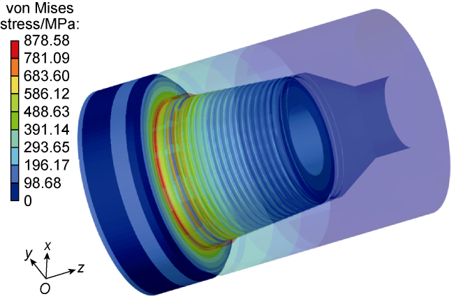
Fig. 2. von Mises stress distribution of NC56 DC joint under the action of makeup torque. |
A cylindrical coordinate system was established at the rotation center of DC joint. The displacement calculation results were then converted to cylindrical coordinates to obtain the circumferential relative displacement of DC joint and analyze the relative rotation between pin and box under the action of makeup torque (Fig. 3 ). In the process of makeup, the end of the box of DC joint is fixed under constrains, and the end of the pin is subjected to makeup torque. Thus, the pin is processed and preloaded relatively to the box, so as to generate relative displacement. Under the action of 65 kN·m makeup torque, the circumferential relative displacement at the shoulder of pin and box of DC joint is about 50.0 mm. Here, the circumferential relative displacement caused solely by the makeup torque is referred to as the reference offset, while the incremental offset caused by other loads on this basis is referred to as the relative offset.
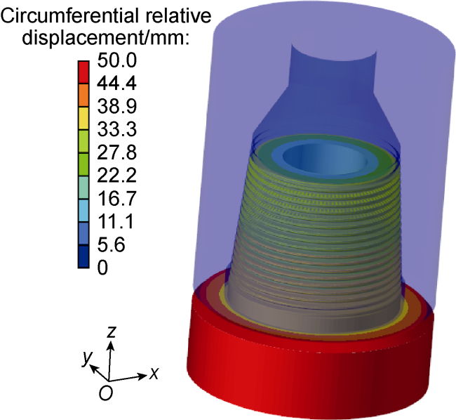
Fig. 3. Rotary displacement distribution of DC joint. |
2.2. Stress characteristics of DC joint under the action of makeup torque and axial compression loads
In actual drilling operations, the DC joints near the bit are subjected to relatively large axial compression load, while those near the neutral point of drill string bear relatively small axial compression load. Therefore, it is necessary to investigate whether the applied axial load will affect the stress characteristics of DC joints after applying the makeup torque. An axial compression load of 120 kN was applied to DC joint based on the 65 kN·m makeup torque, and the von Mises stress distribution of DC joint in this case is shown in Fig. 4. The results show that compared with the application of makeup torque alone (Fig. 2 ), the stress distribution of DC joint did not change much with the addition of axial compression load. The maximum von Mises stress still appeared in the first meshed thread tooth near the shoulder of pin, with a stress value of 880.35 MPa. The same method was adopted to establish a cylindrical coordinate system and extract the circumferential relative displacement. Under the action of 65 kN·m makeup torque and 120 kN axial compression load, the circumferential relative displacement at the shoulders of pin and box is 50.0 mm, which is the same as the reference offset. This indicates that the 120 kN axial compression load does not cause a relative displacement between pin and box, and the relative offset is zero.
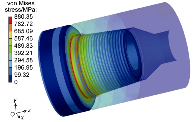
Fig. 4. von Mises stress distribution of NC56 DC joint under the action of makeup torque and axial compression loads. |
The contact pressure characteristics between the engaged surfaces of DC joints under different downhole equivalent impact torques at the axial compression load of 0 and 120 kN are shown in Fig. 5. It can be observed that the application of compression load has a minor effect on the contact pressure on engaged surfaces between thread teeth and at the shoulders. Moreover, the increase of axial force does not significantly alter the stress characteristics of the joint. Therefore, using a 120 kN axial compression load for offset calculations can accurately represent the actual situation with minimal error.
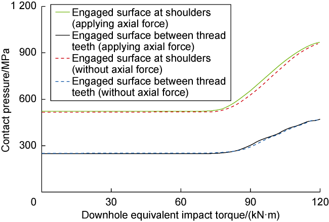
Fig. 5. Contact pressure on the engaged surfaces of NC56 DC joint under different axial forces. |
2.3. Three-dimensional stress characteristics of DC joint and relative offset of pin and box under the action of downhole equivalent impact torques
The displacement and stress distribution characteristics of DC joint were obtained by applying different downhole equivalent impact torques to the model on the basis of applied makeup torque and axial compression load. When the downhole equivalent impact torque is 60, 90, and 120 kN·m, the von Mises stress distribution in the pin and box of DC joint is shown respectively in Fig. 6. It can be observed that the larger the downhole equivalent impact torque, the higher the von Mises stress level at the shoulder and the thread teeth near the shoulder. The stress peaks all appear on the first meshed thread tooth near the shoulder of pin, and the peak von Mises stresses are 878.8, 917.3, and 985.2 MPa corresponding to the downhole equivalent impact torques of 60, 90, and 120 kN·m, respectively.
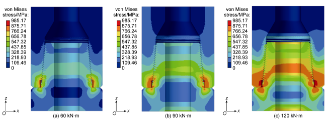
Fig. 6. von Mises stress distribution in DC joint under different downhole equivalent impact torques. |
The relative rotations between pin and box under different downhole equivalent impact torques are shown in Fig. 7. The results show that the maximum values of circumferential relative displacements at the shoulders of pin and box of DC joints under the downhole equivalent impact torque of 60, 90, and 120 kN·m are 50.1, 61.8, and 120.2 mm, respectively, and the relative offsets are 0.1, 11.8, and 70.2 mm, respectively. The loading of impact torque is a continuous process, so the actual calculation involves a large number of points, and will take up a lot of time. Considering that the relative offset in the actual situation is generally less than 40.0 mm, this study regressed the calculation results with reference to the range of this offset to obtain the relationship curve between the downhole equivalent impact torque and the relative offset at the shoulders of pin and box of DC joints (Fig. 8 ).
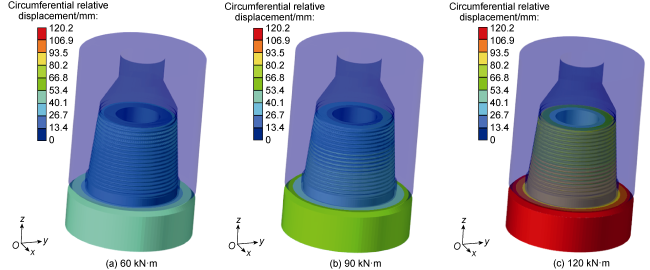
Fig. 7. Distribution of circumferential relative displacement at the shoulders of pin and box of DC joints under different downhole equivalent impact torques. |
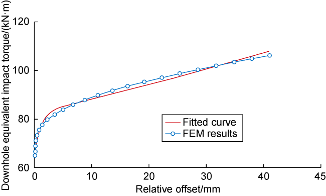
Fig. 8. Relationship between the relative offset at the shoulders of pin and box of NC56 DC joints and downhole equivalent impact torques. |
As can be seen from the Fig. 8 , when the downhole equivalent impact torque is less than 65 kN·m, the relative offset at the shoulders of pin and box of DC joints is almost zero, and the joints are still in a good state under preload. When the downhole equivalent impact torque exceeds 65 kN·m, the preload equilibrium state of the DC joints is broken, and the relative offset between pin and box is obvious. Therefore, the data corresponding the downhole equivalent impact torques exceeding 65 kN·m were fitted to obtain Eq. (6). The correlation coefficient of the fitted curve is 0.998, and the total number of calculation points involved in the regression is 23.
(T≥65 kN·m)
3. Prediction of the downhole equivalent impact torque acting on drill tool joint
According to Eq. (6), the downhole equivalent impact torque can be determined according to the circumferential relative offset at shoulders of pin and box of drill tool joints. Therefore, the 8" DC joints in the BHA were marked with a scratch mark before tripping in the drill string, and the offset of each scratch mark was measured after trapping out of drill string to obtain the relative offset. During tripping in the second drill string for 17" borehole section of Well GT1, the drill bit, Power-V, centralizer and 17" DCs were fastened with B-type tongs and other drill tools were fastened with hydraulic power tongs according to the recommended makeup torque of API standard to ensure that the measurement results were not affected by the makeup torque.
The completion depth of Well GT1 is 5 180 m. The depth of 17" borehole ranges from 530 m to 3 580 m, and the borehole section drilled with the second drill string ranges from 2 877 m to 3 580 m. During drilling, the WOB ranged from 60 kN to 120 kN, and the surface rotation speed of drill string was set to 60 r/min. After tripping out drill string, it was found that the relative offset at the shoulders of pin and box of NC611×NC560 crossover sub and 8" float valve joint was 13 mm, and the relative offset at the shoulder of pin and box of 8" float valve joint and 8" DC joint was 4 mm (Figs. 9 and 10 ).
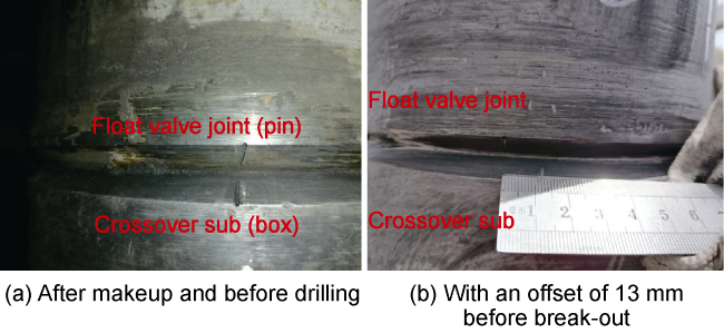
Fig. 9. Offset at the shoulders of crossover sub and float valve joint. |

Fig. 10. Offset at the shoulders of float valve joint and 8" DC joint. |
The field test results show that the DC joints at different locations in the BHA have secondary make-up feature. Additionally, the circumferential relative offsets at shoulders of pin and box of DC joints at different positions are different, demonstrating that the joints at different locations subject to different impact torques, which are greater than the makeup torque. According to Eq. (6), when the relative offset between crossover sub and float valve joint is 13 mm, the corresponding downhole equivalent impact torque is about 90.05 kN·m, closely matching the on-site breakout torque of 90.00 kN·m, resulting in a 0.06% relative error between the theoretical calculation and the measured breakout torque. Similarly, the measured offset between float valve joint and 8" DC joint is 4 mm, corresponding to a downhole equivalent impact torque of 84.35 kN·m. However, the on-site breakout torque of this joint is about 80.00 kN·m, resulting in a 5.44% relative error between the theoretical calculation and the measured result. These results validate the accuracy of the calculation method proposed in this study.
The Well SDTK1 is spudded in on May 30, 2023 and commenced with second run of drilling for the 17" (431.8 mm) borehole on June 1, 2023. The BHA used was: 17" (431.8 mm) PDC drill bit + 9 1/2" (241.0 mm) Power-V + PDM + 17" (431.8 mm) stabilizer + 9" (228.6 mm) DC × 6 joints + crossover sub + 8" (203.2 mm) DC ×6 joints + float valve + 8" (203.2 mm) DC×6 joints + 8" (203.2 mm) drilling jar + 8" (203.2 mm) DC ×3 joints. The WOB and surface rotation speed used were 60 kN and 60 r/min, respectively. In order to improve the torsional resistance of the joint, the makeup torque of some 8" DC joints was increased to 71 kN·m. Before tripping in the drill string, scratch marks were made at some 8" DC joints, and after tripping out drill string, it was found that the marks on all 8" DC joints had shifted. Table 3 lists the relative offsets at the shoulders of pin and box of some 8" DC joints.
Table 3. Relative offset and corresponding downhole equivalent impact torque at the shoulders of pin and box of DCs in second run of drilling operation for 17" borehole of Well SDTK1 |
| Scratch mark location on 8" DC joint | Thread type | Makeup torque/ (kN·m) | Relative offset/ mm | Breakout torque/ (kN·m) | Downhole equivalent impact torque/ (kN·m) | Relative error between downhole equivalent impact torque and breakout torque/% |
|---|---|---|---|---|---|---|
| Lower end of the 3rd DC | NC56 | 71 | 18 | 94 | 93.03 | −1.03 |
| Lower end of the 7th DC | NC56 | 69 | 18 | 101 | 93.03 | −7.89 |
| Lower end of the 8th DC | NC56 | 71 | 15 | 91 | 91.23 | 0.25 |
| Lower end of the 10th DC | NC56 | 71 | 19 | 96 | 93.64 | −2.46 |
As demonstrated in Table 3 , the relative offset of the lower end of the third 8" DC (upwards from the drill bit in drill string) is 18 mm. According to Eq. (6), the corresponding downhole equivalent impact torque is about 93.03 kN·m, with a relative error of only −1.03% to the breakout torque. The relative offsets of the joints at lower end of the 8th 8" DC and the 10th 8" DC are 15 mm and 19 mm, respectively. The corresponding downhole equivalent impact torques are 91.23 kN·m and 93.64 kN·m, with relative errors of 0.25% and −2.46% with respect to the breakout torque, respectively. The make-up torque at the connection between the lower end of the 7th DC and the float valve (i.e., the upper end of the float valve) is 69 kN·m, with a measured relative offset of 18 mm. The calculated downhole equivalent impact torque is 93.03 kN·m, with a relative error of −7.89% to the breakout torque of 101 kN·m. This relative error is the largest among all measurement points, which may be attributed to the different makeup torque and the existence of float valve. These results once again demonstrate the high prediction accuracy of Eq. (6). In actual operation, the fluctuation range of data measured by iron roughneck during breakout of joint is large, and it is time-consuming and laborious to obtain accurate breakout torque of joint. However, by using Eq. (6), the downhole equivalent impact torque can be quickly obtained according to the relative offset. By measuring the relative offset of 8" DC joints in the third drill string for 17" borehole section of Well SDTK1, the downhole equivalent impact torques were quickly calculated (Table 4 ).
Table 4. Relative offset and corresponding downhole impact torque at the shoulders of pin and box of 8" NC56 DC joints in third drill string for 17" borehole section of Well SDTK1 |
| Scratch mark location on 8" DC joint | Makeup torque/ (kN·m) | Relative offset/ mm | Downhole equivalent impact torque/ (kN·m) |
|---|---|---|---|
| Lower end of the 3rd DC | 71 | 12 | 89.17 |
| Lower end of the 5th DC | 71 | 19 | 93.16 |
| Lower end of the 6th DC | 71 | 22 | 94.93 |
| Lower end of the 9th DC | 71 | 1 | 75.78 |
The above results indicate that the 8" DC joints in the third drill string for 17" borehole section of SDTK1 well were subjected to significant downhole impact torque, posing a safety hazard to the DC joints. Additionally, DCs at different positions bear different downhole impact torques, indicating that the movement characteristics of DCs in the downhole are very complicated. Moreover, it suggests that the relative offset is influenced by several factors, including the impact torque, the measurement accuracy, the accurate application of makeup torque according to the API standard and the contact state between the joint threads.
The method proposed in this study has good application effect in subsequent drilling in Well SDTK1, and the downhole equivalent impact torques of DC joints are well evaluated. For example, in the drilling of 9 1/2" borehole section of Well SDTK1, the secondary makeup phenomenon of tool joints appeared in multiple runs, and many micro-cracks were formed in DC joints or heavy weight drill pipe joints. The test results show that 17 joints of 21 joints of 7" DCs used in the fourth drill string had micro-cracks in the internal threads of the DC joints (Fig. 11 ). In order to eliminate the hidden danger of DC joint failure and ensure downhole safety, the following three measures have been taken: (1) Replace the DCs with micro-cracks; (2) On the premise of ensuring that the make-up torque meets the requirements, use the DS56 double-shoulder tool joint with higher torque resistance [20], which can improve the resistance to impact torque of drill tool joints and reduce the occurrence frequency of micro-cracks greatly; (3) Optimize the structural and operation parameters of the drill string to reduce drill string vibration and minimize downhole impact torque.

Fig. 11. Photo of micro-cracks on the internal thread of the 7" NC56 DC joint. |
4. Conclusions
Under complex loads, the stress distribution in the DC joint is uneven, with the von Mises stress level relatively high at the shoulder and the thread teeth near the shoulder, making it the weakest parts of the DC joint. For 8" DC joint pre-tightened with the make-up torque recommended by API standards, when the downhole equivalent impact torque exceeds 65 kN·m, the preload balance of the joint is disrupted, leading to secondary makeup phenomenon of the joint. The relative offset at the shoulders of pin and box becomes larger with the increase of the downhole equivalent impact torque. Finite element analysis can be utilized to inverse the downhole equivalent impact torque based on the relative offset at the shoulders of pin and box, thus forming a rapid prediction method for the downhole equivalent impact torque. The test and calculation results show there existing large impact torques on the drill string of Well SDTK1, and the loads borne by the drill tool are very complicated. Effective measures should be taken to enhance the impact torque resistance of the joints or reduce the downhole impact torque. Firstly, double-shoulder tool joints should be used to replace single-shoulder tool joints. Secondly, structural and operation parameters of the drill string should be optimized to reduce drill string vibration and minimize downhole impact torque.
Nomenclature
a(t)—node acceleration vector of the system at time t, m/s2;
C—damping matrix of the system, N/(m·s−1);
—stress function;
K—stiffness matrix of the system, N/m;
M—mass matrix of the system, kg;
Q(t)—node load vector of the system at time t, N;
sij—deviatoric stress tensor, MPa;
t—time, s;
Δt—time step of calculation, s;
T—downhole equivalent impact torque on DC joint, kN·m;
u—displacement of the system, m;
u(t)—node displacement of the system at time t, m;
v(t)—node velocity vector at time t, m/s;
x, y, z—three directions in the cylindrical coordinate system;
δij—Kronecker symbol, dimensionless;
ξ—relative offset at the shoulders of pin and box of DC joint, mm;
σm—average normal stress, MPa;
σso—initial yield stress of the material, MPa;
σ11, σ22, σ33—principal stresses in 3 directions, MPa.
subscript:
i, j—values of 1, 2 and 3 can be taken to show the different stress components.