

Introduction
Shale oil and gas development commonly encounters challenges such as low initial production, rapid production decline rates, and low recovery degree of single well [1⇓⇓⇓⇓-6]. In the context of horizontal well hydraulic fracturing with smaller cluster spacing as a predominant reservoir stimulation technique, the development of shale beddings and natural fractures (NFs), coupled with reservoir heterogeneity, presents challenges in achieving balanced initiation and propagation of fractures of densely multi- cluster perforation [7⇓⇓⇓-11]. Within this framework, the com-bination of intra-fracture temporary plugging (IFTP) and intra-segment temporary plugging (ISTP) emerges as a pivotal strategy for enhancing hydraulic fracture (HF) complexity and achieving more uniform distribution [12-13]. Therefore, elucidating the mechanisms governing the propagation and diversion of multi-cluster fractures from temporary plugging in horizontal well holds significant implications for optimizing the applicability of temporary plugging and diversion fracturing (TPDF).
In order to explore the propagation law of multi-fractures after TPDF, numerous scholars have conducted laboratory experiments and theoretical research. They have found that the effectiveness of temporary plugging is influenced by reservoir conditions (such as in-situ stress state, beddings/natural fractures, etc.) and operational parameters (such as temporary plugging agent (TPA) type, TPA particle size, TPA concentration, displacement, and fracturing fluid viscosity, etc.) [14⇓⇓⇓⇓⇓-20]. Zou et al. [21], Zhou et al. [22], and Chen et al. [23] suggested that the horizontal stress difference and inter-cluster stress difference are the primary controlling factors determining the diversion effects of HF by temporary plugging within fractures and within segments. The larger the horizontal stress difference or inter-cluster stress difference, the more difficult it is for fractures to divert, requiring more TPAs, earlier plugging timing and more plugging cycles. Tang et al. [24] indicated that the higher the density or the azimuth angle of NFs, the later the optimal timing for temporary plugging. Lu et al. [25] proposed that the efficiency of NF opening is influenced by the plugging strength and the approaching angle of NFs. Forming an effective plugging zone is crucial for inducing HF diversion. Guo et al. [26] proposed that the primary controlling factors affecting the formation mode of the plugging zone are the ratio of particle size to fracture width, and the displacement and viscosity of carrying fluid. Li et al. [27] pointed out that under the influence of TPA particle concentration, the plugging zone exhibits different bridging modes, with high concentration conditions tending towards dual-particle bridging and low concentration conditions tending towards single-particle bridging. Different diverted fractures are formed in different plugging positions. Li et al. [28] found that the larger the horizontal stress difference, the closer the initiation position to the fracture tip. Yuan et al. [29] proposed a method based on the normal width of the fracture to describe the characteristics of the plugging position, suggesting that the narrow region inside the fracture is the characteristic plugging position. Wang et al. [30] discovered that when the plugging occurs at the fracture tip, the diverted fracture is perpendicular to the main fracture; and when the plugging occurs in the middle of the fracture, the fracture morphologically exhibits a "S" shape. Hu et al. [31] found that the closer the plugging position is to the fracture mouth, the more balanced the overall propagation of multi-cluster fractures. Zhang et al. [32] suggested that the primary controlling factor influencing the plugging position and the propagation of diverted fractures is TPA concentration. Regarding the mechanism of temporary plugging for pressure buildup, Wang et al. [33] and Shi et al. [34] qualitatively pointed out that plugging at the fracture mouth changes the circumferential stress around the wellbore, plugging inside the fracture changes the closure stress of the fracture, and plugging at the fracture tip hinders the conduction of fluid stress and achieves fracture arrest.
The above-mentioned studies on TPDF simulations mainly focus on open-hole completions for vertical/horizontal wells [16,32 -33,35⇓ -37] or polyvinyl chloride casing perforation completions [38], which differ significantly from the on-site perforation completion methods. In addition, there is currently limited experimental research on the influence of the number of single-cluster perforations in horizontal wells on the propagation of multi-fractures, and there is still controversy over the primary controlling factors affecting the diversion effect of HFs in shale formation. This paper adopted the shale outcrop of Silurian Longmaxi Formation in the Sichuan Basin, SW China, to carry out true triaxial TPDF simulation experiment of horizontal well with multi-cluster sand jetting perforation, to study the effects of TPA particle size, TPA concentration, number of single-cluster perforations, and cluster numbers on the initiation, propagation, and diversion of multi-fractures. The aim is to provide a basis for the design of key parameters in TPDF processes for shale reservoirs with developed beddings.
1. TPDF simulation
The experimental rock samples were obtained from the outcrop of Silurian Longmaxi Formation shale in the Sichuan Basin (underground mine in Changning County). The mineral compositions of the shale are predominantly silica and clay minerals, with quartz content of 51.8%, clay mineral content of 32.8%, and carbonate and pyrite contents of 9.5% and 5.9%, respectively. The samples exhibit widespread development of beddings and NFs filled with pyrite and carbonate mineral (Fig. 1 ). The matrix porosity of the rock samples ranges from 4.4% to 5.1%, with strong anisotropy in permeability and mechanical parameters. The formation permeability parallel and perpendicular to the bedding direction are 0.000 236× 10−3 μm2 and 0.000 014×10−3 μm2, respectively. The elastic moduli parallel and perpendicular to the bedding direction are 49.1 GPa and 40.3 GPa, respectively, and the tensile strengths parallel and perpendicular to the bedding direction are 6.8 MPa and 9.2 MPa, respectively. The permeability of mineral-filled NFs is (0.001 22-0.010 63)× 10−3 μm2, with tensile strengths ranging from 4.7 MPa to 7.2 MPa. Overall, bedding planes (BPs) and NFs serve as high-permeability mechanical weak surfaces.
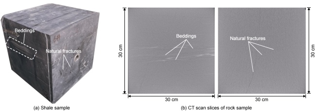
Fig. 1. Distribution of beddings and NFs in shale sample. |
The large shale outcrop was cut into 30 cm×30 cm×30 cm cubic rock samples along parallel and perpendicular bedding directions. To simulate horizontal well fracturing, holes with a diameter of 30 mm and a length of 26 cm were drilled at the center of the sample surface along the parallel bedding direction. Steel pipes with inner diameter of 22 mm and outer diameter of 27 mm were selected to simulate casing, and threads were added to the outer wall to enhance bonding strength. High- strength epoxy resin was then used to bond the steel pipes to the hole walls. Subsequently, the perforation gun of the hydraulic sand jetting perforation equipment was inserted into the wellbore to the predetermined depth. The perforation gun was rotated to align the nozzle with the desired perforation direction, fixed in place, and the high-pressure sand-carrying pump was turned on to complete the perforation (Fig. 2 ). After the sand-carrying pump was turned off, the perforation gun was rotated again to complete the remaining perforations in the cluster. Starting from the cluster closest to the toe, the perforation gun was gradually lifted step by step to complete the perforation of all clusters. The duration of sand-carrying for each individual perforation process (the perforation equipment allows for manual control of whether it carries sand, in which the jet cannot penetrate the wellbore or the rock matrix without carrying sand; The perforation is effective only during the sand-carrying period) was kept constant at 1 min to ensure uniformity of the perforation hole sizes (diameter of 4 mm, depth of 10 mm). Multiple clusters with different numbers of perforations or different phases of perforation were completed using the above method (Fig. 3 ).
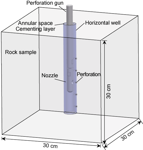
Fig. 2. Schematic diagram of hydraulic sand jetting perforation method. |
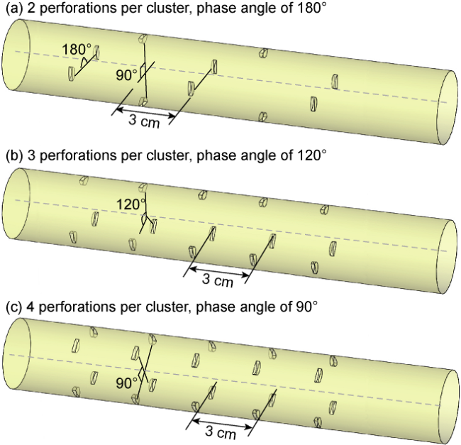
Fig. 3. Schematic diagram of perforation with different parameters. |
The experiment utilized an integrated true triaxial sand fracturing simulation device [39-40]. Key experimental parameters were determined based on the performance of the experimental equipment and the similarity criteria, including three-axis stress (maximum horizontal principal stress σH, minimum horizontal principal stress σh and vertical stress σv), displacement, and fracturing fluid viscosity, etc. To make the experimental results closer to reality, the actual in-situ stress conditions of a certain block in the Longmaxi Formation shale reservoir were included in the experiment [39,41 -42], which follows a stress mechanism of strike-slip reverse faulting (σH>σv>σh). Additionally, the relative values of 3D in-situ stress in the reservoir were taken into account, i.e., a vertical stress difference of 10 MPa and horizontal principal stress difference of 15 MPa, to set the experimental vertical stress at 20 MPa, maximum horizontal principal stress at 25 MPa, and minimum horizontal principal stress at 10 MPa. To simulate the on-site process of viscous-dominated fracture propagation, the main injection parameters were calculated using similarity criteria [43⇓⇓-46], as shown in Eqs. (1) and (2). Considering on-site displacements ranging from 14 m3/min to 18 m3/min, fracturing fluid viscosity from 5 mPa·s to 10 mPa·s, and fracture propagation characteristic radius from 15 m to 25 m (i.e., assessing half-fracture height), while the experimental fracture propagation characteristic radius was approximately 0.15 m (i.e., half the length of the rock sample), the experimental displacement was calculated to be approximately 200 mL/min.
According to the geometric similarity criteria [47-48], considering an on-site cluster spacing of 5 m to 15 m and a fracture half-length of 100 m to 150 m, with the experimental fracture half-length approximately 0.15 m (half the length of the rock sample), the experimental cluster spacing can be calculated to be approximately 2 cm to 6 cm using Eq. (3). In this study, the fixed-face perforation method was adopted [49-50], and based on an experimental horizontal well section length of 26 cm, the number of perforation clusters per segment was set in the range of 3-7.
The main experimental steps are as follows: (1) The rock sample is placed in a triaxial core chamber, and a variable frequency loading method is employed. The minimum horizontal principal stress, maximum horizontal principal stress, and vertical stress are successively applied along the X, Y and Z axes using a triaxial hydraulic servo system until reaching predetermined values, which are then maintained stable. (2) The fracturing process is divided into three phases: conventional fracturing (CF) phase (pre-plugging phase), IFTP phase, and ISTP phase. Based on previous experimental experience, fine-grained TPAs tend to migrate into the fracture to form plugs, while coarse-grained TPAs tend to plug at the fracture mouth or perforation orifice. Therefore, fine-grained TPAs are mainly used in the test of the IFTP phase, while coarse-grained TPAs are mainly used in the test of the ISTP phase. Fracture generation during each fracturing phase is identified based on the distribution of different colored tracers combined with acoustic emission localization. (3) Micro-CT scanner is used to scan the grayscale images of the rock sample. The rock core is reconstructed using high-precision CT data. Combined with the tracer distribution and rock sample dissection results, the HFs, opened NFs and beddings, and proppant/TPA distribution inside the rock sample were comprehensively identified and analyzed.
In the CF phase, the proppants sized between 75 μm and 106 μm (140-200 mesh) were adopted to maintain a certain width of HFs. The experiment disregarded the process of TPAs migrating from the perforation orifice to the point with critical fracture width of the bridge. It focused on the possibility of TPAs forming a plugging zone at the critical width of the fracture. To mitigate potential experimental biases arising from differences in TPA particle size and performance, on-site TPAs were utilized in the experiment, primarily including small- sized TPAs ranging from 125 μm to 180 μm (80-120 mesh) and 180 μm to 850 μm (20-80 mesh), as well as large-sized TPAs ranging from 1 mm to 2 mm and 1 mm to 3 mm.
A total of 13 sets of experiments were designed. Among them, samples 1# to 5#, 6# to 8#, and 9# to 11# were respectively utilized to analyze the effects of TPA particle size, TPA mass concentration, and the number of single-cluster perforations on the initiation, propagation and diversion of multi-cluster fractures. Samples 7#, 12#, and 13# were used to analyze the impact of cluster numbers. The specific plans are detailed in Table 1.
Table 1. Experimental scheme |
| Rock sample No. | Parameters of TPA for IFTP | Parameters of TPA for ISTP | Perforation number of single cluster | Cluster number | ||||
|---|---|---|---|---|---|---|---|---|
| Particle size/μm | Dosage/g | Mass concentration/ (g·L−1) | Particle size/mm | Dosage/g | Mass concentration/ (g·L−1) | |||
| 1# | 125-180 | 60 | 60 | 1-2 | 40 | 40 | 3 | 5 |
| 2# | 180-850 | 60 | 1-3 | 40 | ||||
| 3# | 125-180 | 30 | 1-2 | 20 | ||||
| 180-850 | 30 | 1-3 | 20 | |||||
| 4# | 125-180 | 50 | 1-2 | 35 | ||||
| 6 mm fiber | 10 | 6 mm fiber | 5 | |||||
| 5# | 125-180 | 30 | 125-180 μm | 20 | ||||
| 1-2 mm | 30 | 1-3 | 20 | |||||
| 6# | 125-180 | 20 | 40 | 1-2 | 10 | 20 | 3 | 5 |
| 180-850 | 20 | 1-3 | 10 | |||||
| 7# | 125-180 | 30 | 60 | 1-2 | 20 | 40 | ||
| 180-850 | 30 | 1-3 | 20 | |||||
| 8# | 125-180 | 40 | 80 | 1-2 | 30 | 60 | ||
| 180-850 | 40 | 1-3 | 30 | |||||
| 9# | 125-180 | 30 | 60 | 1-2 | 20 | 40 | 2 | 5 |
| 180-850 | 30 | 1-3 | 20 | |||||
| 10# | 125-180 | 30 | 1-2 | 20 | 3 | |||
| 180-850 | 30 | 1-3 | 20 | |||||
| 11# | 125-180 | 30 | 1-2 | 20 | 4 | |||
| 180-850 | 30 | 1-3 | 20 | |||||
| 12# | 125-180 | 30 | 60 | 1-2 | 20 | 40 | 3 | 3 |
| 180-850 | 30 | 1-3 | 20 | |||||
| 13# | 125-180 | 30 | 1-2 | 20 | 7 | |||
| 180-850 | 30 | 1-3 | 20 | |||||
2. Factors influencing the propagation of multi-cluster fractures
The influence of TPA particle size, TPA mass concentration, single-cluster perforation number, and cluster number on the TPDF effect of multi-cluster sand jetting perforation was evaluated with the pressure increase amplitude, HF quantity and HF complexity after TPDF as indicators. Based on the post-fracturing HF occurrence of rock samples, three representative HF orientations can be summarized: transverse fractures extending perpendicular to the wellbore, longitudinal fractures extending along the wellbore axis, and horizontal fractures extending along beddings (Fig. 4 ). When encountering beddings or NFs, HFs exhibit various behaviors, including penetration, deviation and termination. During CF phase, HFs tend to initiate in low-strength beddings near the wellbore, resulting in difficulties in subsequent fracture penetration and forming simple fracture morphology overall (as seen in samples 5# and 10#). However, when weak BPs are distributed away from the wellbore or NFs are present, HFs can propagate through beddings or NFs, forming complex branched fractures (as observed in samples 1#, 3# and 6#).
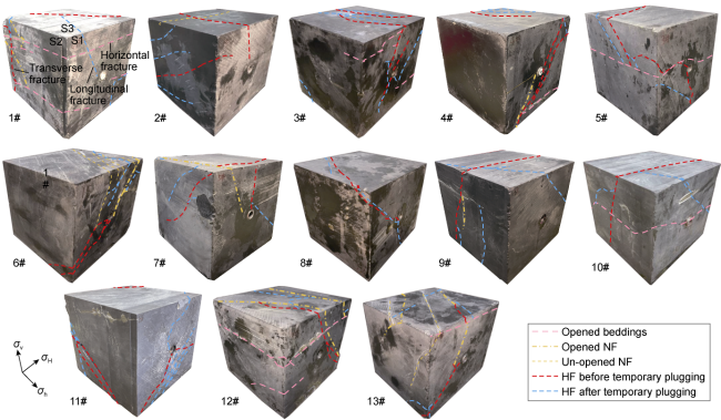
Fig. 4. Fracture morphology on rock sample surface after TPDF. |
2.1. Influence of TPA particle size on the propagation of multi-cluster fractures
Sample 1# utilized TPA with particle sizes ranging from 125 μm to 180 μm, while sample 2# used TPA with particle sizes ranging from 180 μm to 850 μm, corresponding to scenarios where a single particle size TPA was injected during IFTP and ISTP phases. Sample 3# employed TPAs with particle sizes ranging from 125 μm to 180 μm and 180 μm to 850 μm for IFTP, and 1 mm to 2 mm and 1 mm to 3 mm for ISTP, representing a combination of small particle sizes within fractures and large particle sizes within the segment. Sample 4# utilized TPAs supplemented with 6 mm fibers, while sample 5# employed a combination of small and large particle size TPAs for both IFTP and ISTP phases. From Fig. 5 , it can be observed that under conditions of constant TPA mass concentration, single-cluster perforation number and cluster number, the breaking pressures during the CF phase for samples using different particle size TPAs are similar, ranging from 12.2 MPa to 14.4 MPa. However, the peak pressures during the IFTP and ISTP phases are significantly higher than the breaking pressure during CF phase.
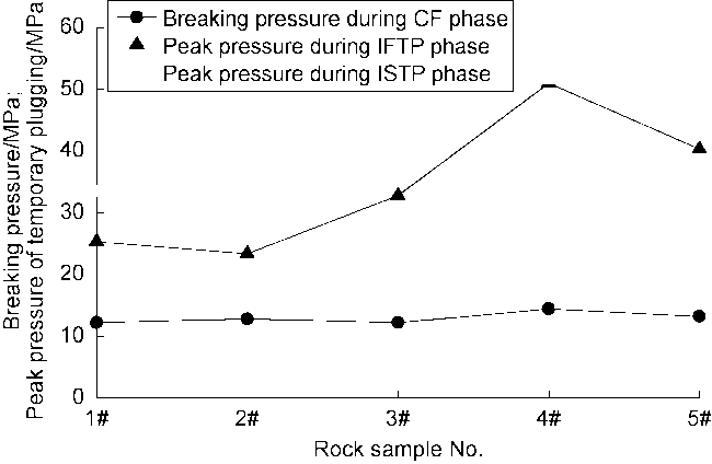
Fig. 5. Rock sample breaking pressure and peak pressure when using different particle size TPAs. |
From Figs. 5 and 6 , it can be observed that the pressure increase amplitude of 1# and 2# rock samples are similar after IFTP and ISTP adopt a single particle size TPA. Compared with the breaking pressures during CF phase, the peak pressures during IFTP phase are approximately 12 MPa higher and the peak pressures during ISTP phase are around 20 MPa higher. During the IFTP and ISTP phases, 2 to 3 new diverted fractures were generated. When using a combination of small and large particle sizes TPAs or TPAs added with fibers (samples 4# and 5#), there was a larger increase in pressure in both fractures and segments, resulting in the generation of 3 new fractures during the IFTP and ISTP phases. When employing a combination of small particle size TPAs within fractures and large particle size TPAs within segments (sample 3#), the pressure increase magnitudes were moderate with pressure increase of about 20 MPa within fractures and 30 MPa within segments, respectively. Moreover, the number of new fractures formed during the IFTP and ISTP phases is the highest, up to 6.
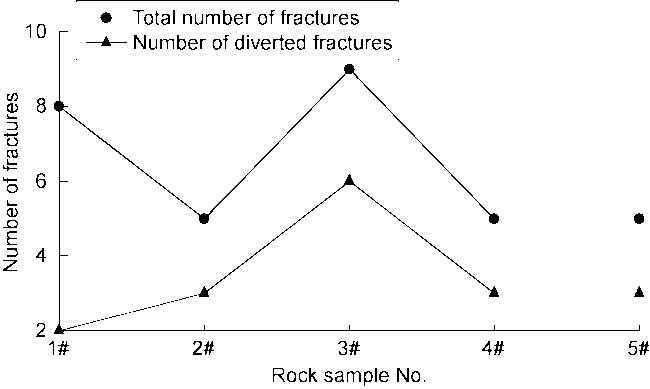
Fig. 6. Number of fractures after TPDF when using different particle size TPAs. |
Overall, the combined particle size TPAs (samples 3#, 4#, and 5#) can generate much higher peak pressures during IFTP and ISTP than single particle size TPA (samples 1# and 2#), and is more conducive to increasing plugging pressure, which is consistent with previous research results [16,21,33,51]. When using a combination of small and large particle sizes TPAs (sample 5#), the peak pressure is higher; while TPAs added with fibers (sample 4#) achieves the highest peak pressure during IFTP and ISTP phases and a faster pressure increasing process, but it exhibits poor temporary plugging effect, as fibers tend to rapidly aggregate near the perforation aperture (fracture mouth) to form a rigid plugging zone, hindering the subsequent entry of fracturing fluid and TPAs into the fractures. The combination of small particle sizes within fractures and large particle sizes within the segment (sample 3#) demonstrates moderate pressure increasing capability and better temporary plugging effectiveness.
According to the results of acoustic emission monitoring, it is evident that the 3# rock sample, treated with a combination of small particle sizes TPAs within fractures and large particle sizes TPAs within the segment, exhibited frequent acoustic emission events during both IFTP and ISTP phases, indicating a multi-stage temporary plugging and diversion (Fig. 7a ). Conversely, the 4# rock sample treated with fiber-added TPAs exhibited fewer acoustic emission events and poorer fracturing diversion effect (Fig. 7b ).
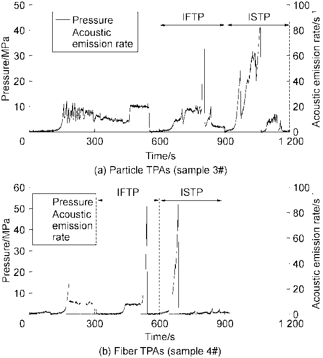
Fig. 7. Variation of pressure and acoustic emission rate over time when using different particle sizes TPAs. |
The fracture width formed by CF is approximately 1.5 mm, which is 10 times the average particle size of TPAs ranging from 125 μm to 180 μm, and 5 times that of TPAs ranging from 180 μm to 850 μm. In this scenario, the combination of the two smaller particle sizes can smoothly enter into the fractures, with the 180-850 μm TPAs forming a supportive framework and the 125-180 μm TPAs plugging the gaps within the framework, thereby creating a dense and stable plugging zone conducive to pressure buildup and fracture diversion. The perforation diameter is 4 mm, roughly 3 times the average particle size of 1-2 mm TPAs and twice that of 1-3 mm TPAs. In this context, a combination of the two larger particle sizes can enter the perforation holes without completely accumulating in the wellbore or migrating to the far end of the fracture, effectively plugging the fracture mouth and promoting diversion within the segment. Therefore, the combination of small particle sizes within fractures and large particle sizes within the segment enhances plugging pressure and facilitates multi-stage diversion of fractures.
2.2. Influences of TPA mass concentration on the propagation of multi-cluster fractures
The 6#, 7# and 8# rock samples correspond to three different TPA mass concentrations: low (40 g/L for IFTP, 20 g/L for ISTP), medium (60 g/L for IFTP, 40 g/L for ISTP), and high (80 g/L for IFTP, 60 g/L for ISTP). From Fig. 8 , it can be observed that under conditions of constant TPA particle size, single-cluster perforation number and cluster number, increasing the TPA mass concentration from low to medium significantly enhances the peak pressures during IFTP and ISTP, whereas the transition from medium to high mass concentrations results in relatively minor variations in peak pressures.
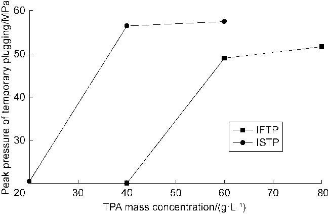
Fig. 8. Peak pressure during IFTP and ISTP phases at different TPA mass concentrations. |
From Fig. 4 and Fig. 8 , it can be observed that when using low concentration TPAs (sample 6#), the peak pressures of IFTP and ISTP reach around 20 MPa, with pressure increments less than 10 MPa. Only 2 new fractures are generated during the temporary plugging fracturing phases, and inclined longitudinal fractures with the same orientation as the NFs control the overall fracture morphology. When using medium concentration TPAs (sample 7#), the peak pressure of IFTP reaches 49.0 MPa, with pressure increment exceeding 35 MPa, while the peak pressure of ISTP reaches 56.4 MPa, with pressure increment exceeding 40 MPa, resulting in the formation of the maximum of 4 new fractures during the temporary plugging fracturing phases, with standard transverse fractures controlling the overall fracture morphology. When using high concentration TPAs (sample 8#), the peak pressures of IFTP and ISTP reach 51.6 MPa and 57.4 MPa respectively, with pressure increments close to those under medium concentration conditions. However, only 2 new fractures are generated during the temporary plugging fracturing phase, with inclined longitudinal fractures propagating along the wellbore controlled the overall fracture morphology. When using low concentration TPAs, the pressure fluctuations in the two temporary plugging phases are relatively small, and acoustic emission events are sparse (Fig. 9a ); whereas when using medium concentration TPAs, the pressure fluctuations in the two temporary plugging phases are more frequent, and acoustic emission events are dense (Fig. 9b ).
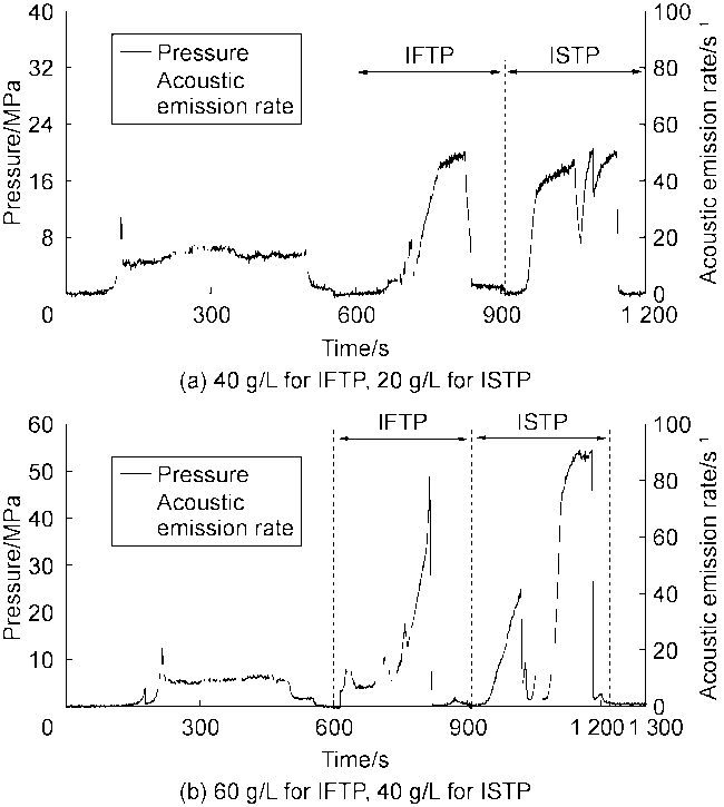
Fig. 9. Variation of pressure and acoustic emission rate over time at different TPA mass concentrations. |
Overall, the moderate concentration TPAs (60 g/L for IFTP, 40 g/L for ISTP) ensures temporary plugging for pressure buildup, leading to the generation of more diverted transverse fractures. However, increasing the concentration further does not improve the plugging and diversion effects. Under conditions where the TPA particle size, the number of perforations per cluster, and the cluster number are constant, there exists an optimal concentration of TPAs. When the concentration is below this value, the plugging zone may fail to form or remain unstable, whereas when the concentration exceeds this value, the increasing TPAs may not enter into the perforation but rather accumulate ineffectively within the wellbore.
2.3. Influence of single-cluster perforation number on the propagation of multi-cluster fractures
Samples 9#, 10# and 11# correspond to conditions with single-cluster perforation numbers of 2, 3 and 4, respectively. As depicted in Fig. 10 , significant differences in rock breaking pressure and temporary plugging peak pressure exist under different single-cluster perforation numbers. Overall, with the increase in single-cluster perforation number, the breaking pressure decreases slightly, while the peak pressure of ISTP decreases substantially.
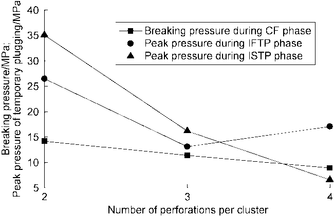
Fig. 10. Rock sample breaking pressure and peak pressure at different single-cluster perforation numbers. |
From Figs. 10 and 11 , it can be observed that when the single-cluster perforation number is 2 (sample 9#), the breaking pressure during CF and the peak pressure during ISTP are the highest, reaching 14.2 MPa and 35.1 MPa, respectively. 3 NFs and 3 transverse fractures are initiated, with 1 standard transverse fracture formed during the CF phase and 2 inclined transverse fractures generated during the temporary plugging fracturing phases, all penetrating the entire rock sample. When the single-cluster perforation number increases to 3 (sample 10#), the breaking pressure decreases to 11.4 MPa and the peak pressure during ISTP phase decreases by about 50% to 16.2 MPa. 2 beddings, 2 transverse fractures, and 1 longitudinal fracture are initiated, with 1 standard transverse fracture formed during the CF phase penetrating the entire rock sample, and 1 inclined transverse fracture generated during the temporary plugging fracturing phases propagating to the left side of the wellbore, but failing to penetrate the beddings. Continuing to increase the single-cluster perforation number to 4 (sample 11#), the breaking pressure decreases to 8.9 MPa and the peak pressure during ISTP phase decreases by over 50% to 6.6 MPa. 2 NFs, 1 transverse fracture and 1 longitudinal fracture are initiated, with only one large-angle inclined fracture formed during the CF phase, microcracks formed close to the S1 surface near the end of the inclined fracture during the temporary plugging phases, but no significant change in the fracture direction, resulting in poor temporary plugging effect. It can be seen that fewer single-cluster perforations are more conducive to increasing the breaking pressure and peak pressure during temporary plugging, and have a more significant control effect on the propagation of multi-cluster fractures.
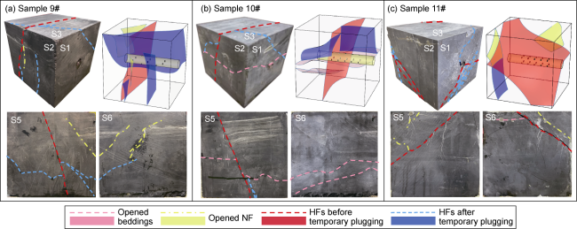
Fig. 11. Fracture morphology of rock samples after TPDF at different single-cluster perforation numbers (S5 is directly opposite S2, and S6 is directly opposite S1). |
2.4. Influence of cluster number on the propagation of multi-cluster fractures
Samples 12#, 7# and 13# correspond to cluster numbers of 3, 5 and 7, respectively. As shown in Figs. 12 and 13 , when the cluster number is 3 (sample 12#), the peak pressures for IFTP and ISTP are 27.9 MPa and 33.3 MPa, respectively, and a total of 5 HFs are generated, including 1 transverse fracture. The overall fracture morphology is significantly influenced by NFs, predominantly exhibiting longitudinal fractures. With an increase in the cluster number to 5 (sample 7#), the peak pressures for IFTP and ISTP sharply rise to 49.0 MPa and 56.4 MPa, respectively, and a maximum of 7 HFs are generated, predominantly characterized by 3 transverse fractures. Further increasing the cluster number to 7 (sample 13#), the peak pressures for IFTP and ISTP do not rise but decrease to 24.7 MPa and 42.6 MPa, respectively, and a total of 6 HFs are generated, including 1 transverse fracture. The overall fracture morphology resembles that of the 3-cluster scenario, predominantly exhibiting longitudinal fractures. When the cluster number is 5, there are more transverse fractures, resulting in more complex overall fracture morphology and a better temporary plugging effect. Fewer clusters lead to a limited number of initiated fractures during the CF phase, thereby affecting the total number and complexity of fractures. Conversely, a higher cluster number makes it difficult to effectively initiate all perforation clusters under the same displacement or achieve effective plugging during temporary plugging fracturing under equivalent TPA parameters.
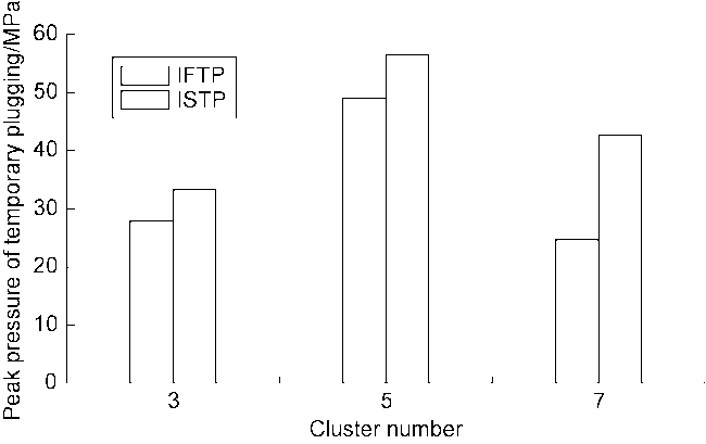
Fig. 12. Comparison of peak pressures of temporary plugging at different cluster numbers. |
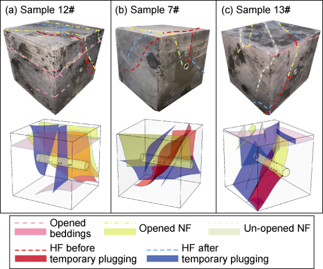
Fig. 13. Fracture morphology of rock samples after TPDF at different cluster number. |
3. Distribution of TPAs under multi-cluster perforation conditions
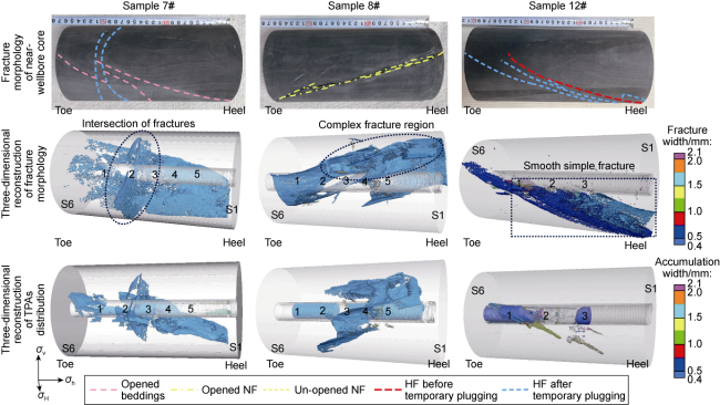
To further investigate the HF formation patterns of TPDF under multi-cluster perforation, typical rock samples 7#, 8#, and 12# were selected. Cylindrical rock samples with a diameter of 12 cm and a height of 26 cm were drilled with the wellbore as the center. Three-dimensional CT scans of near-wellbore fracture morphology and TPA distribution were conducted, as shown in Fig. 14. The laboratory experiments were conducted at a much smaller scale compared with field conditions. Due to constraints imposed by the wellbore and fracture dimensions, the experiments demonstrated superior plugging effects compared with field observations, which showed that the TPAs for IFTP were easily distributed widely within the fracture, and the TPAs for ISTP tended to accumulate in the wellbore near the perforation hole. Specifically, during the IFTP phase, fine-grained TPAs primarily entered the fractures through the initiated perforation holes and were concentrated at the intersections of fractures. During the ISTP phase, coarse-grained TPAs exhibited a preference for distribution near the perforation cluster holes corresponding to complex fracture regions near the wellbore, and additionally tended to accumulate at the toe of the wellbore.
Fig. 14. Three-dimensional CT scan results of near-wellbore fracture morphology and TPAs distribution (the numbers on the wellbore represent the perforation cluster serial number). |
The fracture plugging situations were analyzed based on fracture morphology and TPAs distribution. It was found that in sample 7#, the volume of distributed TPAs reached 10.1 cm3, forming a complex network of intersecting HFs near the concentrated distribution area; in sample 8#, the volume of distributed TPAs reached 10.3 cm3, forming a complex network of HFs near the S1 surface of the wellbore; while in sample 12#, the volume of distributed TPAs was only 1.3 cm3, with 3 longitudinal fractures propagating in parallel, exhibiting a single morphology. Overall, the larger distributed volume of TPAs (samples 7# and 8#) indicates effective migration of the TPAs into the fractures, thereby achieving a higher probability of plugging; whereas the smaller distributed volume (sample 12#) suggests ineffective migration of the TPAs into the fractures, resulting in a lower probability of effective plugging. On the other hand, the intricate intersecting pre-existing HFs (samples 7# and 8#) provide more favorable plugging positions for the TPAs, leading to fracture diversion to form a more complex HF network; whereas in samples with simpler pre-existing fractures and smoother fracture surfaces (sample 12#), the TPA tends to migrate towards the rock surface, making it difficult to form a stable plugging zone to promote fracture diversion.
Through observation of the accumulation trends of TPAs inside the wellbore, the plugging conditions within the segment were analyzed as follows: In sample 7#, TPAs were sparsely distributed near the toe, plugging all opened perforations of the second cluster and the opened perforations in the right side of the first cluster. In sample 8#, TPAs were heavily accumulated inside the wellbore, plugging all perforations. In sample 12#, TPAs were widely distributed at the toe of the wellbore, with a smaller amount distributed in the middle of the wellbore, plugging the opened perforations of the first cluster and the third cluster. Overall, the distribution of TPAs near initiated perforation clusters indicates effective plugging, while heavy accumulation near unopened perforation clusters indicates ineffective plugging. Additionally, in the case with fewer clusters (sample 12#), even if all perforation clusters are opened, the amount of TPAs entering the fractures is limited. Under laboratory conditions, simply increasing the concentration of TPAs (medium concentration in sample 7#, high concentration in sample 8#) did not significantly increase the amount of TPAs entering the fractures; excess TPAs only accumulated inside the wellbore, leading to ineffective plugging.
4. Conclusions
The peak pressures of both IFTP and ISTP phases are higher than the breaking pressure of CF phase, and their variations show consistency. The frequent and significant fluctuations in pressure during the plugging phases are the response of complex fractures, accompanied by dense acoustic emission events.
Using a combination of small particle size TPAs for IFTP and large particle size TPAs for ISTP is more conducive to increasing the plugging pressure, promoting the multi-stage diversion of HFs, and achieving better plugging effects. Adding fibers to granular TPAs can rapidly increase the pressure to ultra-high levels, but the effect of plugging the HFs is poor. When the concentration of TPAs increases to a certain value, the maximum plugging peak pressure can be reached, but further increasing the concentration of TPAs does not significantly increase the plugging peak pressure. Under conditions where the particle size of TPAs, the number of perforations per cluster, and the number of clusters are constant, there exists an optimal TPAs concentration that matches these parameters. The breaking pressure and plugging peak pressure decrease with an increase in the number of perforations per cluster. A lower number of perforations per cluster are more conducive to increasing the breaking pressure and plugging peak pressure, especially in controlling the propagation of multi-cluster fractures. A lower number of clusters hinder the increase in the total number and complexity of artificial fractures, while a higher number of clusters make effective plugging difficult to achieve.
The transport of TPAs within fractures is a complex process that significantly influences the effectiveness of plugging. TPAs within fractures are primarily distributed in the complex fracture areas where fractures intersect, while those within the segment are preferentially distributed near the perforation with multiple clusters corresponding to the complex fracture areas near the wellbore. To more accurately describe the distribution patterns of TPAs, it is necessary to further explore visualization methods.
Nomenclature
E°—elastic modulus of plane strain, Pa;
K°—corrected fracture toughness, Pa·m1/2;
L—half-length of the fracture, m;
Q—pumping displacement, m3/s;
Rmax—characteristic radius of fracture propagation, m;
S—cluster spacing, m;
tmax—characteristic time of fracture propagation, s;
X, Y, Z—Cartesian coordinate system, m;
α, β—similarity coefficient;
μ—viscosity of fracturing fluid, mPa·s;
σh—minimum horizontal principal stress, MPa;
σH—maximum horizontal principal stress, MPa;
σv—vertical stress, MPa.
Subscripts:
l—laboratory parameters;
f—field parameters.