

Introduction
In the late development stage of oil and gas fields, it is necessary to improve oil and gas recovery or exploit remaining reserves by drilling infill wells or sidetracking wells. However, these techniques may expose drilling and completion operations to abnormal reservoir pressure system, wellbore collapse, lost circulation, pipe sticking and other risks [1-2]. With the innovation and development of drilling and completion technology, the operation limits of well drilling and completion such as deep (water), unconventional hydrocarbon, and other complex petroleum formations have been continuously broken through globally. Downhole complexities or accidents (e.g. leakage, blowout, wellbore collapse, sticking, blockage, etc.) of oil and gas wells in complex formations (e.g. salt layer, high- temperature and high-pressure formation, tar/asphalt layer, shale, broken-soft coal seam, etc.) increase the risks and costs of drilling and completion engineering, and especially wellbore instability may cause huge economic loss [3⇓-5]. Managed pressure drilling technology can improve the wellbore stability in complex formations, but may be prone to the problems such as blockage and sticking during completion string running, which would result in operation failure [4,6].
With the development of liner drilling and steering drilling technologies, directional casing drilling and liner steering drilling technologies have been applied to directional and horizontal well drilling [3,7]. These technologies can enhance the wellbore stability in complex formations, prevent lost circulation, reduce reservoir damage, shorten the drilling cycle [8⇓⇓-11], and mitigate the risk of pipe sticking [12⇓-14]. The application of steerable drilling liner (SDL) in horizontal wells reduces the risk of extended reach well drilling in complex formations and increases the drilling extension limit [2,5,15]. SDL integrates a number of advanced technologies such as liner drilling, rotary steering, special downhole motor, and special bit for casing drilling [16-17], which can effectively reduce the risks in downhole operations and shorten the drilling cycle [1,4⇓ -6], but the core technologies are only mastered by a few of international oilfield service companies. The casing drilling technology transfers torque and axial force to the bottom hole assembly (BHA) and bit through the casing strings, and the liner drilling technology transmits torque and axial force to the BHA and bit through drill pipe and liner. The upper drill pipe of SDL drives the lower liner and its internal drill pipe to rotate synchronously at low speed and transmit the WOB. SDL relies on a special downhole motor to provide rotary torque for the BHA and bit, which improves the steering ability, rate of penetration (ROP) and drilling depth. However, the load of rotary equipment increases significantly, and the use and maintenance of special equipments such as rotary steering device and special downhole motor are very costly.
Based on the previous researches on the liner steering drilling technology of horizontal well, a new method of liner differential rotation drilling with double tubular strings (dual-string liner differential rotary drilling for short) of horizontal well is proposed, and the supporting tools are designed. Two rotary systems are used to drive the differential rotation of the dual-string structure in the whole wellbore to reduce the load of the single rotary system. A tool face control technique of steering drilling assembly is proposed for dual-string liner differential rotary drilling, and it can be equipped with conventional positive displacement motor (PDM) and measurement while drilling (MWD) tools for steering drilling. The extension limit prediction model is established for liner differential rotary drilling with double tubular strings of horizontal well. This technique is compared with conventional liner drilling technique for horizontal extension. The findings provide valuable references for the integrated design and control of liner completion and drilling of horizontal wells.
1. Liner differential rotary drilling with double tubular strings in horizontal well
A new method of liner differential rotary drilling with double tubular strings in the horizontal well is proposed. Rotary speed of the outer string and the inner string is adjusted by the top drive system and rotary table respectively to realize a dual-string differential rotary drilling in the wellbore. The low-speed rotation of the outer liner reduces the axial friction of tubular string, and the high- speed rotation of the inner drill pipe drives bit to break rock. The conventional MWD and PDM are equipped for steering drilling of liner differential rotary drilling with double tubular strings, thus getting rid of the dependence on rotary steering system and special downhole motor, which integrate liner completion and drilling of horizontal well.
1.1. Principles
The dual-string liner differential rotary drilling assembly for deep horizontal wells is shown in Fig. 1a . The lower drilling assembly is a dual-string structure composed of outer liner and inner small-size drill pipe. The upper drilling assembly is a dual-string structure composed of intermediate casing and inner large-size drill pipe. The lower drill pipe is connected with the upper large-size drill pipe through the thread of sliding sleeve sub inside the hanger. The lower liner is connected with the upper large-size drill pipe through the hanger and the thread at central shaft of differential rotation transmission device. The upper large-size drill pipe bears the axial load of the lower dual-string structure. The intermediate casing and the liner are connected by the key slot of differential rotation transmission device for torque transmission. The top drive and rotary table drive the rotation of the large-size drill pipe and intermediate casing, respectively. The intermediate casing rotates to reduce the axial friction in the curved section and drive the casing reaming bit to rotate and break rock. The inner drill pipes rotate at high speed to drive the pilot bit and liner reaming bit to rotate and break rock. The liner rotates at low speed to reduce the axial friction of horizontal drilling string. The liner reaming bit is connected with the small-size drill pipe through the reaming bit drive device to reduce anti-torque and vibration on the liner. The pilot bit is connected with the conventional geo-steering assembly, and the composite rotary steering device (CRSD) is installed between the conventional geo-steering assembly and small-size drill pipe to adjust and control the PDM tool face for liner differential rotary steering drilling with double tubular strings in horizontal well. Upon drilling to the designed depth, the metal ball is put into the drill pipe and pumped to the ball seat of sliding sleeve sub. The pin is cut off by hydraulic pressure, and the sliding sleeve is driven to the designed position. The hanger suspension and separation of small-size drill pipe and liner are completed, and then the large-size drill pipe and small-size drill pipe are pulled out of hole. The cementing tool is run via drill pipe into the hanger for cementing. Then, the operation string is pulled out. If the liner is a screen pipe, the cementing operation is omitted. The dual-string liner differential rotary drilling assembly for horizontal wells in medium-shallow formations is shown in Fig. 1b .
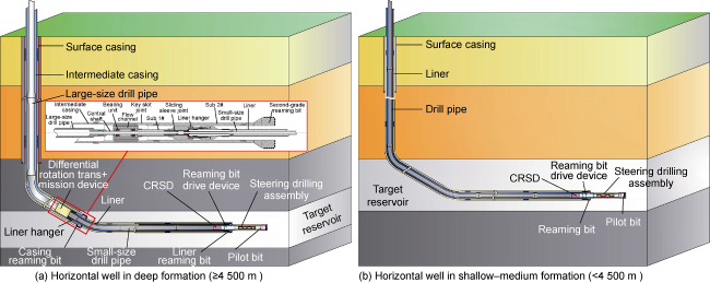
Fig. 1. Schematic diagram of the dual-string liner differential rotary drilling system for horizontal well. |
Compared with the conventional casing and liner drilling system, the dual-string liner differential rotary drilling system of horizontal well has the following features. (1) Two rotary systems are adopted to drive the dual-string structure to rotate at differential speed, enabling the operations of intermediate casing drilling and liner drilling/completion in one trip. (2) The torque transmission efficiency of rotary systems to the steering drilling assembly is improved, avoiding the excessive load of the single rotary system. (3) Compared with the rotary geo-steering system, this system controls the PDM tool face by using the CRSD, and is equipped with conventional geo-steering tools to collect the formation information and steering drilling. (4) By virtue of the optimized design of the dual-string structure, the large-size drill pipe bears the axial load of liner and small-size drill pipe, and the differential rotation of inner and outer strings reduces the friction torque of downhole string and increases the mechanical extension limit of horizontal drilling.
1.2. Key processes
Taking the dual-string liner differential rotary drilling of horizontal well in deep formations as an example, the key process is as follows: (1) The dual-string structure is connected and temporarily fixed on rotary table, as shown in Fig. 2a . If the designed liner length exceeds current well depth, the bit with the same size as the casing reaming bit is used to drill to the depth as liner length. Then, the drill string is pulled out. Next, the dual-string structure is assembled and run into the wellbore. (2) Top drive and rotary table are used to provide torque for the large-size drill pipe and immediate casing respectively. The high-speed rotation of the small-size drill pipe and the low-speed rotation of liner are controlled by adjusting the rotation speeds of large-size drill pipe and immediate casing. The small-size drill pipe drives the pilot bit to drill a small-size wellbore, as shown in Fig. 2b . (3) The low-speed rotation of the liner reduces the axial friction, and the reaming bit drive device at the front end of small-size drill pipe drives the liner reaming bit to rotate at high speed and break rock. The wellbore trajectory is controlled by the CRSD, and thus the dual-string differential rotary steering drilling is realized, as shown in Fig. 2c . (4) The rotary table drives the intermediate casing and the casing reaming bit to rotate and break rock. The drilling fluid flows through the annulus between intermediate casing and large-size drill pipe to the casing reaming bit, as shown in Fig. 2d . (5) Intermediate casing and liner drilling operations are synchronously completed. The inner and outer string separation and hanger suspension are completed through the sliding sleeve sub. Then the inner drill pipe and supporting device are pulled out of the hole. The intermediate casing is temporarily fixed on the rotary table, and the liner is hung on the inner wall of the intermediate casing, as shown in Fig. 2e . (6) The cementing sub is run to the liner hanger position through the drilling pipe, and the front end of cementing sub enters the liner hanger. When the cementing sub reaches the key slot sub of intermediate casing, the annulus is sealed under axial force. Then, the casing and liner cementing is completed, as shown in Fig. 2f . (7) The cement slurry is used to seal the outer annulus of casing and liner, and then pull out the cementing operation string. A constant pressure is holding in the wellbore for the cement slurry to solidify, as shown in Fig. 2g . (8) The PDM and PDC (polycrystalline diamond compact) bit are run into hole to grind the cement plug in the completion string. After wellbore cleaning, the drill string is pulled out hole, as shown in Fig. 2h .
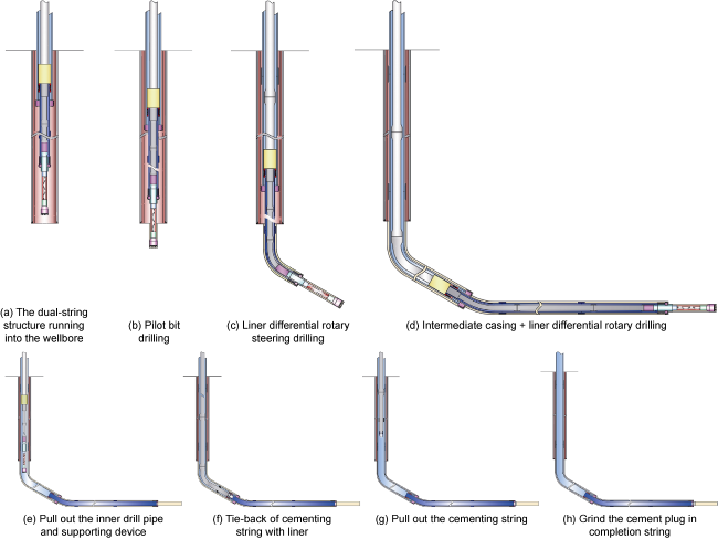
Fig. 2. Key processes of liner differential rotary drilling with double tubular strings of horizontal well. |
When it is necessary to replace the pilot bit or liner reaming bit, pull out the liner and small-size drill pipe and retain the intermediate casing in wellbore, so that the adverse effects of excitation pressure and suction on wellbore stability in complex formations during tripping can be reduced. If the casing reaming bit has to be replaced, pull out the large-size drill pipe, differential rotation transmission device and intermediate casing, and fix the liner and small-size drill pipe temporarily at the wellhead. After the casing reaming bit is replaced, Step (1) is repeated to connect the dual-string structure and run it into the hole. In addition, drilling horizontal wells in shallow-medium formation is only based on the liner with double strings. The liner string extends to the surface, while the liner cementing can be implemented directly without cementing string. If screen pipe is used for completion in the target reservoir, the staged cementing is used to seal the annulus between well wall and liner in the upper non-reservoir sections.
2. Dual-string differential rotary steering drilling assembly and tool face control method for horizontal well
The bottom steering drilling assembly of liner differential rotary drilling system is sliding during steering drilling in horizontal well, and the liner and its inner small-size drill pipe keeps differential rotation. Based on the working principles of CRSD and PDM, the rotary friction-induced nonlinear vibration occurs between the built-in friction pairs of the CRSD, and the torsional vibration occurs in PDM rotor-bit system. The CRSD-PDM system generates torsional vibration under the combined excitation of friction torque and anti-torque. By adjusting the rotation speed of inner drill pipe, the tool face of the rotary steering drilling assembly can be controlled to ensure the dual-string differential rotary steering drilling of horizontal well.
The special rotary tool can control the sectional rotation of downhole string and extend the casing running length in extended reach well [18]. Top drive rocking drag reduction system reduces the axial friction of drill string during the sliding directional drilling of horizontal well and increases the WOB, but it is difficult to fundamentally reduce the friction of long drill string and improve the ROP in long horizontal section [19-20]. The torque generated by a special device offsets the anti-torque of PDM, so as to stabilize the PDM tool face [21-22]. Based on the previous research results, the design of CRSD was optimized to incorporate double built-in friction pairs and spline hydraulic clutch to increase the friction torque. In this way, two operation modes, i.e. sliding drilling of bottom steering drilling assembly and composite rotary drilling of upper string, are realized, so as to reduce the length of bottom steering assembly and the wear of built-in friction pairs, and increase the stable operation time of CRSD.
2.1. Structure and principle of CRSD
CSRD is the key device to control the composite or steering drilling of the inner drill string. The upper joint is connected with inner drill pipe, and the lower joint is connected with the reaming bit drive device. As shown in Fig. 3a , it is not necessary to control the PDM tool face during the composite rotary drilling, and the 2# channel is closed at normal pump pressure. The drilling fluid in the inner drill pipe flows through the central pipe, 1# channel, central shaft and lower joint to reaming bit driving device. The CSRD is regarded as a rigid transmission device with the spline coupling. The torque and WOB of the inner drill pipe are transmitted to the reaming bit drive device, steering drilling assembly and bit, so that the composite rotary drilling of drill pipe and PDM is realized. PDM tool face should be controlled to keep the sliding drilling of the bottom steering drilling assembly (Fig. 3b ). The pump pressure is increased to the first level, and the hydraulic pressure pushes the first-stage sliding sleeve down to close 1# channel. The pump pressure is further increased to the second level, and the hydraulic pressure drives the second-stage sliding sleeve down to open 2# channel. The drilling fluid in the inner drill pipe flows through the central pipe, 2# channel, central shaft and lower joint to the reaming bit drive device. The inner drill pipe drives the upper joint, central pipe, shell, positioning block, thrust spring, thrust rod, external friction parts and thrust device to rotate with spline decoupling. The anti-torque of bottom steering drilling assembly is balanced by the rotational friction torque of built-in friction pairs to control the PDM tool face.
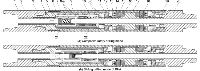
Fig. 3. Schematic structure of CRSD. 1—Upper joint; 2—Central pipe; 3—Self-aligning roller bearing; 4—Transmission shaft; 5—Spline; 6—First-stage sliding sleeve; 7—First-stage spring; 8-a—Activity piece of the second-stage sliding sleeve; 8-b—Fixed part of the second-stage sliding sleeve; 9—Shell; 10—Spring; 11—Positioning block; 12—Thrust spring; 13—Part A of the thrust rod; 14—Part B of the thrust rod; 15—External friction part; 16—Internal friction part; 17—Fixed seat of internal friction part; 18—Central shaft; 19—Thrust device; 20—Lower joint; 21—1# channel; 22—2# channel. |
CRSD has main characteristics as follows: (1) It is equipped with conventional MWD and PDM for liner differential rotary drilling with double tubular strings in horizontal well, with the engineering costs reduced. (2) The torque generated by the rotary friction of two built-in friction pairs is used to balance the anti-torque of the bottom steering drilling assembly, which reduces the length of bottom steering drilling assembly and make it applicable to dual-string differential rotary steering drilling. (3) The CRSD only works in the dual-string differential rotary steering drilling, which increases the stable operation time and provides guarantee for drilling and completion in one trip.
2.2. Tool face control of steering drilling assembly
CRSD-PDM is forced to vibrate under the combined excitation between drill bit anti-torque and CRSD rotary friction torque. The PDM vibrates under the action of bit anti-torque and stick-slip vibration, and the vibration is transmitted to the internal friction part of built-in friction pairs of CRSD. The external friction part of CRSD vibrates under the action of the upper drill string torque and stick-slip vibration. There are normal pressure and relative rotation between the internal and external friction parts, allowing the friction pairs to generate friction torque. The rotation speed of the upper drill string and the WOB are used as the control parameters of the CRSD-PDM system to control the tool face of PDM.
In the deep No. 8 coal seam (deeper than 2 000 m) at the eastern margin of the Ordos Basin, the BHA of horizontal well adopts PDM and PDC bit. According to the formation drill ability, bit type and field practice, set the WOB as 50 kN and the rotor speed of PDM as 120 r/min. The asymptotic dynamic stable torque of the PDC bit is 1 905 kN·m. The stick-slip vibration frequency of the upper drill string connecting with CRSD is 0.1 Hz, and the peak rotation speed is 68 r/min. The normal pressure between friction pairs of CRSD is 60 kN. The time step is 10 μs. The clockwise rotation direction of top drive and rotary table is defined as positive, and the counterclockwise rotation direction is defined as negative. As shown in Fig. 4a , the angular velocity of the PDM tool face shows attenuation vibration within 0.1 s, and decays from 2.527 7 rad/s to stable vibration in the neighborhood of zero point within 0.020 5 s. As shown in Fig. 4b , the PDM tool face reverses from 0 rad to attenuation vibration. After 0.020 2 s, the angular displacement of the PDM tool face is dynamically stable in the neighborhood of −0.010 34 rad, and the amplitude is 1×10⁻⁵ rad. The well trajectory is controlled accurately within sufficient time, meeting the requirements for steering drilling.
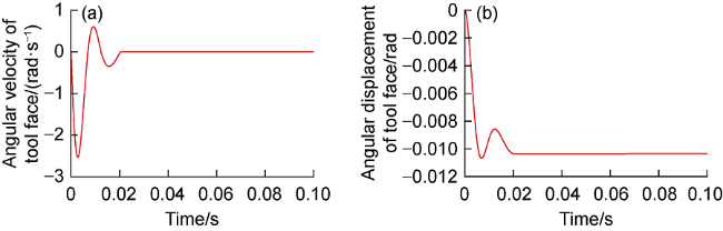
Fig. 4. Time-history response curve of angular velocity and displacement of the PDM tool face. |
The angular displacement of the PDM tool face (hereinafter referred to as the tool face angular displacement) changes with the rotation speed of the upper drill string, as shown in Fig. 5 . At the rotation speed of 70-75 r/min, the PDM rotates negatively at a small angle after the instantaneous vibration, and the angular displacement of the tool face is asymptotically stable in the range of −0.010 rad to −0.013 rad, which represents the smallest change of tool face and corresponds to the optimal rotation speed range of string. When the rotation speed of the upper drill string is 80 r/min, the PDM rotates negatively after instantaneous vibration, and the tool face angular displacement continues to increase in reverse. When the rotation speed is 65 r/min, the PDM rotates positively at a small angle, and the tool face angular displacement continues to increase slowly. When the rotation speed is 40-55 r/min, the positive growth rate of the tool face angular displacement continues to increase as the rotation speed decreases. The results show that, given the positive pressure of the built-in friction pairs of CRSD and WOB, there is an optimal drill string rotation speed range for the tool face control of the dual-string differential rotary steering drilling assembly.
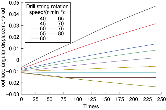
Fig. 5. Variation of the angular displacement of the PDM tool face with the upper drill string rotation speed. |
3. Extension limit of liner differential rotary drilling with double tubular strings in horizontal well
The large-scale factory operation of horizontal wells has gradually become an efficient development mode of unconventional and offshore oil and gas. The extension of horizontal and extended reach wells is one of the key technologies to reduce costs and increase efficiency in engineering practices. Based on the actual drilling engineering cases, Allen et al. proposed the drilling limit extension process [23]. Mason et al. studied the extension limit of extended reach wells through data statistics and analysis [24]. Bakke et al. adopted the data statistics method to study the drilling extension limit, and analyzed the distribution law of horizontal extension limit under different vertical depths [25]. Vestavik et al. proposed the technique of double-wall drill pipe, which increased the drilling extension limit in complex formations [26]. Wang et al. calculated the hydraulic extension limit of extended reach wells [27]. Gao et al. systematically proposed the concept of rotary drilling extension limit including open hole extension limit, mechanical extension limit and hydraulic extension limit [28]. Considering the additional bottom hole pressure, safe drilling fluid density window, circulating flow rate and other factors, an open hole extension limit calculation model of extended reach well was established [29⇓⇓-32]. Considering the drilling equipment, wellbore trajectory, string structure, drill string coupling and other factors, the mechanical extension limit calculation models under multiple working conditions were established [33⇓⇓-36]. Through gradual improvement of the open hole, mechanical and hydraulic extension limit calculation models of extended reach well [37⇓⇓⇓⇓⇓⇓⇓-45], the extension limit engineering design method and theoretical system for extended reach wells are constructed [46⇓⇓⇓-50].
The dual-string liner differential rotary drilling technology for horizontal well adopts rotary table and top drive as the rotary systems. Under the constraints of drilling system, borehole conditions and string strength, there is a limit depth for safe drilling (i.e., extension limit). Based on the mechanical model and hydraulic model of the downhole string, an extension limit prediction model for dual-string liner differential rotary drilling of horizontal well is established. It takes the drilling extension limit as the objective function, and the drilling system, downhole string buckling, pipe failure, hydraulic loss, wellbore cleaning and formation fracture as constraints, and considers the open hole, hydraulic and mechanical extension limits of horizontal well.
3.1. Extension limit of liner differential rotary drilling with double tubular strings in horizontal well
3.1.1. Extension limit prediction model
Based on the mechanical model and hydraulic model of downhole string, considering the factors such as drilling system load, downhole string buckling, pipe failure, hydraulic loss and wellbore cleaning, a prediction model for the extension limit of liner differential rotary drilling with double tubular strings is established. The allowable extension limit (Lmax) is the minimum of the hydraulic extension limit (Lh), open hole extension limit (Lo) and mechanical extension limit (Lm).
$\left\{ \begin{align} & {{F}_{\text{obj}}}=\underset{p\subset Y}{\mathop{max}}\,L\left( P,h,d,c \right) \\ & {{L}_{\text{max}}}=min\left\{ {{L}_{\text{h}}},{{L}_{\text{o}}},{{L}_{\text{m}}} \right\} \\ \end{align} \right.$
3.1.2. Hydraulic extension limit
According to the geological and physical properties of the target reservoir, casing or screen pipe is used as the completion string. In case of casing completion, conventional hydraulic equations are used to calculate the hydraulic parameters and circulation loss in the annulus between borehole wall and dual-string. In case of screen pipe completion, there are pre-drilled holes on the liner, the drilling fluid flows in the double annulus between the drill pipe, screen pipe and borehole wall, and there is fluid diffusion flow between the two annuluses. Therefore, a fluid flow model in double annulus is established here to calculate hydraulic parameters and circulation loss.
(1) Fluid flow model in double-annulus [51]: The annulus between borehole wall and screen pipe is defined as the outer annulus, and the annulus between drill pipe and screen pipe is defined as the inner annulus. The pressure difference between the outer annulus and the inner annulus is defined as the annulus pressure difference (∆p). As shown in Fig. 6a , the drilling fluid flows from the drill bit into the outer annulus at the bottom hole and diffuses into the inner annulus through the pre-drilled holes under the annulus pressure difference. During the diffusion process, the drilling fluid flow rate in outer annulus (Qa1) decreases, the drilling fluid flow rate in inner annulus (Qa2) increases, and the annulus pressure difference decreases. When the inner and outer annulus pressures are balanced, the drilling fluid stops diffusing. The red dotted box in Fig. 6a is defined as the diffusion-diverging area. When the inner and outer annulus pressures are balanced, the drilling fluid in two annuluses flows at a stable speed. The blue dotted box in Fig. 6a is defined as the diverging area. The drilling fluid flows from the inner annulus to the outer annulus when the drilling fluid reaches the liner hanger, which is defined as the diffusion-confluence area (red dotted box in Fig. 6b ) and opposite to the diffusion-diverging process. With the energy loss of drilling fluid passing through the pre-drilled holes ignored, according to the law of conservation of energy, the Bernoulli equation for the total flow (Qa) of double annulus is established as follows:
$\left\{ \begin{array}{*{35}{l}} \left( \frac{{{p}_{\text{la}}}}{{{\rho }_{\text{f}}}g}+\frac{{{k}_{f}}v_{\text{a}}^{2}}{2g} \right){{Q}_{\text{a}}}=\left( \frac{{{p}_{\text{la1}}}}{{{\rho }_{\text{f}}}g}+\frac{{{k}_{f}}v_{\text{a1}}^{2}}{2g} \right){{Q}_{\text{a1}}}+\left( \frac{{{p}_{\text{la2}}}}{{{\rho }_{\text{f}}}g}+\frac{{{k}_{f}}v_{\text{a2}}^{2}}{2g} \right){{Q}_{\text{a2}}} \\ {{Q}_{\text{a}}}={{Q}_{\text{a1}}}+{{Q}_{\text{a2}}} \\ {{Q}_{\text{a}}}={{Q}_{c}} \\ \Delta p(i)={{p}_{\text{la1}}}(i)-{{p}_{\text{la2}}}(i) \\ \end{array} \right.$ (1)
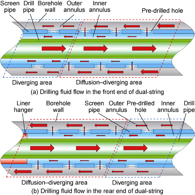
Fig. 6. Schematic diagram of drilling fluid flow in double annulus between horizontal well double strings and borehole wall [51] (red arrow denotes the direction of drilling fluid flow). |
(2) Hydraulic extension limit of dual-string: If the target reservoir is completed with casing, the outer string is casing, and the maximum circulating hydraulic loss (pmax) of the downhole dual-string is:
${{p}_{\max }}={{p}_{\text{p}}}+{{p}_{\text{ca}}}=\sum\limits_{i=1}^{N}{\left( {{L}_{i}}\frac{d{{p}_{\text{p}}}}{d{{L}_{i}}} \right)}+\sum\limits_{i=1}^{N}{\left( {{L}_{i}}\frac{d{{p}_{\text{ca}}}}{d{{L}_{i}}} \right)}$
If the target reservoir is completed with screen pipe, and the non-target reservoir is completed with casing, the screen pipe can be connected with the liner through screw thread or suspended on the inner wall of the casing. The maximum circulating hydraulic loss (pmax) of the downhole dual-string corresponding to the two string structures is:
$\left\{ \begin{align} & {{p}_{\text{max,1}}}=\sum\limits_{i=1}^{N}{\left( {{L}_{i}}\frac{d{{p}_{\text{p}}}}{d{{L}_{i}}} \right)}+\sum\limits_{i=1}^{k}{\left( {{L}_{i}}\frac{d{{p}_{\text{la1}}}}{d{{L}_{i}}} \right)+\sum\limits_{i=1}^{k}{\left( {{L}_{i}}\frac{d{{p}_{\text{la2}}}}{d{{L}_{i}}} \right)}+} \\ & \ \sum\limits_{i=k+1}^{N}{\left( {{L}_{i}}\frac{d{{p}_{\text{ca2}}}}{d{{L}_{i}}} \right)+\sum\limits_{i=k+1}^{N}{\left( {{L}_{i}}\frac{d{{p}_{\text{ca1}}}}{d{{L}_{i}}} \right)}} \\ & {{p}_{\text{max,2}}}=\sum\limits_{i=1}^{N}{\left( {{L}_{i}}\frac{d{{p}_{\text{p}}}}{d{{L}_{i}}} \right)}+\sum\limits_{i=1}^{k}{\left( {{L}_{i}}\frac{d{{p}_{\text{la1}}}}{d{{L}_{i}}} \right)+} \\ & _{_{_{\ }}}\sum\limits_{i=1}^{k}{\left( {{L}_{i}}\frac{d{{p}_{\text{la2}}}}{d{{L}_{i}}} \right)+\sum\limits_{i=k+1}^{N}{\left( {{L}_{i}}\frac{d{{p}_{\text{ca}}}}{d{{L}_{i}}} \right)}} \end{align} \right.$
The hydraulic extension limit (Lh) of dual-string drilling in horizontal well is:
${{L}_{\text{h}}}=\sum\limits_{i=1}^{N}{\left( {{L}_{i}} \right)}$
3.1.3. Open hole extension limit
Based on the calculation model of open hole extension limit in horizontal section of extended reach well [35,38], the open hole extension limit calculation model of horizontal section in dual-string drilling is improved according to the structural characteristics of dual-string liner differential rotary drilling system. The circulating pressure (pla1_h) in the outer annulus (between borehole wall and liner) and the open hole extension limit (Lo) of the liner differential rotary drilling with double tubular strings in horizontal section are:
$\left\{ \begin{align} & {{p}_{\text{la1 }\!\!\_\!\!\text{ h}}}({{Q}_{c}})={{p}_{\text{f}}}-{{p}_{\text{la1 }\!\!\_\!\!\text{ v}}}-{{p}_{\text{la1 }\!\!\_\!\!\text{ b}}}-9.81{{D}_{\text{v}}}{{\rho }_{\text{f}}} \\ & {{L}_{\text{o}}}=\frac{\max \left[ {{p}_{\text{la1 }\!\!\_\!\!\text{ h}}}({{Q}_{\text{c}}}) \right]}{\left( \frac{d{{p}_{\text{la1 }\!\!\_\!\!\text{ h}}}}{d{{L}_{\text{h}}}} \right)} \\ \end{align} \right.$
3.1.4. Mechanical extension limit
Ignoring the vibration of string, and assuming that the dual-string as a whole rotates stably in the wellbore and the rotation speed of the inner drill pipe is greater than that of the outer liner, the torque and axial force of the inner and outer string elements under differential rotating motion are calculated by the mechanical model of downhole string [52]:
$\left\{ \begin{array}{*{35}{l}} \frac{dM_{\text{T}1,{{k}_{p}}}^{{}}}{dL}=-{{\mu }_{1}}n_{\text{t}1,{{k}_{p}}}^{{}}\frac{D_{1,{{k}_{p}}}^{{}}}{2} \\ \begin{align} & \frac{dM_{\text{T}2,{{k}_{p}}}^{{}}}{dL}={{\mu }_{1}}n_{\text{t}2,{{k}_{p}}}^{{}}\frac{d_{2,{{k}_{p}}}^{{}}}{2}-{{\mu }_{2}}n_{\text{t}2,{{k}_{p}}}^{{}}\frac{D_{2,{{k}_{p}}}^{{}}}{2} \\ & \frac{dF}{dL}=-EI{{\kappa }_{\text{b}}}\frac{d{{\kappa }_{\text{b}}}}{dL}-{{q}_{\text{w}}}\cos \alpha \pm {{F}_{\text{f}}} \\ \end{align} \\ \end{array} \right.$
where “±” before Ff is taken as “+” to represent string running, and “−” to represent string pulling out.
Based on the mechanical extension limit prediction model proposed by the author, the mechanical extension limit (Lm) calculation model for dual-string drilling of horizontal well is established by considering the dual- string structure and differential rotary drilling method.
${{L}_{\text{m}}}=\sum\limits_{i=1}^{N}{{{L}_{i}}\left( P,d,c \right)}$
3.2. Case study
The production breakthrough of deep coalbed methane (CBM) wells in the eastern margin of the Ordos Basin indicates that the development of deep CBM in China has entered a new stage [53⇓⇓-56]. Taking a horizontal well in deep coal seam in the eastern margin of the Ordos Basin as an example, the extension limit calculation model proposed in this paper is used to evaluate the extension ability of the liner differential rotary drilling with double tubular stings in horizontal well. The burial depth of the target well is 1 935-1 940 m, the maximum wellbore curvature is 4°/30 m, the kick-off point is 1 455 m, and the landing point is 2 005 m. The surface casing is run to the depth of 200 m, with the upper complex formations cemented. The liner is composed of casing and screen pipe. The casing is run into the coal seam roof to 2 000 m, and the screen pipe is run into the target coal seam. The average density of coal is 1 410 kg/m3, and the average density of roof and floor rocks is 2 400 kg/m3. The drilling fluid density is 1 300 kg/m3, the flow index is 0.540 6, and the consistency factor is 0.386 1 Pa·sn. The screen pipe is pre-drilled with 20 holes per meter, with a diameter of 5 mm and regular circle shape. The rock debris formed in the drilling with PDC bit and PDM in the non-coal seam is relatively uniform and small in size (0.1-5.0 mm). The structure of coal is complex, and the debris particles of tectonic coal are not uniform in diameter [57], which ranges in 0.1-10.0 mm. The critical drilling fluid flow velocity for rock debris migration in double annulus is 0.3 m/s.
3.2.1. Open hole extension limit of dual-string drilling
The fracture pressure of deep coal in the eastern margin of the Ordos Basin is greater than that of shallow-medium coal. The fracture pressure is 46.3 MPa obtained by small-scale field fracturing test [58-59]. With the critical drilling fluid flow velocity of rock debris migration in double annulus as a constraint, the critical drilling fluid displacement of wellbore cleaning and open hole extension limit corresponding to different dual-string structures are calculated, as shown in Table 1 . The horizontal open hole extension limits of 1#-5# dual-string structures are 33 646, 20 424, 26 642, 27 084 and 27 390 m, respectively.
Table 1. Horizontal open hole extension limit of dual-string drilling |
| No. | Wellbore diameter/mm | Dual-string structure | Critical drilling fluid displacement of wellbore cleaning/(L·s−1) | Horizontal open hole extension limit/m | |
|---|---|---|---|---|---|
| Screen pipe external diameter/mm | Drill pipe external diameter/mm | ||||
| 1# | 193.7 | 139.7 | 88.9 | 10.0 | 33 646 |
| 2# | 193.7 | 139.7 | 101.6 | 22.4 | 20 424 |
| 3# | 215.9 | 177.8 | 88.9 | 34.6 | 26 642 |
| 4# | 215.9 | 177.8 | 101.6 | 26.9 | 27 084 |
| 5# | 215.9 | 177.8 | 114.3 | 19.8 | 27 390 |
3.2.2. Hydraulic extension limit of dual-string drilling
The rated pressure of the circulating system pipeline is 35 MPa; by minus the ground circulating pressure loss, the safe circulating pressure of downhole string is 30 MPa. Taking the critical drilling fluid velocity of rock debris migration in double annulus as a constraint, the critical drilling fluid displacement of wellbore cleaning and hydraulic extension limit corresponding to different string structures are calculated (Table 2 ). The horizontal hydraulic extension limits of 1#, 2# and 5# dual-string structures are 10 735, 6 245 and 1 201 m, respectively. The circulation pressure of 3# and 4# double-string structures exceeds 30 MPa under the condition of critical drilling fluid displacement for wellbore cleaning, which cannot meet the dual-string horizontal drilling. Where the stimulation and production operation requirements are satisfied, 1# and 2# dual-string structures are preferred.
Table 2. Horizontal hydraulic extension limit of dual-string drilling |
| No. | Wellbore diameter/mm | Dual-string structure | Critical drilling fluid displacement of wellbore cleaning/(L·s−1) | Horizontal hydraulic extension limit/m | |
|---|---|---|---|---|---|
| Screen pipe external diameter/mm | Drill pipe external diameter/mm | ||||
| 1# | 193.7 | 139.7 | 88.9 | 10.0 | 10 735 |
| 2# | 193.7 | 139.7 | 101.6 | 22.4 | 6 245 |
| 3# | 215.9 | 177.8 | 88.9 | 34.6 | |
| 4# | 215.9 | 177.8 | 101.6 | 26.9 | |
| 5# | 215.9 | 177.8 | 114.3 | 19.8 | 1 201 |
3.2.3. Mechanical extension limit of dual-string drilling
The mechanical forces of 1#, 2# and 5# dual-string structures are calculated, and the mechanical extension limit of dual-string drilling is obtained. There are three modes of dual-string drilling: M1, low-speed rotation of liner + sliding drilling of drill pipe; M2, synchronous low-speed rotary drilling of liner and drill pipe; M3, dual-string liner differential rotary drilling. As shown in Table 3 , the mechanical extension limits of 1# dual-string structure under three drilling modes are 1 810, 2 595 and 3 852 m, respectively, and the horizontal footage of M3 is 112.82% and 48.44% greater than that of M1 and M2, respectively. The mechanical extension limits of 2# dual- string structure under three drilling modes are 1 533, 2 411 and 3 993 m, respectively, and the horizontal footage of M3 is 160.47% and 65.62% greater than that of M1 and M2, respectively. The mechanical extension limits of 5# dual-string structure under three drilling modes are 552, 1 101 and 2 107 m, respectively, and the horizontal footage of M3 is 281.70% and 91.37% greater than that of M1 and M2, respectively. The results show that compared with M1 and M2, M3 (liner differential rotary drilling with double tubular strings) can effectively increase the mechanical extension limit of horizontal drilling.
Table 3. Horizontal mechanical extension limit of dual-string liner differential rotary drilling |
| No. | Wellbore diameter/mm | Dual-string structure | Horizontal mechanical extension limit/m | |||
|---|---|---|---|---|---|---|
| Screen pipe external diameter/mm | Drill pipe external diameter/mm | M1 | M2 | M3 | ||
| 1# | 193.7 | 139.7 | 88.9 | 1 810 | 2 595 | 3 852 |
| 2# | 193.7 | 139.7 | 101.6 | 1 533 | 2 411 | 3 993 |
| 5# | 215.9 | 177.8 | 114.3 | 552 | 1 101 | 2 107 |
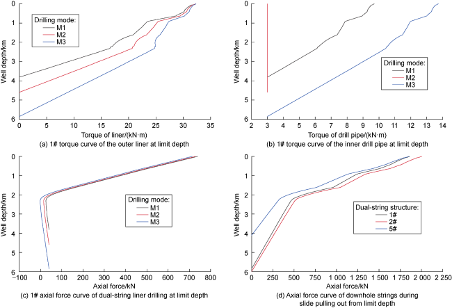
During the drilling with 1#, 2# and 5# dual-string structures, the friction torque between liner and cuttings bed and borehole wall is transmitted to the rotary table, and the friction torque between drill pipe and liner and the rock-breaking torque of drill bit are transmitted to the top drive system. Taking the 1# dual-string structure as an example, the torque of rotary table under M1, M2 and M3 modes is significantly greater than the top drive torque, as displayed in Fig. 7a and Fig. 7b . This indicates that the rated torque of rotary table is the decisive factor for the extension limit of dual-string drilling. With the rated torque of rotary table of 32.36 kN·m as the constraint, the limit depths under the three modes are 3 810, 4 595 and 5 852 m, respectively. The maximum shear yield stress of P110 casing is 438.2 MPa, the elastic limit torque of casing body is 86.5 kN·m, and the limit make up torque of thread is 92.28 kN·m [60-61]. The maximum torque (32.36 kN·m) of liner corresponding to the limit well depth under three modes is less than the elastic limit torque of casing body and the limit make up torque of thread, meeting the requirement of safe drilling. Fig. 7c shows the axial force curve of 1# dual-string drilling to the limit well depth under M1, M2 and M3. The maximum axial forces of the downhole string under the three modes are 780.87, 729.03 and 713.47 kN, respectively, which do not exceed the rated lifting load (3 150 kN) of top drive, meeting the requirement of safe dual-string drilling. Fig. 7d shows the axial forces of 1#, 2# and 5# dual-string pulling out from the limit depth. The maximum axial forces of the downhole string under the three modes are 1 861.33, 2 003.28 and 1 854.14 kN, respectively, which do not exceed the rated lifting load of top drive, meeting the requirement of safe drilling.
Fig. 7. Torque curves (a, b) and axial force curves (c, d) of dual-string structures. |
3.2.4. Extension limit of dual-string drilling
Considering the circulating pressure loss and force of the dual-string structure, the minimum of open hole, hydraulic and mechanical extension limits is taken as the extension limit of liner differential rotary drilling with double tubular strings in horizontal well. As shown in Table 4 , constrained by the mechanical extension limit, the extension limit of 1# and 2# dual-string horizontal drilling in Φ193.7 mm wellbore is 3 852 m and 3 993 m, respectively. Constrained by the hydraulic extension limit, the extension limit of 5# dual-string horizontal drilling in Φ215.9 mm wellbore is 1 201 m. If the mechanical extension limit of dual-string is the decisive factor, drilling and completion engineering should focus on reducing the friction and torque of the dual-string structure in horizontal well. If the hydraulic extension limit of the dual-string is the decisive factor, drilling and completion engineering should focus on improving the rock debris migration efficiency of the double annulus and reducing the hydraulic loss.
Table 4. Extension limit of liner differential rotary drilling with double tubular strings in horizontal well |
| No. | Wellbore diameter/mm | Dual-string structure | Lo/m | Lh/m | Lm/m | Lmax/m | |
|---|---|---|---|---|---|---|---|
| Screen pipe external diameter/mm | Drill pipe external diameter/mm | ||||||
| 1# | 193.7 | 139.7 | 88.9 | 33 646 | 10 735 | 3 852 | 3 852 |
| 2# | 193.7 | 139.7 | 101.6 | 20 424 | 6 245 | 3 993 | 3 993 |
| 5# | 215.9 | 177.8 | 114.3 | 27 390 | 1 201 | 2 107 | 1 201 |
4. Conclusions
A new method of dual-string liner differential rotary drilling of horizontal well is proposed. It is equipped with special downhole tools such as differential rotation transmission device, composite rotary steering device and hanger. The dual-string differential rotary drilling in the whole wellbore is driven by two rotary systems, which avoids the excessive load of single rotary system in conventional liner drilling processes. This technology integrates safe and efficient operation of liner completion and drilling, which reduces engineering risks and costs effectively. A composite rotary steering device is designed for the liner differential rotary drilling with double tubular strings in horizontal well. A PDM tool face control method for dual-string differential rotary steering drilling of horizontal well is proposed, which is equipped with conventional MWD and PDM.
Based on the extension limit calculation model of liner differential rotary drilling with double tubular strings, the deep CBM horizontal well in the eastern margin of the Ordos Basin is taken as an example for case study. The results show that the horizontal extension limit of 1# dual-string structure is 1 810 m and 2 595 m under low- speed rotation of liner + sliding drilling of drill pipe and synchronous low-speed rotary drilling of liner and drill pipe. Under the same conditions, the extension limit under dual-string liner differential rotary drilling is 3 852 m, which indicates a significant increase of the horizontal drilling length. The dual-string structures suitable for Φ193.7 mm and Φ215.9 mm boreholes are optimized respectively, corresponding to the decisive factors as mechanical extension limit and hydraulic extension limit respectively.
Nomenclature
c—operating conditions such as pulling out of hole and running in hole;
d—dual-string structure, wellbore trajectory, downhole tools and other design parameters;
d2—inner diameter of the outer string, m;
Dv—reservoir depth, m;
D1—inner string diameter, m;
D2—outer string diameter, m;
E—elastic modulus of string, Pa;
F—axial tension of downhole string, N;
Ff—friction per unit length of the downhole string, N/m;
Fobj—objective function of extension limit of dual-string liner differential rotary drilling in horizontal well;
g—gravity acceleration, m/s2;
h—hydraulic constraints such as drilling fluid performance, hydraulic circulating pressure and critical flow velocity of rock debris migration;
i—well section element number;
I—moment of inertia of pipe cross-section, m4;
k—number of screen pipe elements;
kf—flow coefficient, dimensionless;
L—downhole string length, m;
Lh—hydraulic extension limit of dual-string liner drilling of horizontal well, m;
Li—length of well section i, m;
Lm—mechanical extension limit of dual-string liner drilling in horizontal well, m;
Lmax—maximum extension limit of dual-string liner drilling in horizontal well, m;
Lo—open hole extension limit of dual-string liner drilling in horizontal well, m;
MT1—inner string torque, N·m;
MT2—outer string torque, N·m;
n—rheology index, dimensionless;
nt1—normal force of the inner string acting on the outer string, N;
nt2—normal force of the dual-string acting on borehole wall, N;
N—element number of completion string, and $1\le i\le k\le N$;
pca—hydraulic loss in the annulus between downhole dual- string and borehole wall in the casing completion section, Pa;
pca1, pca2—hydraulic loss in annulus of casing-borehole wall and casing-drill pipe, Pa;
pf—reservoir fracture pressure, Pa;
pla—annulus pressure between the first-grade reaming bit at the front end of screen pipe and the borehole wall, Pa;
pla1, pla2—outer and inner annulus pressure, Pa;
pla1_b—outer annular circulation pressure of the well section with large deviation (greater than 30°), Pa;
pla1_h—outer annular circulation pressure of horizontal well section, Pa;
pla1_v—outer annular circulation pressure of the well section with small deviation (less than and equal to 30°), Pa;
pmax—the maximum hydraulic loss of downhole dual-string, Pa;
pmax,1—the maximum circulating hydraulic loss of downhole dual-string with the screen pipe and liner connected by screw thread, Pa;
pmax,2—the maximum circulating hydraulic loss of the downhole dual-string with the screen pipe hanging on the inner wall of the casing, Pa;
pp—hydraulic loss of downhole string, Pa;
P—mechanical parameters such as lifting system load, rotary system load and pipe failure limit;
∆p—pressure difference between outer annulus and inner annulus, Pa;
qw—gravity of downhole string per unit length in drilling fluid, N/m;
Qa—total drilling fluid flow rate in double-annulus, L/s;
Qa1—drilling fluid flow rate in outer annulus, L/s;
Qa2—drilling fluid flow rate in inner annulus, L/s;
Qc—critical drilling fluid displacement of wellbore cleaning, L/s;
va—drilling fluid flow velocity, m/s;
va1, va2—drilling fluid flow velocity in outer and inner annulus, m/s;
Y—allowable region of the constraint parameter, that is the constraint condition;
α—deviation angle, rad;
${{\kappa }_{\text{b}}}$—borehole curvature, m−1;
μ1—friction coefficient between inner string and outer string, dimensionless;
μ2—friction coefficient between borehole wall and outer string, dimensionless;
ρf—drilling fluid density, kg/m3.
Subscript:
kp—if kp=1, the inner and outer strings are small-size drill pipe and liner, respectively; if kp=2, the inner and outer strings are large-size drill pipe and intermediate casing, respectively.