

Introduction
The global recoverable reserves of low-maturity and medium-to-high-maturity shale oil are 2 099×108 t and 413×108 t, respectively [1]. However, after finishing an over 70-year history of net oil import through continuous theoretical innovations and iterations on drilling and fracturing technologies [2⇓-4], the average shale oil production of the United States exceeded 820×104 bbl/d (1 bbl=0.159 m3), accounting for 68.9% of its total crude oil production, and the average shale gas production reached 22.12×10⁸ m3/d, accounting for 65.7% of its total natural gas production [5] in 2022. The shale revolution has transformed the global energy landscape, and played a significant role in increasing the diversity of the global energy supply and promoting energy transition and sustainable development [6].
Shale oil resources in continental rift lake basins are up to 346×108 t in China, and of which, China Petroleum and Chemical Corporation (Sinopec in brief) operates on approximately 41% of these resources [3-4,6]. With significant differences in sedimentary environments, reservoir conditions and fluid properties, the development technology of marine shale oil in the United States may not be completely suitable for developing shale oil in the continental rift lake basins in China. The marine shale in North America is characterized by stable structures, gentle formations, and relative homogeneity. However, shale in continental rift lake basins has undergone multiple intense tectonic movements and is characterized by deep burial, developed fault/fracture, low maturity, and strong heterogeneity. All these characteristics mean a lot of development difficulties. Therefore, it is urgent to develop an integrated geological, engineering, reservoir and management technology system suitable for shale oil in continental rift lake basins.
Research on the history of marine shale oil development in North America indicates that technological iteration is the inevitable path toward the commercial development of shale oil and gas. This article summarizes and analyzes the achievements in drilling, fracturing and development technology iterations for shale oil in continental rift lake basins, especially the shale oil in the Jiyang Depression, and proposes the development direction for technological iteration in shale oil development with the intent to accelerate the establishment of a series of efficient development technologies for shale oil in continental rift lake basins and provide a reference for achieving benefit development of shale oil.
1. Iteration and effects of shale oil and gas development technologies in the United States
The United States has witnessed the rapid progress of shale oil and gas development technology since 2005, and made two breakthroughs [7⇓⇓-10]: (1) The first shale revolution from 2005 to 2014. Shale gas production achieved explosive growth in the United States through the “horizontal well + hydraulic fracturing” technology, and key shale gas production areas such as Barnett, Eagle Ford, and Marcellus were put into production successively, which resulted in a continuous decline in natural gas prices. At low gas prices and high oil prices, all oil and gas operators began to explore the feasibility of using the “horizontal well + hydraulic fracturing” technology to produce shale oil. The first large-scale breakthrough was made to Bakken shale oil, and then the second in the Permian Basin. (2) The second shale revolution from 2015 to 2018. The international oil price plummeted and remained low in 2014, leading to the bankruptcy of hundreds of shale oil and gas companies in the United States. However, some companies improved drilling and completion efficiency and reduced well construction costs by technological iteration. They survived the crisis, and achieved a rapid growth in shale oil production by increasing the recoverable reserves per shale oil well from 2.0×10⁴ t to 8.0×10⁴ t [11]. The most remarkable technological iteration is on drilling and fracturing operation, which enabled the shale oil and gas companies in the United States to drill many “three-super and one-enhanced” (super long horizontal sections, super one-trip drilling, super well pad, and enhanced drilling parameters) horizontal wells, significantly improving the efficiency of shale oil and gas development.
1.1. Iterative advances in drilling technology
The iterative progress of shale oil and gas drilling technology in the United States has mainly undergone three stages: the breakthrough to cluster horizontal well drilling technology, super one-trip drilling technology, and automatic high-efficiency drilling technology.
1.1.1. Breakthrough to cluster horizontal well drilling technology
Aiming at the characteristics of cluster horizontal well drilling operations, efficient and mobile drilling rig technology and batch drilling modes for cluster horizontal wells were developed through technological breakthroughs. Additionally, industrialized operation has reduced the moving time between wellheads to 30 min. For example, 60 horizontal wells were drilled by 20 cluster horizontal well groups to develop four formations in the Permian Basin, reducing operational costs by 6% to 8% [12]. Some super well pads can accommodate up to 64 wells to develop five formations.
1.1.2. Integrated application of super one-trip drilling technology
To achieve economic development of shale oil and gas, oil and gas companies in the United States have developed a super one-trip drilling technology that integrates PDC (polycrystalline diamond compact) bit, long-life screw and rotary steerable system. The application of rotary steerable systems exceeds 90%, and it has become common to complete the buildup section and horizontal section of a horizontal well at one trip. In the Permian Basin, Eagle Ford, and Bakken shale oil, the one-trip footage reached 4 448, 5 790 and 4 000 m, respectively, significantly improving drilling efficiency and reducing drilling costs. For example, Baker Hughes only used 3.5 d to complete a 5 405 m deep horizontal shale oil well in the Denver-Julesburg Basin in the United States [13].
1.1.3. Automatic drilling technology
The introduction of automatic and intelligent systems has significantly improved drilling efficiency and safety [14], representing a trend in the drilling industry. Oil and gas companies in the United States have implemented an intelligent closed-loop drilling system composed of real- time geological parameter measurement, dual-direction information transmission between surface and downhole, and surface monitoring to realize automatic and efficient horizontal well drilling operation as well as remote control on directional drilling tools, and increased the rate of penetration (ROP) by 27.5% [15].
The iterative progress of drilling technology has laid a solid foundation for cost reduction and efficient development of shale oil in the United States [16-17]. The drilling cycle has been significantly shortened. As evidenced by Southwest Energy, the average horizontal section increased from 1 097.9 m to 1 872.1 m, and the drilling cycle reduced from 25.6 d to 9.0 d in the Appalachia block [18]. The “one-trip” drilling technology further reduced the drilling cycle to 5-10 d [19-20]. The ROP increased from 79.25 m/d in 2012 to 329.18 m/d in 2018, by 315.38% [21]. The length of the horizontal section also increased significantly, generally around 3 000 m [21-22] for shale oil wells. The well construction cost decreased from $6 800 per meter in 2012 to approximately $3 333 per meter in 2022 [23].
1.2. Iterative upgrades in fracturing technology
To increase effective stimulated reservoir volume and reduce costs, the fracturing technology for shale oil and gas in the United States has continuously evolved in dense cutting volume fracturing, enhanced sand-adding, and temporary plugging and diverting [24]. The parameters have been continuously optimized, and the technology has undergone iterative upgrades. The development of fracturing technology has undergone three iterative upgrades: staged fracturing in horizontal wells, volumetric fracturing in horizontal wells, and dense cutting volume fracturing in long horizontal wells. Each technological iteration brought significant improvements on fracturing parameters (Table 1 ).
| Fracturing parameters | Horizontal section length/m | Number of sections | Number of perforation clusters | Cluster spacing/m | Fracturing fluid/(m3•m−1) | Proppants/ (t•m−1) | Duration/ (sections•d−1) |
|---|---|---|---|---|---|---|---|
| First generation | 1 300‒1 600 | 8‒16 | 2‒4 | 15‒30 | 10‒18 | 1.0‒2.3 | 2‒4 |
| Second generation | 1 600‒1 800 | 20‒26 | 6‒9 | 10‒19 | 15‒27 | 2.0‒2.5 | 6‒8 |
| Third generation | 1 800‒4 800 | 50‒80 | 12‒15 | 3‒12 | 28‒57 | 4.0‒6.0 | 12‒18 |
1.2.1. Staged fracturing technology
The combined application of horizontal well and fracturing technology has significantly enhanced the effectiveness of shale oil and gas development, and achieved leapfrog progress. Staged fracturing technology in horizontal wells can greatly increase the contact between reservoirs and fractures, which results in a multiplicative increase in stimulation effects compared with vertical well fracturing stimulation. The first-generation fracturing technology focuses on fracturing reservoirs and creating long fractures on both wings. However, it is accompanied by a small number of stages and clusters, larger cluster spacing, lower pumping rate, and lower proppant concentration. The first-generation horizontal well fracturing technology is still in its infancy, and the key fracturing technical indicators are low.
1.2.2. Volumetric fracturing technology
Limited by reservoir conditions, well patterns, and fracturing processes, only increasing fracture length doesn’t significantly enhance shale oil and gas production. To achieve efficient development of shale oil and gas, a complex fracture system is constructed with major fractures as the primary component and branch fractures as the secondary component, and this kind of fracture system means three-dimensional stimulation to shale reservoirs. Under favorable market and policy conditions, new operation models and techniques were developed, including well pad/group, synchronous fracturing, zipper fracturing, extreme limited-entry perforation, integrated variable-viscosity fracturing fluid system, fully soluble bridge plugs, and quartz sands (replacing ceramic proppants). These achievements doubled fracturing efficiency. In addition, fracturing parameters such as horizontal section length, cluster spacing, fracturing fluid volume and proppant concentration were updated, too. As a result, the single well production was enhanced while engineering costs declined.
1.2.3. Dense cutting volume fracturing technology in long horizontal wells
Dense and short fractures are usually induced [28] to increase the stimulated reservoir volume (SRV) near wellbore. With the decrease in well spacing, fracturing process gradually evolved from “multiple stages + fewer clusters + proppant slugs” to “multiple cluster dense cutting + limited-entry fracturing + temporary plugging and diverting”. The combination of super well pads with the fracturing technology featured by large fracturing fluid volume, high proppant concentration and small cluster spacing has increased fracturing fluid volume and proppant concentration by approximately two times and reduced comprehensive sand-fluid ratio by over 10%. This significantly improved the fracturing stimulation effect and led to a great increase in shale oil and gas production [29-30]. Furthermore, quartz sands and slickwater contributed to continuous reduction in fracturing costs.
1.3. Upgrade of well pattern
As shown by machine learning results from shale oil development in the Midland subbasin of Permian Basin, the total production increase from two new wells in a parallel well pattern is only equivalent to the average production from 0.26 new wells in a staggered well pattern. Furthermore, the single well production of the staggered pattern is higher than that of the parallel pattern. The staggered well pattern was more effective [31]. The development of Wolfcamp shale oil in the Permian Delaware Basin adopted the staggered well pattern to expand the vertical distribution of SRV while reducing the overlap area of SRV between adjacent horizontal wells [32]. Field practices proved that high interference and stress shadow between wells could be observed when well spacing is less than 150 m, and both the surface area of proppants and propped fracture space are small. When well spacing is larger than 200 m, the reservoir between wells can not be fully fractured, so recovery is low. Therefore, the best horizontal well spacing is 200 m [33].
With the iteration and upgrading of well patterns, ConocoPhillips began to add infill wells in the Eagle Ford shale oil in 2013 by accepting a certain level of interference between wells. The well spacing gradually reduced from 200 m to 100 m, and the number of producing pay zones increased from two to four [34]. The technological iterations in drilling, fracturing and well patterns have reduced the shale oil cost from $110/bbl to $35/bbl in the Permian Basin (Midland) in the United States since 2011. This successful experience provides valuable insights into shale oil and gas development in China [35⇓-37].
The geological characteristics of shale oil in continental rift lake basins in China are different from those in the United States. Therefore, it is necessary to strengthen independent innovations after learning, understanding and absorbing the iterations of shale oil development technology in the United States. We will strive to establish our own iterative system of development, drilling, and fracturing technologies, enhance efficiency and reduce costs. All these efforts will steadily promote the profitable development of shale oil in continental rift lake basins in China [38].
2. Technological iterations for shale oil development in Jiyang continental rifted lake basin
2.1. Geological characteristics of Jiyang shale oil
Compared with shale oil in other basins in China and abroad, shale oil in Jiyang continental rift lake basin exhibits significant differences in terms of shale sedimentary time, environment and scale, mineral composition, thermal evolution, temperature and pressure fields, tectonic system, and fluid properties (some parameters in Table 2 ). Shale oil reservoirs in Jiyang continental rift lake basin are characterized by low evolution degree, deep burial, large thicknesses, high temperatures and pressures, complex structures, complex lithofacies, and complex fluid properties. Specifically, it is organic-rich shale developed in the Cenozoic Paleogene, so it is relatively new with low thermal evolution extent. The resources with Ro (reflectance of organic matter) less than 0.9% account for 90%. The burial depth ranges from 3 000 m to 5 500 m, and the thickness varies from 300 m to 600 m, locally up to 1 500 m [39].
Table 2. Comparison of Jiyang shale oil with North American shale oil |
| Origin | Sedimentary facies | Lithology | Burial depth | Ro/% | Crude oil density/(g•cm−3) | Pressure coefficient | Viscosity/ (mPa•s) | GOR/ (m3•m−3) |
|---|---|---|---|---|---|---|---|---|
| Jiyang Depression | Lacustrine facies | Muddy limestone, limy mudstone | 3 000‒5 500 | 0.5‒1.0 | 0.82‒0.94 | 1.20‒2.00 | 16.80 | 40‒1 300 |
| Permian Basin | Marine facies | Sandstone, muddy limestone | 2 200‒3 000 | 0.6‒1.5 | 0.82 | 1.50 | <1.00 | 40‒1 600 |
| Bakken Formation in Williston Basin | Silty and fine sandstone, felsic shale | 2 100‒3 300 | 0.7‒1.3 | 0.82 | 1.20‒1.60 | 0.45 | 89‒249 | |
| Eagle ford shale in the Gulf Coast Basin | Muddy limestone | 1 000‒3 400 | 0.5‒2.0 | 0.84 | 1.30‒1.80 | <1.10 | 240 |
The Upper Submember of the 4th Member of the Econe Shahejie Formation (Es4U) and the Lower Submember of the 3rd Member of the Econe Shahejie Formation (Es4L) in the Jiyang Depression were deposited in a semi-deep to deep lacustrine environment, an overall saline environment. The results in a high content of carbonate minerals in the shale (ranging from 11.0% to 95.0%, with an average of 48.6%). Under the effect of hydrocarbon generation and pressure increase in the primary shale formations, the formation pressure coefficient reaches 1.2 to 2.0 and the formation temperature reaches 130 °C to 200 °C, forming an abnormally high-pressure and high-temperature system. The complexity of Jiyang shale oil is mainly reflected in three aspects: lithofacies, structures, and fluid properties. There are up to 16 types of shale oil lithofacies. In them, laminated muddy limestone and laminated limy mudstone are the most widely distributed ones, and characterized by high limestone content, well-developed high-frequency laminated structures, and high organic matter abundance. Multi-stage and high-intensity tectonic movements promoted the development of faults and structural fractures at various levels. Affected by thermal evolution and burial depth, the fluid properties of Jiyang shale oil are diverse. The crude oil density ranges from 0.82 g/cm3 to 0.94 g/cm3. Medium oil is dominant, and light oil is found locally. Simultaneously, the fluid properties vary rapidly in both horizontal and vertical directions, and there are significant differences in crude oil properties at different sags and depths [40]. Therefore, the development of Jiyang shale oil cannot directly copy the technologies used for North American shale oil and gas. Through continuous innovation and practice, we should establish shale oil development technologies that are suitable for the geological characteristics in China.
2.2. Development technology
The development of shale oil is characterized by high initial production capacity, rapid production decline, and significant challenges in maintaining stable production. Based on the geological features and fluid properties of shale oil in the Jiyang Depression, key technologies have gradually been developed through development practices, including sweet spot evaluation, well pattern optimization, and well spacing design.
2.2.1. Precise sweet spot evaluation is the foundation of beneficial development
The technology of precise sweet spot evaluation is the foundation for achieving beneficial development of shale oil. The evaluation on sweet spots of shale oil in the Jiyang continental rift lake basin has primarily experienced two stages: the “four-property” favorable lithology evaluation during the early exploration stage and the geological-engineering “dual sweet spot” evaluation during the development pilot stage [41].
Rock physics experiments on cores and logging curves (DEN, CN and AC) were used to estimate the “four kinds of properties” of shale reservoirs (reservoir physical properties, oil-bearing property, fluid mobility, and fracturability) during the early exploration stage, and a multi-mineral volume model was established for Jiyang shale oil reservoirs. Based on multiple logging response equations, the volume fractions of various mineral components and fluids, as well as the content of brittle minerals were calculated. Fitting logging curves, multi-mineral inversion, and other methods were used to quantitatively evaluate reservoir porosity and permeability. Geochemical parameters like TOC (total organic carbon content) and Ro (reflectance of organic matter) were calculated through fitting logging curves, curve overlay, and other methods.
During the pilot stage, focus was on evaluating the geological-engineering “dual sweet spots” on the limestone-rich shale oil reservoirs in gentle slope zones and the mixed shale oil reservoirs in steep slope and deep subsag zones. The favorable lithofacies of limestone-rich shale oil reservoirs in gentle slope zones are laminated sparry muddy limestones and cryptocrystalline limy mudstones. The favorable lithofacies of mixed shale oil reservoirs in steep slopes and deep subsag zones are laminated mixed shales. Guided by the theory of shale oil enrichment in continental rift lake basins, and based on systematic cores, core experiments, well logging and mud logging data, a systematic analysis was conducted on the differences in geological and engineering parameters of various layers to clarify the vertical sweet spot distribution in different wells. The core, testing and logging data were comprehensively analyzed, and the differences in key parameters, such as maturity, porosity, brittle minerals, and pressure coefficients in different locations, were clarified for horizontal prediction of sweet spots. Considering the important factors influencing the generation and enrichment of shale oil, geological quality evaluation parameters such as TOC, Ro, porosity, and the total thickness of favorable lithofacies that cover hydrocarbon source rocks, reservoirs, and oil-bearing properties, and engineering quality parameters such as brittleness index, rock mechanics, and interlayer thickness, quantitative evaluation criteria for shale oil sweet spots (Table 3 ) were constructed. Compared with limestone-rich shale in gentle slope zones, mixed shale in steep slope and deep sag zones has higher maturity and more developed fractures. After sweet spots were selected, fracturing simulations were conducted to analyze the height, length, and stimulated reservoir volume at different target positions to find the most favorable target window location and guide multi-layer well deployment. For example, the quantitative evaluation criteria of shale oil sweet spots were utilized in NY1-3HF horizontal well deployment in the Niuzhuang Sag. The actual drilling length of the horizontal well was 2 425 m, and the drill-in ratio of Category I sweet spots was 100%. 78 649 m³ of fracturing fluid and 4 667.2 m³ of proppants were injected. The well had worked for 644 d by April 6, 2024, and produced cumulative oil of 3.59×10⁴ t. It’s a good production result.
Table 3. Geological-engineering dual-sweet spot evaluation criteria for shale oil in the Jiyang Depression |
| Sweet Spots | Geological factors | Engineering factors | ||||||
|---|---|---|---|---|---|---|---|---|
| Ro/% | Pressure coefficient | Favorable lithofacies percentage/% | Favorable lithofacies thicknesses/m | Brittle mineral content/% | Elastic modulus/GPa | Poisson's ratio | Interbed/barrier thicknesses/m | |
| I | 0.7‒1.0 | >1.4 | >60 | >30 | >60 | >20 | <0.3 | <3 |
| II | 0.6‒0.7 | >1.4 | 30‒60 | >30 | >50 | 15‒20 | 0.3‒0.4 | <5 |
| III | 0.6‒0.7 | 1.2‒1.4 | 10‒30 | 10‒30 | >50 | <15 | >0.4 | >5 |
2.2.2. Optimizing well pattern to increase the control on shale oil reserves
Using horizontal wells to develop shale oil in the Jiyang Depression is still in a test phase. The well location plan underwent two stages: single-layer development and multi-layer three-dimensional development. The FYP-1 well group adopted single-layer development to avoid pressure channeling and reduce interference between wells, with a well spacing of 380-500 m and a horizontal section length of 2 000 m. Then, to increase the reserves controlled by well group, a multi-layer three-dimensional staggered well pattern was used for the test well group in the Niuye 1 Block, with a well spacing of 300-410 m and a horizontal section length of 2 000-3 000 m.
To explore the best horizontal well pattern for shale oil, after making a breakthrough to single well production, a planar single-layer pilot was conducted on the FYP-1 well group in the Boxing Sag, the Jiyang Depression. Fracturing parameters and fracture monitoring results of multiple fractured wells were analyzed, and the relationship between fracturing scale and fluid volume injected into a section was established. It is found that the fracture half-length first increased and then became gradually stable as more fracturing fluid was injected, and then the increase in the fracture half-length slowed down when it exceeded 200 m, indicating that the fracture propagation ability was limited to a certain extent. By referring to the shale oil and gas development practices in North America, the horizontal well spacing was designed to be twice the fracture half-length monitored by microseismic survey. Simulation results (Fig. 1 ) indicate that a well spacing of 400 m to 450 m is the best spacing that can ensure high producing inter-well reserves and suppress pressure interference.
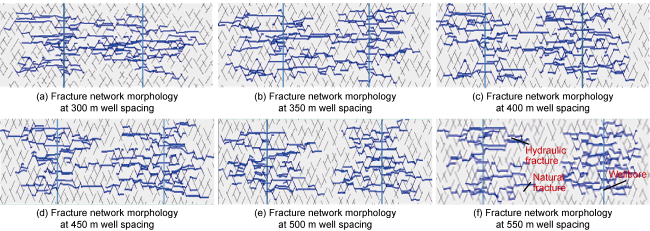
Fig. 1. Simulation results of fracture network morphology at different well spacings. |
The faults and fractures of different scales were comprehensively considered in the FYP-1 well group, the first pilot well group where the fault system is complex. Then, five horizontal wells were deployed in the C5 layer, and the well spacings were 380, 450 and 500 m. The rationality of well spacing was tested by monitoring the interference between wells during fracturing operations. Microseismic and tracer monitoring indicated that the inter-well fracture intersection was not prominent, and the interference was mainly due to pressure transmission, with a relatively small proportion of fluid channeling interference caused by natural fractures. At 2.7 m3/m to 3.2 m3/m of proppants and 45.5 m3/m to 52.0 m3/m of fracturing fluid, the average fracture length was 329 m, indicating some zones were not fractured among the wells. The result demonstrated that a well spacing of 380 m to 500 m was too large under the current fracturing parameters. As there are differences between the model parameters (natural fracture density, distribution, etc.) and the actual geological conditions, and the influence of well interference on fracture propagation was not fully considered, the practical results were not completely consistent with the simulation results. In the future, it is necessary to refine the geological model and improve the simulation method for fracture propagation.
Based on the successful development of multiple horizontal wells in a single pay zone, considering the large vertical thickness and multiple favorable lithofacies, a multi-layer development experiment was carried out in the Niuzhuang Sag to explore how to control more reserves of shale oil. Fracturing physical simulation, numerical simulation, and fracture monitoring have shown that major fractures extended vertically to the maximum height at the perforation point, and fracture height rapidly decreased at places away from the perforation point. It is comprehensively believed that the fracture morphology perpendicular to the horizontal wellbore exhibits a “rhombic” shape. Based on the geological characteristics and production performance in the study area, two well patterns were designed through fracture simulation and reservoir numerical simulation: a direct well pattern and a staggered well pattern (Fig. 2 ). The results indicate that the staggered well pattern has a long stable production period and high cumulative oil production because of higher producing reserves among wells. The direct well pattern exhibits stronger interferences among wells in different rows, resulting in lower producing reserves, a shorter stable production period and lower cumulative oil production than the staggered well pattern.
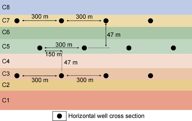
Fig. 2. Schematic diagram of a staggered well pattern for shale oil development in Jiyang Depression (C1-C8 are sublayer SNs). |
A certain degree of fracturing impact and pressure interference exists among wells, but this does not necessarily indicate well-to-well interference during oil well production. Based on the microseismic monitoring, production performance, reservoir numerical simulation, and reservoir engineering method related to NY1-3HF in the Niuzhuang Sag, the produced reserve was calculated after fracturing. The results indicate that there are three flow regions during horizontal well development, namely, an easy flow zone, a slow flow zone, and a stagnant flow zone. In the early stage of production, oil and gas mainly originated from the artificial fracture network, when flow resistance is low, and production is high, but production quickly declines. This region is defined as an “easy flow zone”. The pressure within the artificial fracture network gradually declines as development progresses, and the matrix begins to supply oil to the network. However, the fluid supply speed is slow due to the extremely low matrix permeability, and this region is defined as a “slow flow zone”. The total oil production contribution from the easy flow zone and the slow flow zone accounts for approximately 98%. The outer radius of the slow flow zone approaches to the limit drainage radius, which can be determined through transient production analysis based on early production data from producing wells. The zone where shale oil doesn’t flow is referred to as a “stagnant flow zone”. Fracturing simulation results indicate that, the frequency of pressure channeling is 64% to 83% when well spacing ranges from 200 m to 300 m, indicating severe pressure channeling. The existence of a stagnant flow zone between two wells can prevent pressure channeling but results in less producing reserve. They may decrease by 9 to 21 percentage points when the stagnant flow zone is between 30 m and 80 m. The well spacing should match with the artificial well pattern and the artificial fracture network when producing multiple layers at the same time. The goal of “connecting but not channeling” was achieved by optimizing well pattern, spacing and fracturing parameters when developing Fuling shale gas. Field data statistics show that fracturing 252 new wells caused 408 interferences to old wells, of which 84% are positive impact, and 2% are negative impact on the old wells in the primary well pattern, and the last 14% no impact [42].
If the slow flow zones between wells overlap, the goal of “connecting but not channeling” can be achieved. This is the key to the optimization of the well spacing for Jiyang shale oil. Field statistics indicate that the limit drainage radius for matrix shale is 155 m, 180 m for laminated shale, and 205 m for naturally fractured shale. Under current fracturing conditions, comprehensive optimization can determine reasonable parameters such as well spacing and layer spacing for different shales, as shown in Table 4 .
Table 4. Reasonable well spacing and layer spacing for different shales |
| Shale types | Well spacing/m | Layer spacing/m | Recoverable reserves per well/104 t |
|---|---|---|---|
| Matrix | 300‒310 | 50‒65 | 4.2 |
| Laminated | 300‒360 | 45‒55 | 5.0 |
| Naturally fractured | 350‒410 | 65‒85 | 6.5 |
2.3. Iteration of drilling technology
The development of drilling technology for shale oil horizontal wells in the Jiyang Depression has gone three stages: technical exploration, innovative research, and integrated enhancement. An optimal and fast drilling technology system has been established, which is centered on “three-section well structure + synthetic drilling fluid + precise pressure control + temperature resistant rotary steerable system + ground cooling”. It has updated the shale oil drilling goal from “achievable drilling” to “fast drilling” and then to “excellent drilling” (Table 5 ).
Table 5. Iterative process of drilling technology for Jiyang shale oil |
| Iterative stages | Time | Iterative direction | Measures | Results |
|---|---|---|---|---|
| Technological exploration | 2011-2020 | Optimization of well structure | Three-section well structure; selected bit and casing series; optimization of wellbore trajectory | Achievable drilling |
| Innovative breakthrough | 2021‒2022 | Enhancement of drilling fluid system | Composite salt drilling fluid; synthetic drilling fluid; rotary steerable system + LWD | Fast drilling |
| Integration and enhancement | 2023 to present | Development of high-end tools and equipment | Precise pressure control; temperature resistant rotary steerable system + cooling equipment; discharge/pumping parameters; and high-end automatic equipment | Excellent drilling |
2.3.1. Optimizing well structure for achievable drilling
Most target shale oil reservoirs are distributed in Es3L and Es4 in the Jiyang Depression. The pressure in and above the middle submember of the 3rd Member of the Eocene Shahejie Formation (Es3M) is normal, and the bearing capacity has an equivalent density of 1.5-1.6 g/cm³. The pressure gradually increases from Es3L, and reaches a coefficient of 1.8 to 2.0 in Es4U. Under such conditions, it’s inevitable to encounter upper leakage and lower well kick scenarios if both high and low pressure systems are opened in the same open-hole section. To ensure successful drilling, a technical casing must be installed in the horizontal section when the drilling fluid density is over 1.6 g/cm³, and the installing depth shall exceed the low-pressure layers in and above Es3M. This can prevent simultaneous occurrence of well kick and leakage when drilling the third section. Based on the selected three-section well structure, a well-adapted well structure series were established by comprehensively considering the well construction cycle and the need for fracturing stimulation and optimizing the bit and casing series (Table 6 ).
Table 6. Comparison of the first-generation and the second-generation well structures |
| Drilling technology iteration | Well structures | Application effects | Representative wells |
|---|---|---|---|
| First-generation | Φ339.7 mm+Φ244.5 mm (blocking Es3U)+Φ139.7 mm | The formation leaked at the casing shoe after the drilling fluid density of the third section reached 1.7 g/cm³ | NY1-1HF |
| Second- generation | Φ339.7 mm+Φ244.5 mm (blocking Es3M)+Φ139.7 mm | The final drilling density was 1.80-1.95 g/cm3, with no leakage detected through the upper casing shoe | FY 1-1HF and NY1-2HF |
Take the Minfeng Sag as an example. The formation pressure curve in the target block was established based on logging data, fracturing pressure experiments, and actual drilling data. The mechanical equilibrium to avoid well kick, lost circulation, collapse and stuck pipe in the open- hole section was analyzed. The technical casing was calculated to be set at approximately 3 150 m and the well could be completed in Es3M by using a bottom-up well structure design method. The final well structure is:
The first spud section is Φ444.5 mm×Φ339.7 mm, at a vertical depth of 400 m. The second spud section is Φ311.2 mm×Φ244.5 mm, at a vertical depth of 3 150 m. The third spud section is Φ215.9 mm×Φ139.7 mm, and the cement returned to the wellhead.
In early drilling operation, the Φ311.2 mm borehole in the second section encountered challenges such as difficult direction with PDC bits, low ROP, and a short service life of roller cone bits, so that a well would be finished only after three to four trips. After optimizing well trajectory and bit, a well in the pilot group in the Niuye 1 Block could be finished by two-trip in the second spud section. After taking a series of measures on the bit, screw and hydro-oscillator, drilling parameters, well trajectory, and high-performance drilling equipment, a well in the pilot group in the Minfeng Sag could be finished by one-trip in the second spud section. Multiple rounds of technological iteration and improvements have helped reduce trips in the second spud section with large boreholes of directional wells with three-section structures, and initially, a one-trip drilling technology was established in the second spud section.
2.3.2. Enhancing drilling fluid system for “fast drilling”
The focus was shifted to improving drilling efficiency after “achievable drilling”. Severe hydration and mud- making may easily make drilling tools packed, stuck and jammed, and it is difficult to control rheological properties in the upper shale oil reservoirs in Jiyang continental rift lake basin. These issues may result in excessively thick mud cakes and poor borehole cleaning. Additionally, there are risks of high-viscosity oil invasion and wellbore collapse when drilling at high temperature and high pressure. Conventional water-based drilling fluid systems cannot meet the requirements of drilling horizontal shale oil wells.
Innovative approaches were employed, including the utilization of Ca2+ and Na+ to reduce water activity and increase osmotic pressure. Additionally, K+ was used to limit swelling and separation to ensure strong inhibition properties of drilling fluid while keeping the borehole clean. This approach is effective in reducing short trips and gauge reaming, resulting in more regular wellbores and higher cementing quality. According to the reservoir characteristics, mud-making capacity, formation water type and activity, over 200 sets of inhibition and rheological evaluation experiments were conducted. By considering rock-carrying effects, the inhibition properties of drilling fluid were enhanced through synergistic application of macromolecular polymers, amine-based polyols, and inorganic salts. These optimization efforts have promoted to establish water-based drilling fluid systems suitable for different blocks (Table 7 ).
Table 7. Performances of different drilling fluid systems |
| Drilling fluid | Formula | Specific performance and indicators | Effects |
|---|---|---|---|
| Water-based drilling fluid | 1%‒3% Bentonite slurry + 0.5%‒2% CaCl2 + 5%‒10% NaCl + 2%‒5% KCl + 1%‒2% Fluid Loss control agent + 2%‒5% Lubricant + 0.5%‒1.0% Rheology modifier + 2%‒3% Graded filler | Density: 1.05‒1.15 g/cm³; Viscosity: 30‒35 s; Plastic viscosity: 8‒15 mPa·s; Yield point: 1‒3 Pa; Gel strength: 0‒2 Pa or 4‒6 Pa; pH: 8; Radioactivity: less than or equal‒0.9 Bq | Mechanical ROP during the second spud section increased by over 80%. |
| Low-solid synthetic drilling fluid | 80% Synthetic base fluid + 20% CaCl2 Aqueous solution + 3%‒4% Complex emulsifier + 1%‒3% Wetting agent + 3%‒5% Alkalinity adjuster + 0.5%‒1.0% Organic clay + 1%‒2% Fluid loss control agent | Base mud specifications: Oil-water ratio: 80:20; Plastic viscosity: 10‒20 mPa·s; Dynamic shear stress: 2‒4 Pa; Gel strength: 1‒2 Pa or 2‒4 Pa; Demulsification voltage: 350‒550 V; Density: 1.85 g/cm³ Wellbore mud specifications: Plastic viscosity: less than or equal 40 mPa·s; Dynamic shear stress: greater than or equal 8 Pa; Gel strength: 3‒5 Pa or 6‒10 Pa | Discharge rate increased from 30 L/s to 35‒ 37 L/s |
In early drilling operations, diesel-based drilling fluid induced several problems, such as low flash point, high volatility, significant harm to human health, large drilling fluid loss, poor resistance to high-pour-point oil contamination, and difficulty in controlling rheological properties. In addition, suction often led to hard well control and wellbore instability during tripping. To cope with these challenges, a low-relative-molecular-weight synthetic base was developed. This base fluid composed of low-carbon hydrocarbons is featured by a highly branched structure of isoparaffins. It boasts of a high ignition point, a low pour point, environmental friendliness, low viscosity, excellent low-temperature fluidity and high-temperature stability. To tackle the problems of high-temperature and high-pour-point oil invasion and poor wellbore stability, a low-clay-content synthetic drilling fluid system was formulated using the base fluid. It can increase displacement and ROP and keep borehole clean. This system is further enhanced with high-temperature-resistant emulsifiers, dispersive viscosity reducers, and multi-scale sealing agents (Table 7 ). The system can work at high temperature up to 230 °C, severe crude oil invasion up to 20%, and high formation pressure up to 7 MPa. As a result, wellbore stability and drilling safety are highly enhanced, which shortens the drilling cycle of the third spud section by 35%. However, compared with foreign technologies, the low-viscosity synthetic drilling fluid requires further testing.
2.3.3. Developing high-end tools and equipment for “excellent drilling”
2.3.3.1. Precise pressure control drilling equipment
To improve pressure control in deep and ultra-deep shale oil wells, the SL-Balance series of the first-generation electro-hydraulic precise pressure control drilling system and the second-generation electric precise pressure control drilling system were developed (Table 8 ). The second-generation electric precise pressure control drilling unit has improved technical indicators such as wellhead pressure control accuracy, equipment size and weight, and choke valve opening and closing time. This equipment achieves high responsiveness, high precision, and other performance metrics, representing a significant technological upgrade. It can successfully address the challenges of simultaneous well kick and leakage when drilling shale oil wells, accelerating the pace of shale oil exploration and development.
Table 8. Comparison of parameters of precise pressure control drilling equipment for shale oil in the Jiyang Depression |
| Drilling system | Drive type | Pressure level/ MPa | Pressure error/ MPa | Equipment volumes/ m3 | Equipment weight/t | Numbers of pipelines | Pipeline size/ mm | Choke size/ mm | Execution accuracy/ mm | Opening/ closing time/s | API standard |
|---|---|---|---|---|---|---|---|---|---|---|---|
| Electro-hydraulic precise pressure control | Electro- hydraulic control drive | 35 | ±0.25 | 36.50 | 13 | 4 | 103 | 65 | 0.50‒1.00 | 20 | API Spec 6A |
| Fully electric precise pressure control | Integrated electric linear drive | 35 | ±0.10 | 11.97 | 6 | 4 | 103 | 80 | 0.03 | 7 | API Spec 6A, 16C |
Under the influences of high temperature and pressure, reservoir sensitivity to pressure, and narrow safe pressure window, it is highly prone to wellbore leakage, overflow, and even oil displacement when drilling in Jiyang shale oil reservoirs. In addition, oil invasion may significantly impact the performance of synthetic drilling fluid. To this end, the second-generation fully electric pressure control drilling system was adopted under the principles of “micro overbalance, micro flow rate, and micro leakage”. The whole process involves drilling, stand connecting, tripping, casing running and cementing under pressure control. Drilling operation starts with the lower limit of drilling fluid density window at casing pressure of 0 to 2 MPa applied at wellhead. Backpressure is adjusted real time based on overflow and leakage. As of April 6, 2024, this technology has been applied in nearly 30 wells. Leakage and overflow were suppressed, drilling fluid loss was reduced by 54% and the drilling and completion cycle was shortened by 67.6%.
2.3.3.2. Supporting equipment for drilling long horizontal sections
The super one-trip drilling technology in the United States provided new insights for the iteration of horizontal well drilling technology for Jiyang shale oil. Jiyang shale oil reservoirs are characterized by high temperature, high pressure, and fracture development, so that they are prone to malfunctioning the rotary steerable drilling system and concurrent well kick and leakage. In the NY1 area, the application of air-cooling and water-cooling equipment reduced the circulation temperature by an average of 10 °C to 15 °C, ensuring that the rotary steerable system could operate continuously at 125 °C to 135 °C. Therefore, irreversible damage to drilling tools caused by high temperatures is reduced. Ground cooling equipment was not used in Well NY1-3-301HF, resulting in circulation temperature up to 164 °C. However, it was used in Well NY1-3-501, resulting in circulation temperature 120 °C to 125 °C, demonstrating the effectiveness of the cooling technology. This technology provides reliable support for achieving optimal and fast drilling in the horizontal sections in the NY1 area and for subsequent efficient development of Shengli shale oil.
The development and application of precise pressure control drilling equipment and supporting devices for drilling long horizontal sections have significantly improved the capability of controlling horizontal well trajectory in Jiyang shale oil reservoirs. The twenty wells in the pilot well group in the NY1 area were drilled by five batches. The drill-in rate of favorable lithofacies increased from 94% in the first round to over 99%. All completed trajectories met the design specifications.
Through the iteration of drilling technology, an optimal and fast drilling technology system was formed for Jiyang shale oil, which is centered on a three-section well structure, synthetic drilling fluid, precise pressure control, high-temperature-resistant rotary steering system, and ground cooling. The initial average drilling cycle of the pilot well group in the NY1 area was 80.0 d. After continuous learning and optimization, and three rounds of technology iteration, the average drilling cycle reduced to 34.3 d (Fig. 3 ) by a reduction of 57.1%. With further technological iterations, the drilling cycle in the Niuzhuang Sag and the Minfeng Sag reduced to less than 30.0 d. full rotary steerable drilling was implemented in the third spud section of 11 wells, and nine wells were completed in one trip, with the shortest cycle of 10.0 d. The “1+1+1” mode (three one-trip drilling in three spud sections) was implemented in the Minfeng Sag for the first time. The shortest drilling cycle is 24.5 d by a reduction of 28.6%. By optimizing the three-section well structure, drilling breakthroughs have been made in several subsags. Well depth exceeded 6 000 m, and the horizontal section increased from less than 2 000 m to 3 300 m by an increase of over 65%.
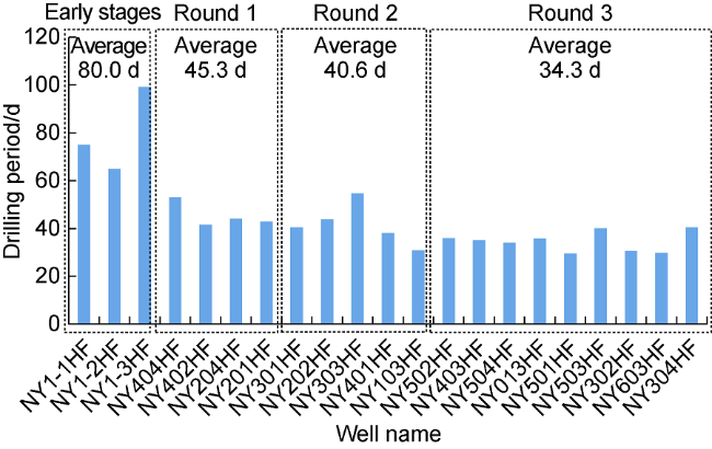
Fig. 3. Change of drilling circle of pilot well group in NY1 area. |
2.4. Fracturing technology iteration
Through enhanced research on fracturing technologies in Jiyang shale oil development, we have achieved a significant qualitative leap in shale oil fracturing technologies, which evolved from the first-generation horizontal well + fracture network fracturing technology, to the second-generation horizontal well + dense cutting volume fracturing technology, and ultimately to the third-generation horizontal well + extremely limited entry close-spaced volume fracturing technology (Table 9 ). This evolution has brought about a leap forward in fracturing process, and promoted the transition from achievable fracturing, to fast fracturing, and to excellent fracturing (Table 10 ). It represents three rounds of technology iteration, ranging from fracture network fracturing, close- spaced volume fracturing, to extremely limited entry dense cutting volume fracturing.
Table 9. Iterative process of fracturing technology for Jiyang shale oil |
| Generation | Period | Fracturing technology | Technology series | Facility | Field application | Result |
|---|---|---|---|---|---|---|
| First- generation | 2018‒ 2020 | Fracture network fracturing + horizontal well | Reducing breakdown pressure by pre- set acidizing wormhole; energizing and promoting fracture and enlargement by CO2, multi-stage fracturing, high- conductivity fracturing | 2000-type diesel-driven equipment | Production capacity breakthrough in YYP 1 and FYP 1 wells | Achievable fracturing |
| Second- generation | 2021‒ 2022 | Dense cutting volume fracturing + horizontal well | Multi-size, fully-supported, dense cutting volume fracturing, balanced expansion; multi-well, coordinated fracturing | 5000-type fully electric-driven equipment | Successful implementation in NY1 experimental well group | Fast fracturing |
| Third- generation | 2023 to present | Extremely limited entry dense cutting volume fracturing + horizontal well | Extremely limited entry + tip temporary blocking; non-uniform perforation | Electric-driven automatic equipment | Smooth progressing on large platforms and small well groups in Minfeng Sag | Excellent fracturing |
Table 10. Iteration of fracturing parameters for Jiyang shale oil |
| Generation | Horizontal section length/m | Fracturing section length/m | Cluster spacing/m | Sand-adding intensity/(t•m−1) | Comprehensive sand ratio/% | Stimulated reservoir volume per stage/ 104 m3 |
|---|---|---|---|---|---|---|
| First-generation | <1 500 | 75 | 20‒30 | 1.2 | 4 | 20‒35 |
| Second-generation | 1 500‒3 500 | 60‒70 | 10‒20 | 3.8 | 6 | 40‒50 |
| Third-generation | 3 000‒4 800 | 50‒60 | 3‒8 | 4.5 | 9 | 50‒70 |
Currently, the fracturing parameters for Jiyang shale oil are generally similar to those of the third-generation fracturing technology used in North American shale oil development, especially in terms of fractured section length, cluster spacing, pumping rate, fracture fluid volume, and sand-adding intensity. However, with large differences in shale oil depth, horizontal stress, and the development of natural fractures, improvements are still required to fill gaps in parameters such as horizontal section length, fracture density, and the volume of slickwater used.
2.4.1. Breakthrough in single-well productivity made by fracture network fracturing technology
Jiyang shale oil reservoirs are generally over 3 500 m deep, and characterized by poor physical properties, complex lithology and strong plasticity, so it is difficult to fracture. In early exploration and development, conventional volume fracturing operation failed to inject fracturing fluid at a scale of 10 000 cubic meters and proppants at a scale of 1 000 cubic meters. The flow conductivity of the induced fracture network was insufficient to meet the requirement of economical and efficient production. For example, the shale oil production from Well B1H dropped from a peak of 8.22 t/d to less than 1.00 t/d within one month after fracturing, and challenges in difficult fracturing, insufficient support, small SRV, and low productivity were outstanding.
To cope with challenges in poor physical properties and difficult fracturing, a new high-conductivity fracture network fracturing technology featured by CO2+acid, variable viscosity fracturing fluid, and pulse adding sand to major fractures to reduce fracturing pressure and promote fracture propagation was developed for the shale oil reservoirs in the Jiyang Depression.
A complex fracturing fluid injection mode was proposed, which is featured by using CO2 and acid to reduce fracturing pressure and promote fracture propagation, and injecting low-viscosity fracturing fluid, followed by high-viscosity fracturing fluid. Laboratory experiments have shown that supercritical CO2 soaking can reduce the shale fracturing strength by 9% to 20%. Field fracturing practices have demonstrated that the reservoir breakdown pressure could be reduced by 19 MPa after injecting 200 t of CO2 and 30 m³ of low-viscosity acid fluid. Simulation of fracture propagation by CO2-energized fracturing revealed that the density of the fracture network increased from 0.06 fractures/m to 0.13 fractures/m when the proportion of pre-injected CO2 increased from 10% to 30%, representing a 117% increase. CO2 is effective to improve fracturing stimulation. Pre-injecting CO2 fracturing technology has been applied in 69 horizontal wells in shale oil reservoirs.
A combination of emulsion-type thickener and synergists was employed to enhance the viscoelasticity and temperature resistance of fracturing fluid for achieving intermolecular self-assembly and interpenetration. This process allows the attraction between anions and cations to form ionic bonds, facilitating viscosity enhancement. The composite fluid exhibits excellent temperature and shear resistance even at a low dosage. The fracturing fluid formulated with a 1.2% mass fraction composite fluid, maintained a viscosity greater than 40 mPa·s when tested at 160 °C and a shear rate of 170 s−¹ for 2 h. Additionally, this fracturing fluid possesses a superior sand-carrying capacity. The proppant settlement rate is only 3.6×10⁻⁴ mm/s over 24 h, as evidenced by static sand-carrying experiment.
In terms of proppants, considering a complex fracture network system consisting of self-supporting fractures, branch fractures and major fractures, a study on fracture conductivity simulation revealed that using quartz sands with equal particles ranging from 0.212-0.380 mm (40-70 mesh) + 0.150-0.212 mm (70-120 mesh) + 0.109-0.150 mm (100-140 mesh) instead of 0.109-0.212 mm (70-140 mesh) can enhance the migration and effective support of proppants in branch fractures, and induce staggered filling in remote self-supporting fractures. Quartz sands replaced ceramic proppants entirely in Well NY1-2HF. Specifically, 0.109-0.150 mm (100-140 mesh) quartz sands were used to reduce filtration and pressure, and modify fracture morphology. 0.150-0.212 mm (70-120 mesh) quartz sand supported the major fractures, while 0.212-0.380 mm (40-70 mesh) quartz sand supported the fracture mouth and near-wellbore fractures. This approach improved the placement height and supporting distance of proppants, resulting in an increase of over 30% in the effective support volume of the branch fracture network. This operation achieved multi-level support for induced fractures. Stimulated by the fracture network fracturing technology and producing through an 8 mm choke, the oil production from Well FYP1 was at most 171 t/d during the production test.
2.4.2. Increasing SRV through dense cutting volume fracturing
With the deepening of shale oil exploration and development in the Jiyang Depression, some early problems were found, such as excessively large fracture spacing and inadequate produced reserves among fractures. In the early stages, the fracture spacings were generally larger than 50 m, resulting in low “fracture-controlled reserves”, and not very effective fracture propagation through most perforation clusters, and consequently poorer fracture complexity and less produced reserves between fractures. According to the characteristics of the shale oil reservoirs in the Jiyang Depression, a dynamic propagation model for multiple fractures by dense cutting volume fracturing in horizontal wells was established using the finite element method. Numerical simulation was conducted to study the effects of induced stress difference, net pressure, and fracture width on interference between fractures. Key fracturing parameters were optimized, including but not limited to the number of perforation clusters per section, cluster spacing, and fracturing operation scale, which formed a dense cutting volume fracturing parameters chart (Fig. 4 ). Based on the simulation method for hydraulic fractures in bedding-rich shale, the cluster spacing was reduced from the initial tens of meters to 8-12 m, and the number of perforation clusters per section was increased from the original 2-3 clusters to 5-9 clusters, in order to minimize the negative impact of stress interference and maximize stimulated reservoir volume. It is also considered balanced stimulation for bedding-rich shale layers.
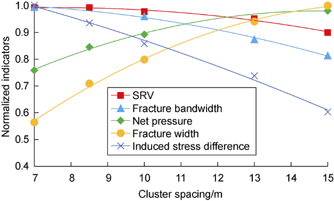
Fig. 4. Dense cutting volume fracturing parameters chart for horizontal wells in shale oil reservoirs. |
The temporary plugging and diverting technology was used to improve the uniformity of reservoir stimulation by addressing the severe non-uniform propagation of multiple clusters of fractures. Field practices showed that without temporary plugging, the propagation of the middle clusters of fractures was limited, resulting in inadequate stimulation. After implementing temporary plugging, fracture propagation was relatively balanced, and the drainage area of the fractured zone increased (Fig. 5 ). Rope knots and flexible plugging agents were used in the Jiyang Depression. The plugging pressure could be over 11 MPa. The “dense cutting volume fracturing + temporary plugging” technology changes fracturing process from “fracturing reservoir” to “crushing reservoir”, and increases SRV from 1 312×104 m3 to 1 710×104 m3 in a well.
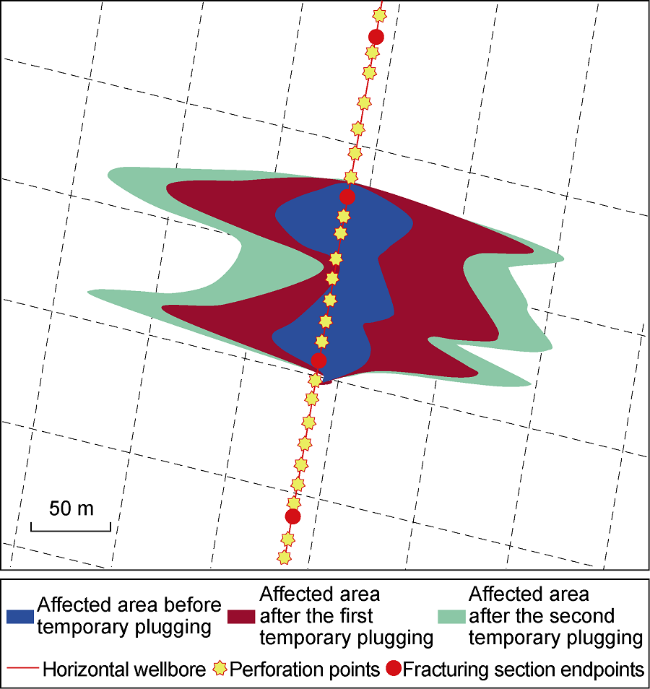
Fig. 5. Fracture shapes before and after temporary plugging and diverting. |
2.4.3. Maximizing fracture-controlled reserves through extremely limited entry dense cutting volume fracturing
By fully utilizing the stress field induced by fractures, the reserves in the zones between clusters that have not been sufficiently stimulated could be effectively produced, and consequently increasing well-controlled reserves and recoverable reserves. Simulation to stress interference between fractures at different cluster spacings indicates that a small cluster spacing may cause high stress inter-ference. The fractures would expand unevenly due to the stress interference when the cluster spacing is less than 5 m (without initiation in the middle part or limited fracture length), while the stress interference is relatively low when the cluster spacing is 10 m to 14 m. The downward trend of stress interference is gradually gentle as the cluster spacing increases. Based on a comprehensive analysis of fracture propagation, competitive diversion, stress interference, and operating pressures at different spacings, combined with optimization of limited entry perforation and uneven distribution of fractures, the cluster spacing could be reduced to 4 m to 7 m.
Since a long horizontal section may encounter strong reservoir heterogeneity (i.e., the cluster stress difference ranges from 1 MPa to 3 MPa), the initiation and propagation of multiple fractures are uneven. Based on the difference in reservoir mechanical properties, the difference in shothole diversion was investigated at heels and toes at various fracture spacings. An optimal design method was established for coupled and unevenly spaced fractures under different cluster spacings and hole conditions, achieving the goal of balancing the pressure difference within fractures and ensuring balanced diversion among clusters. The horizontal principal stress in the horizontal section was calculated through logging data and geostress formula, and the number of shotholes was optimized accordingly. The results show that the number of shotholes could be reduced for clusters with low stress (to a minimum of 4), while the number of shotholes should be increased for clusters with high stress (to a maximum of 8). This differentiated clustering approach can significantly improve the efficiency of shotholes. In Well FY1-2HF, on the same fracturing stimulation scale, the extremely limited entry dense cutting volume fracturing technology was used, and the cluster spacing was reduced from 8 m to 12 m to 4 m to 7 m. As a result, the SRV per section increased from (20-35) × 104 m3 to (50-70) × 104 m3, the fracturing cost per section reduced by 30%, and the recoverable reserves per well increased by 25%, demonstrating a significant improvement in stimulation effect.
After three rounds of fracturing technology iteration, the volume fracturing technology changed toward enhanced stimulation. However, casing damage and deformation gradually emerged during initial fracturing in the pilot well group, and 8 of 100 sections were deformed (Table 11 ). Engineering parameters were optimized based on magnetic signals and tension warnings to protect wellbore safety and change inter-well fractures from intersecting to critically contacting. Finally, the number of deformed sections reduced to four of 100 sections.
Table 11. Statistics of casing deformation in NY-1 pilot well group, Jiyang Depression |
| Stages | Fracturing fluid/(m3•m−1) | Proppants/ (t•m−1) | Deformed casing per 100 sections |
|---|---|---|---|
| Enhanced stimulation | 35.4‒40.4 | 3.0‒3.6 | 1.5‒8.0 |
| Safe stimulation | 29.9 | 2.5 | 4.0 |
| Optimized stimulation | 30.9 | 2.8 | 0.8 |
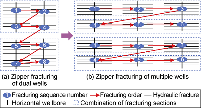
To get wellbore safety and maximum SRV, fracturing stimulation was conducted with the help of an early warning system and an optimized operation mode which is “multi-well zipper fracturing” developed on “double- well zipper fracturing”. Inter-well interference and stress focus became less (Fig. 6 ). By fully using superposition effect, and optimal fracturing scale and parameters, the fracture-controlled reservoir volume reached the maximum, and deformed sections reduced to 0.8 per 100 sections while getting safe stimulation.
Fig. 6. Schematic diagram of multi-well zipper fracturing. |
The shale oil development in the Jiyang continental rift lake basin has undergone multiple iterations and upgrades in terms of development, drilling and fracturing technologies. Production increased rapidly after single well evaluation and pilot well group, and the initial development result is satisfactory. In 2023, the new production capacity was 30 × 104 t, yearly oil production was 32.8 × 10⁴ t and cumulative oil production was 53.2 × 10⁴ t. By December 31, 2023, 64 horizontal wells had been put into production, and the oil production was 1 363 t/d and the water cut was 66.2%. Through multiple technological iterations, the investment per exploration and evaluation well has been reduced by 35%, and the investment per pilot well group has been further reduced.
3. Future improvement on shale oil development technology
Preliminary achievements have been made on pilot well groups for shale oil development in the Jiyang continental rift lake basin. However, there is still a significant distance from the United States in development technology and industrial scale. More improvements shall be made on shale oil development technology, engineering process and equipment.
3.1. Integrated development
Technological iteration shall focus on integrated and lifecycle development which should cover reserve control, producing reserves, inter-well interference, and production. (1) The differences in the spatial distribution of lithofacies, mineral composition, and oil-bearing properties should be comprehensively considered according to the geological characteristics of the shale oil reservoir in the continental rift lake basin, and the adjacent lithofacies with similar reservoir, oil-bearing and mechanical properties should be classified into a group. (2) Grading evaluation standards shall be established for evaluating geological, engineering and economic sweet spots, and vertical and horizontal favorable zones, and development priority shall be proposed in the entire region. Key indicators such as horizontal section length, well spacing, and interlayer spacing can be optimized to maximize the control of favorable sweet spots and reserves. (3) Considering well pattern and structural variation, a three-dimensional fracturing design shall be set up with optimal fracturing parameters, well spacing, and interlayer spacing. Integrated simulation shall be conducted to predict fracture propagation, provide early warning on inter-well interference, optimize fracturing operation sequence and parameters, and mitigate systemic fracturing risks to achieve full reservoir stimulation. (4) Post-fracturing optimization and control should be implemented throughout the entire lifecycle after putting into production, including real-time updating working system, differentiated chokes and producing order, prorating well production, and mitigating stress sensitivity to ensure long and stable production and the highest producing reserves, recovery, and profit.
3.2. Precise engineering technology
Precision of engineering technology determines the overall effects of shale oil development. Using the integrated drilling tracking and fracturing technology based on a geological model, the drill-in ratio of a 7 m to 12 m thick target is over 98% in Jiyang shale oil development. The design accuracy of the target has been improved to 3 m to 5 m as the evaluation of shale oil sweet spots became more precise, but higher demands were placed on engineering technology and equipment. (1) Drilling process must be carefully designed, precisely guided, and accurately targeted. A technical indicator system should be established to form industry standards and promote technological innovation and development. (2) Differentiated optimization should be performed for bit, casing, drilling fluid system, and ground support equipment based on a detailed evaluation of the geological conditions, such as structural undulation, lithofacies variation, and fault development along the entire wellbore trajectory. This will enhance the quality and efficiency of one-trip drilling. At the same time, monitoring parameters such as drilling pressure, torque, drilling rate, and drilling fluid properties should be strengthened to form a real-time optimization and control mode that can continuously improve drilling quality and efficiency. (3) High values of fracturing parameters may not be the best, but scientific optimization is the best means to improve them. Foreign shale oil reservoirs face a small stress difference, so it is easy to induce complex fracture networks. However, the continental shale oil reservoirs in China are under a larger stress difference and significant variation in fracture propagation, so continuous technological iteration is necessary. With complex fault system and local stress, it is easy to activate natural fractures when fracturing the continental shale oil reservoirs in China, even fault slipping and casing damage. To ensure both drilling safety and SRV, it’s necessary to develop optimal fracturing design and parameters.
3.3. Differentiated engineering technology indicator system
The engineering technology indicator system serves as an important basis for evaluating the effects of shale oil drilling and fracturing operations. Currently, some indicators adopted in the engineering technology indicator system are not very definite and require further precision in China. To this end, the integration of geological, engineering, and economic considerations must be deepened to establish an economically effective engineering technology indicator system that caters to the overall need of shale oil development under different geological conditions.
According to the geological characteristics of shale oil reservoirs in the Jiyang continental rift lake basin, engineering technology should focus on economic, safe, and effective drilling operation while maximizing SRV. Therefore, the indicator system should be optimized to include new metrics such as drilling cycle and drill-in ratio of favorable lithofacies, drilling and completion costs, safety and fracturing scale, effective stimulated reservoir volume (ESRV), ESRV per unit cost, recoverable reserves per well, and recoverable reserves per kilometer of wellbore. Differentiated strategies should be adopted for different shale oil reservoirs in different sags. A multi-level and multi-dimensional engineering technology indicator system should be established to effectively support the iteration of engineering technology for shale oil reservoirs in the continental rift lake basin.
3.4. Intelligent engineering equipment
Intelligent technology is important for improving production efficiency and optimizing decision-making, and it has been widely applied in the United States. By automatically matching over 190 000 fracturing operation reports from 100 000 wells in Fracfocus 2.0, the United States is able to resolve most fracturing engineering issues. With the development of shale oil reservoirs in the continental rift lake basin, the amount of data is expected to grow exponentially. Therefore, it is necessary to draw on US practices and establish an intelligent optimization and decision-making platform to support intelligent decision-making for field drilling, fracturing, and other engineering processes.
In intelligent drilling operation, automatic drilling technology should be researched to reduce manual intervention, shorten drilling cycle, and improve drilling accuracy. Efforts should also be made to optimize drilling sensors, remote monitoring equipment, and other devices to monitor the drilling process in real-time and automatically collect monitoring data. Through big data, artificial intelligence, and other technologies, potential risks such as trajectory deviation and wellbore collapse can be predicted in advance, and parameters such as drill bit orientation and drilling fluid properties can be adjusted in real-time to ensure the safety and efficiency of the drilling process.
In intelligent fracturing operation, research should be focused on the development of intelligent fracturing diagnostic technology. This technology can intelligently identify potential problems and failures based on changes in fracturing operation curves, providing early warnings and allowing for corresponding adjustment measures to be taken. Therefore, it can reduce manual intervention and shorten analysis cycle. Furthermore, by integrating microseismic data with other information, focus should be shifted to intelligent monitoring and positioning of fracture propagation. This technology enables real-time monitoring location and direction of induced fractures and optimizing pumping plan and fracturing parameters, with the intent to enhance fracturing efficiency and stimulation results.
3.5. Application of complex structure wells
Wells with complex structures can significantly reduce the number of wells, shorten development cycle, increase reservoir contact, reduce development costs, and enhance development effects. In the United States, various types of complexly structured wells have been drilled in shale oil reservoirs. For example, OXY made sequential development of multiple layers using multi-branch wells in the Permian Basin, and Matador applied U-shaped horizontal well development in the Delaware Basin. They both achieved promising results. Currently, shale oil development primarily relies on conventional horizontal wells in China. In the next phase, it is essential to research the integrated design of drilling and completion for complexly structured wells, window cutting technology and supporting tools, completion processes, integrated fracturing techniques for multi-branch wells, and efficient development technologies. This research should be tailored to the geological characteristics of shale oil reservoirs in continental rift lake basins in China, and aims to further enhance production, reduce costs, and improve efficiency.
3.6. Full-process integrated management
Shale oil development is a systematic engineering, and insufficient execution at any stage may cause severe consequences. After more than 20 years of iterative improvements, North American shale oil and gas development has promoted to establish a closed-loop development optimization process, an industrialized drilling and production mode, and a comprehensive and integrated management system. Shale oil development requires multiple resources and chains, and it’s a long cycle. Now shale oil development in China is still in its initial stage. A preliminary field-research-linked management mechanism has been formed, but there is still room for improvement on resource mobilization, construction optimization, schedule control, and quality inspection. To address these challenges, it is necessary to further deepen the integration of geological and engineering, strengthen basic theoretical research, improve regulation compliance in program planning, optimize engineering construction standards, and establish a sound and efficient implementation and oversight mechanism. This will lead to the formation of an integrated quality management and control system from design to implementation, ensuring sufficient demonstration, full execution, and implementation of every stage. All these efforts will support the effective development of continental shale oil in China.
4. Conclusions
Shale oil in continental rifted lake basins in China is different with marine shale oil in North America in terms of geological conditions, so we cannot exactly copy the development technology from North America. Relying on the iterative advancements in drilling and fracturing technologies, the United States has achieved a large-scale beneficial development of shale oil reservoirs, providing valuable insights for the scale and economic development of shale oil reservoirs in continental rift lake basins in China. Based on independent innovation, shale oil development in the Jiyang continental rift lake basin has established a series of highly efficient technologies. Continuous iterations of development technology have contributed to the precision of sweet spot evaluation, well pattern optimization, and well spacing design. Similarly, drilling technology iteration keeps moving forward through optimization of well structure, enhancement of drilling fluid system, and the development of high-end equipment and tools. A big progress has been made, including an optimized and efficient drilling technology system centered on “three-section well structure, synthetic drilling fluid, precise pressure control, high-temperature resistant rotary steerable system, and ground cooling”. Furthermore, fracturing technology has undergone three major iterations, including fracture network fracturing, dense cutting volume fracturing, and extremely limited entry dense cutting volume fracturing. All these achievements mark a significant leap in shale oil fracturing technology.
The pilot development of shale oil in Jiyang continental rift lake basin has achieved initial results. However, compared with the development of shale oil in the United States, there is still a big gap in large-scale beneficial development of shale oil in continental rift lake basins in China. To shorten the gap, more efforts need to make to strengthen overall development, enhance precision of engineering technology, improve engineering technical indicator system, accelerate intelligent optimization of engineering equipment, and explore the application of complexly structured wells. A comprehensive quality management system should be established that covers the entire process from design to implementation. This system will help expedite the iterative improvements in drilling and fracturing technologies for shale oil development in continental rift lake basins. All the efforts will ultimately drive and achieve the large-scale beneficial development of shale oil in the continental rift lake basins in China.