

Introduction
The successful development of unconventional resources has revolutionized the petroleum industry. This transformative shift has ushered in a new era characterized by a paradigm shift from resource competition to technological innovation and from production capacity rivalry to cost-efficiency optimization [1]. The development of unconventional resources has also propelled the need for a range of innovative technologies, such as horizontal wells [2], hydraulic fracturing [3], shale/tight oil EOR technologies [4], new technologies for oil sand, heavy oil, shale, and natural gas hydrate exploitation [5]. The advancement in technology has also driven the breakthroughs of classical petroleum geology theory [6].
Petroleum geology is an applied fundamental discipline that studies the origin, accumulation mechanism, and distribution of hydrocarbons in the Earth crust. It serves as the theoretical basis for oil and gas exploration and development. The core theories include: (1) The theory of basin subsidence-induced heating and pressurization, hydrocarbon generation, and petroleum system; (2) The theory of hydrocarbon reservoirs consisting of rock skeleton, effective pore space and filled movable fluids; (3) The theory of hydrocarbon distribution in petroleum basins, plays, traps and pools; and (4) The theory of petroleum development, which holds that hydrocarbon flow is generated and controlled under fluid pressure differences at different parts of reservoirs formed by human interventions according to the laws of conservation of energy and matter. Specifically, the petroleum system theory plays an important role in classical petroleum geology, as it forms the foundation for understanding the hydrocarbon generation, migration, and accumulation processes in the basin, and also serves as a guiding tool for oil and gas exploration [7].
Unconventional resources go beyond a lot of cognitive limitations in classical petroleum geology, and greatly impact the traditional theory of the petroleum system in the following aspects. First, following the continuous hydrocarbon accumulation theory [8], unconventional hydrocarbons are distributed continuously in a large area, which breaks the traditional concept of hydrocarbon accumulation in traps and enrichment in plays [9]. Second, the nanoscale pore throat system is found in tight reservoirs, and new types of unconventional oil and gas reservoirs (e.g. tight sandstone and shale) are discovered [10]. Third, unconventional hydrocarbons correspond to source rocks and reservoir rocks in the same suite of strata, instead of the traditional source-reservoir-caprock assemblage. Fourth, unconventional hydrocarbon accumulation is not dominated by buoyance, but by non-buoyance, which breaks the model of hydrocarbon generation, migration and accumulation under the petroleum system theory [11-12]. Magoon et al. [13] proposed the concept of “total petroleum system”, and pointed out the correlation between conventional and unconventional hydrocarbons in spatial distribution, but they did not form a systematic theory and research on relevant mechanism.
Jia et al. [14] presented the concept of “whole petroleum system” and indicated that the breakthrough of unconventional resources reveals a major defect of the traditional petroleum system theory, that is, it only involves conventional hydrocarbons. They recommended that a new theoretical framework of the whole petroleum system should be established in petroleum geology, and it should include the whole accumulation elements, whole formation & evolution process, whole resource distribution sequence, and whole prediction & evaluation aspects concerning conventional and unconventional hydrocarbons within petroleum basins. From the perspective of “source-reservoir coupling and orderly accumulation” rather than “from source to trap”, for both conventional and unconventional resources which include long-migrated, shortly-migrated, and retained hydrocarbons, the accumulation mechanism is analyzed with consideration to the four important theoretical issues in the quantification of the whole process of hydrocarbon generation, expulsion, migration and accumulation, and thus the whole process of hydrocarbon generation, migration and accumulation is clarified [15]. The theory of the whole petroleum system has been formed through research efforts in recent years.
The whole petroleum system is defined as a natural system of all geological elements and geological processes involved in the course that the hydrocarbons are generated by one or more sets of interrelated effective source rock formations in a petroleum basin, accumulated continuously in unconventional reservoirs or in conventional traps, and later adjusted and reworked [16]. The whole petroleum system theory includes: (1) the structure of the whole petroleum system in the petroleum basin; (2) the pattern of conventional oil/gas-tight oil/gas-shale oil/gas sequential accumulation; (3) the hydrocarbon accumulation model of the whole petroleum system; (4) the unconventional hydrocarbon accumulation mechanism (self-containment); (5) the geological model, flow model and production mechanism of shale and tight reservoirs; (6) the buoyance-driven accumulation and Darcy flow characteristics of conventional hydrocarbons; and (7) the controls of geodynamic process, hydrocarbon generation process and sedimentary system in the petroleum basin on the whole petroleum system.
1. Structure of the whole petroleum system
The whole petroleum system is a fluid system composed of various geological elements such as source rock, reservoir, oil, gas, water, and fluid dynamic field. Experimental studies and development practices have proved that many factors affect and control the migration and accumulation of oil and gas, including reservoir physical properties and structure, fluid properties, source kitchen evolution, and underground temperature and pressure fields. In the process of reservoir upward-densification, the whole petroleum system includes three fluid dynamic fields (Darcy flow dynamic field, limited Darcy flow dynamic field, and confined dynamic field), three types of oil and gas reservoirs/resources (conventional oil/gas, tight oil/gas, and shale oil/gas), and two types of hydrocarbon accumulation process (buoyance- driven conventional hydrocarbon accumulation process, and self-containment unconventional hydrocarbon accumulation process).
1.1. Three fluid dynamic fields
Due to the differences in pore scale and pore wall composition at different depths of petroleum basins, fluid migrates in different dynamic fields. The whole petroleum system theory involves three fluid dynamic fields: Darcy flow (free) dynamic field, limited Darcy flow dynamic field, and confined dynamic field (Fig. 1 ).
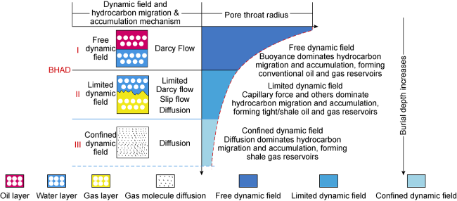
Fig. 1. Three dynamic fields in the whole petroleum system (according to Reference [15]). |
(1) Darcy flow (free) dynamic field. It mainly exists in conventional reservoirs. The reservoirs have high porosity (usually greater than (10±2)%), high permeability (greater than 1×10⁻³ μm2), and large pore radius (greater than 1 μm). In the Darcy flow dynamic field, the hydrocarbons migrate following the conventional Darcy law, accompanied by conventional hydrocarbon accumulation.
(2) Limited Darcy flow dynamic field. When the pore throat radius reduces to 0.025-1.000 μm and the permeability decreases to (0.01-1.00)×10-3 μm2, the hydrocarbons no longer migrate following the conventional Darcy law, and there is mainly limited dynamic field in the formation. At this time, the migration process often presents the characteristics of limited Darcy flow, slip flow, and even diffusion, for which the flow mechanisms and processes are difficult to be described. As a result, tight oil/gas and shale oil/gas are accumulated.
(3) Confined dynamic field. When the formation is extremely tight, the pore throat scale is very small, and there is mainly confined dynamic field in the formation. At this time, the large-molecule oil phase cannot even migrate in the formation, but only small-molecule methane can migrate in the form of diffusion. The flow phenomenon and flow mechanism are very complicated.
1.2. Three types of oil and gas reservoirs/resources
The coupling of reservoir upward-densification with the hydrocarbon generation, migration, and accumulation process determines the general coexistence of three types of resources, i.e. conventional oil/gas, tight oil/gas, and shale oil/gas, in the whole petroleum system.
Hydrocarbons are formed and generated in the source rocks and accumulated in the shale reservoirs to form shale oil/gas resources. Then, hydrocarbons charge and migrate into the tight reservoirs where hydrocarbons accumulate to form tight oil and gas reservoirs. In the buoyance-driven conventional hydrocarbon accumulation process, hydrocarbons accumulate in traps to form conventional oil and gas reservoirs (Fig. 2 ).

Fig. 2. Model of conventional oil/gas-tight oil/gas-shale oil/gas sequential accumulation in the whole petroleum system in the Junggar Basin, NW China (according to Reference [19]). (a) Shallow-medium: conventional multi-layer reservoirs that have been discovered, with buoyance-driven hydrocarbon accumulation, high porosity, high permeability and high production; (b) Medium-deep: Triassic Baikouquan Formation and Permian Upper Wuerhe Formation tight reservoirs, non-buoyance migrated hydrocarbon accumulation, low porosity, low permeability and low production; (c) Deep and ultra-deep: Permian Fengcheng Formation shale reservoirs, non-buoyance retained hydrocarbon accumulation (according to Reference [15]). P1j1—Lower Jiamuhe Formation of Lower Permian; P1j2—Middle Jiamuhe Formation of Lower Permian; P1j3—Upper Jiamuhe Formation of Lower Permian; P1f—Fengcheng Formation of Lower Permian; P2x—Xiazijie Formation of Middle Permian; P2w—Lower Wuerhe Formation of Middle Permian; P3w—Upper Wuerhe Formation of Upper Permian; T1b—Baikouquan Formation of Lower Triassic; T2k—Kelamay Formation of Middle Triassic; T3b—Baijiantan Formation of Upper Triassic; J1b—Badaowan Formation of Lower Jurassic; J1s—Sangonghe Formation of Lower Jurassic; J2x—Xishanyao Formation of Middle Jurassic; K—Cretaceous. |
1.3. Two types of hydrocarbon accumulation process
The hydrocarbon accumulation process involves the migration, accumulation, and adjustment mechanisms of hydrocarbons generated. The hydrocarbon accumulation processes of the whole petroleum system can be divided into: buoyance-driven conventional hydrocarbon accumulation process, self-containment unconventional hydrocarbon accumulation process, and the boundary of the two, that is, the buoyance-driven hydrocarbon accumulation depth (BHAD) [17].
1.3.1. Buoyance-driven conventional hydrocarbon accumulation process
White [18] proposed the theory of buoyance-driven hydrocarbon accumulation. To be specific, the conventional hydrocarbon accumulation is centered on trap enrichment and hydrocarbon preservation. The process is driven by buoyance and resisted by capillary force and viscous force. Ultimately, hydrocarbons stop migrating under the shield of caprock and accumulate in traps to form reservoirs.
Hydrocarbons migrate and accumulate in porous water-bearing reservoirs. In the migration process, under the action of buoyance, hydrocarbons leave the source rock and enter into the reservoir rock to begin the secondary migration. When the column height reaches a certain level and the buoyance of the oil and gas in the formation is greater than the resistance, hydrocarbons begin to migrate upward. The buoyance-driven conventional hydrocarbon accumulation theory explains the pattern of hydrocarbon accumulation in high parts of the basin and guides the exploration and discovery of conventional oil and gas.
1.3.2. Self-containment unconventional hydrocarbon accumulation process
Unconventional hydrocarbons (incl. tight oil/gas, and shale oil/gas) are difficult to form Darcy flow due to tight reservoirs. Or, the viscous oil (heavy oil, oil sand) is difficult to flow. Thus, the capillary force and viscous force in the reservoir are greater than the buoyancy force, disabling buoyance-driven hydrocarbon accumulation. Usually, unconventional hydrocarbons correspond to the so-called non-buoyance-driven accumulation. Jia et al. [19] defined this process as a self-containment hydrocarbon accumulation, which is driven by intermolecular force, including capillary force and viscous force. Under the action of strong hydrocarbon-generating-induced expansion force, hydrocarbons are charged into tight reservoirs due to the source-reservoir pressure difference, and preserved to form reservoirs under the action of capillary force and viscous force before they are released during artificial fracturing.
2. Conventional oil/gas-tight oil/gas-shale oil/gas sequential accumulation pattern and distribution model
In the whole petroleum system theory, conventional oil/gas, tight oil/gas, and shale oil/gas are orderly in formation time and spatial distribution. They present the sequence rationality based on genetic mechanism, and show the pattern of “sequential accumulation”. A variety of sequential accumulation models have been found in continental and marine basins, and they are believed to be mainly controlled by sedimentary systems of basins.
2.1. Types of sequential accumulation in continental basins
Continental sedimentary systems are complex in source-reservoir coupling, resulting in a variety of sequential accumulation models in continental basins.
2.1.1. Model of Permian in the Junggar Basin
The Permian system in the Junggar Basin is a saline lake formed in the setting of rapid tectonic subsidence, and it presents a complete oil and gas sequence, with the generated hydrocarbons migrating upward and charging. The whole petroleum system following this model develops conventional, tight, and shale oil reservoirs in a sequence upwards vertically (Fig. 2 ).
Conventional oil reservoirs are mainly distributed in the Jurassic Badaowan Formation (J1b) and the Triassic Baijiantan Formation (T3b) and the Kelamay Formation (T2k), with an average porosity of about 17.5% and an average permeability of 2.005 3×10⁻³ μm2.
Tight oil reservoirs are distributed in the Triassic Baikouquan Formation (T1b) and the Permian Upper Wuerhe Formation (P3w). The reservoirs are mainly composed of tight conglomerates, showing the characteristics of continuous distribution without obvious boundaries. The reservoirs are about 40-80 m thick, with the porosity of less than 10% and the permeability of (0.001-1.000)×10-3 μm2. Single-well productivity is low as 20-30 t/d for horizontal wells in the Mahu Sag, and the gas-to-oil ratio (GOR) is low as 100-200 m3/m3.
Shale reservoirs are distributed in the Permian Fengcheng Formation. They mainly record the process of non-buoyance-driven retained hydrocarbon accumulation. Several wells have achieved high oil and gas production in the source rock series of the Fengcheng Formation [20], confirming that shales will be the major exploration target in the Junggar Basin [21].
In the Permian in the Junggar Basin, hydrocarbons were generated from the source rocks of the Fengcheng Formation. Then, they were preferentially retained in the Fengcheng Formation to form shale reservoirs. Next, they continued to charge upwards to form tight oil reservoirs. Finally, they were accumulated in shallow conventional reservoirs to form conventional oil reservoirs. Thus, from shallow to deep strata, conventional oil, tight oil, and shale oil distribute sequentially.
2.1.2. Model of Yanchang Formation in the Ordos Basin
Different from the Permian in the Junggar Basin, the Yanchang Formation in the Ordos Basin belongs to wide shallow lake deposit in the setting of structural stability and presents a “sandwiched” sequential hydrocarbon accumulation model.
Hydrocarbons were generated from the source rocks of the 7th member of the Yanchang Formation (Chang 7 Member) and then migrated vertically upwards and downwards to form reservoirs. From shallow to deep, the sequence of conventional oil-tight oil-shale oil-tight oil-conventional oil is formed (Fig. 3 ).

Fig. 3. Model of Triassic Yanchang Formation in the Ordos Basin (according to Reference [20]). |
The Chang 7 Member is a set of high-quality lacustrine source rocks, which are 50-110 m thick and cover an area of 8.5×10⁴ km2, with TOC values of 2%-18% and Ro values of 0.9%-1.2%, dominantly Type I and II kerogens. The shale oil sources are estimated to be 31.2×10⁸ t [22]. Hydrocarbons generated in the Chang 7 Member were expelled upwards and downwards respectively, and accumulated as tight oil continuously in the Chang 3-Chang 2, Chang 4+5-Chang 6 and Chang 8 intervals. Then, hydrocarbons further migrated upwards and downwards, and finally formed conventional oil and gas in the Chang 1 and Chang 9 members (Table 1 ).
Table 1. Parameters of the Triassic Yanchang Formation conventional oil, tight oil and shale oil reservoirs in the Ordos Basin (according to Reference [20]) |
| No. | Horizon | Reservoir type | Porosity/ % | Permeability/ 10-3 μm2 | Resources/ 108 t |
|---|---|---|---|---|---|
| 1 | Chang 1 | Conventional oil | 15.0 | 10.00-100.00 | 1.2 |
| 2 | Chang 3- Chang 2 | Tight oil | 12.0- 16.0 | 0.70-0.90 | 16.0 |
| 3 | Chang 4+5 -Chang 6 | Tight oil | 11.0 | 0.50-0.60 | 53.0 |
| 4 | Chang 7 | Shale oil | 8.5 | 0.12 | 31.2 |
| 5 | Chang 8 | Tight oil | 8.1 | 0.57 | 31.2 |
| 6 | Chang 9 | Conventional oil | 12.2 | 5.70 | 5.7 |
2.1.3. Model of Cretaceous in the Songliao Basin
During the Cretaceous, the Songliao Basin, NE China, evolved in six stages: pre-splitting dome formation, extensional splitting, faulting, faulting-depression, depression, and shrinkage. Continental deposits of nearly 10 000 m thick were filled in the basin. The Daqing Placanticline in the central depression area, a primary tectonic unit in the northern part of the basin, records a long-term stable development of delta sand bodies, and the Gulong Sag holds permanent and stable fine-grained deposits in the Qingshankou Formation [23]. From the Gulong Sag to the Daqing Placanticline, an orderly distribution of shale oil, tight oil, and conventional oil is found in the lateral direction (Fig. 4 ).
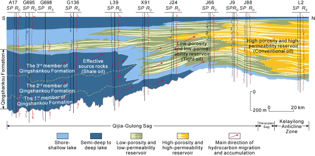
Fig. 4. Model of Cretaceous in the Songliao Basin. SP—self-potential, mV; RD—resistivity, Ω·m. |
Hydrocarbons were generated from the source rocks of the Qingshankou Formation in the Gulong Sag and then charged, migrated, and accumulated horizontally to the Daqing Placanticline. The Cretaceous Qingshankou Formation is a set of good continental source rocks, mainly type I kerogen, which are 15.78 m thick on average and cover an area of over 4×10⁴ km2, with TOC of 0.9%-3.8% and Ro of 0.5%-1.5%. The source rocks are in the peak period of oil generation and gas generation [24]. Hydrocarbons generated from these source rocks accumulated in the Qingshankou Formation in the process of self-containment retained hydrocarbon accumulation.
Driven by hydrocarbon-generating-induced expansion force, hydrocarbons migrated laterally, charged into the adjacent tight reservoirs of the Cretaceous Quantou Formation, and accumulated to form tight oil reservoirs under the self-containment effect dominated by capillary force. Then, due to buoyance, they continued to migrate and accumulated to form conventional oil reservoirs in the Placanticline. Compared with tight oil reservoirs, conventional oil reservoirs in the Daqing Placanticline are more developed.
There are various sequential hydrocarbon accumulation models in continental basins in China. They can be summarized as: (1) the model of Permian in the Junggar Basin with the sequential distribution of conventional oil, tight oil, and shale oil from shallow to deep strata, where hydrocarbons are generated from the source rocks at the bottom and charged vertically upwards; (2) the model of Yanchang Formation in the Ordos Basin with the sequential distribution of conventional oil, tight oil, shale oil, tight oil, and conventional oil from shallow to deep strata, where hydrocarbons are generated from the source rocks in the middle, and then charged upwards and downwards vertically; and (3) the model of Cretaceous in the Songliao Basin with the sequential distribution of conventional oil, tight oil, and shale oil on the plane, where hydrocarbons are generated from the source rocks and then charged in the planar direction.
2.2. Types of sequential accumulation in marine basins
The whole petroleum systems in marine basins also show different models. Typical models in marine carbonate basins in the United States include the model of the Bakken Formation in the Williston Basin and the model of the Wolfcamp Formation in the Permian Basin, North America.
2.2.1. Model of Bakken Formation in the Williston Basin
Shale oil/gas development in the United States began with the Bakken Formation in the Williston Basin [25]. The Bakken shale play (Upper Devonian-Lower Mississippi) consists of three intervals: upper, middle, and lower (Fig. 5 ).

Fig. 5. Model of Bakken Formation in the Williston Basin (modified according to Reference [26]). |
The upper and lower parts of the Bakken Formation (U. Bakken and L. Bakken) are black shales, rich in type II kerogen, and mainly oil-generating. The shales have TOC values of 7.23%-12.90%, Ro values of 0.65%-0.90%, porosity of about 3%, and very low permeability. The middle part of the Bakken Formation (M. Bakken) consists of grayish- brown very fine-fine conglomerates, dolomitic sandstone, and siltstone, and is poor in organic matter. Compared with U. Bakken and L. Bakken, M. Bakken has better physical properties, with the maximum porosity exceeding 8%.
Hydrocarbons were generated from the source rocks of U. Bakken and L. Bakken and retained to form shale reservoirs under the action of self-containment. Then, due to the hydrocarbon-generating-induced pressure difference, hydrocarbons charged and migrated into M. Bakken, where tight oil reservoirs were formed in the lower part and conventional oil reservoirs were formed in the areas with good physical properties in the upper part.
The Bakken Formation in the Williston Basin, North America, presents a “sandwiched” distribution of shale oil-conventional oil-tight oil-shale oil from shallow to deep strata, with a complete sequence.
2.2.2. Model of Wolfcamp Formation in the Permian Basin
The Permian Basin, a marine carbonate basin located in Texas and New Mexico, southwestern United States, is the third largest tight oil producing province (after Bakken in the Williston Basin and Eagle Ford in the western Gulf Basin) in North America, with the oil production recording a new high of 580×104 bbl/d [26-27]. The Permian Basin consists of the Midland sub-basin in the east and the Delaware sub-basins in the west, with the Central Basin Platform in the middle (Fig. 6 ).

Fig. 6. Model of Permian Basin in the United States. |
The Carboniferous-Permian Wolfcamp Formation is the main interval for unconventional oil and gas exploration and development. It is mainly distributed in the Delaware and Midland sub-basins, with a thickness of about 600 m. Conventional oil and gas are endowed in the Central Basin Platform and the margins of sub-basins. Currently, conventional hydrocarbons are being explored and developed in the mature stage, while unconventional hydrocarbons such as tight oil and shale gas are in the early stage. Both resources are hugely potential.
From top to bottom, the Permian Wolfcamp Formation can be divided into four members: Wolfcamp A, Wolfcamp B, Wolfcamp C, and Wolfcamp D. Typically, Wolfcamp D develops pure shale oil reservoirs, which are mainly distributed in southern and eastern Midland sub-basin. Wolfcamp D is a set of very good source rocks, with high TOC (average 3.25%). Most samples have TOC greater than 1%, and 82.65% of the samples exhibit TOC greater than 2%.
Hydrocarbons were generated from Wolfcamp D, and accumulated as retained hydrocarbons under the effect of self-containment. Then, hydrocarbons charged and migrated upwards to the upper part of Wolfcamp where hydrocarbons were accumulated to form tight oil and gas reservoirs. Next, hydrocarbons migrated further horizontally and vertically to the Central Basin Platform and the margins of sub-basins where hydrocarbons were accumulated to form conventional oil and gas reservoirs. A complete sequence of conventional oil/gas-tight oil/gas- shale oil/gas is distributed both horizontally and vertically.
The model of the Bakken Formation in the Williston Basin is close to that of the Yanchang Formation in the Ordos Basin, both showing “sandwiched” oil and gas distribution characteristics. The model of the Wolfcamp Formation in the Permian Basin is similar to the model of the Cretaceous in the Songliao Basin. Hydrocarbons experienced vertical migration and also horizontal migration before they were accumulated to form a sequential distribution model.
3. Hydrocarbon accumulation model of the whole petroleum system
From the perspective of the whole petroleum system theory, hydrocarbons migrate and accumulate in the formations. This process has differences and similarities in basins, which can be summarized to form the hydrocarbon accumulation model of the whole petroleum system (Fig. 7 ). The hydrocarbon accumulation model of the whole petroleum system has the following characteristics:
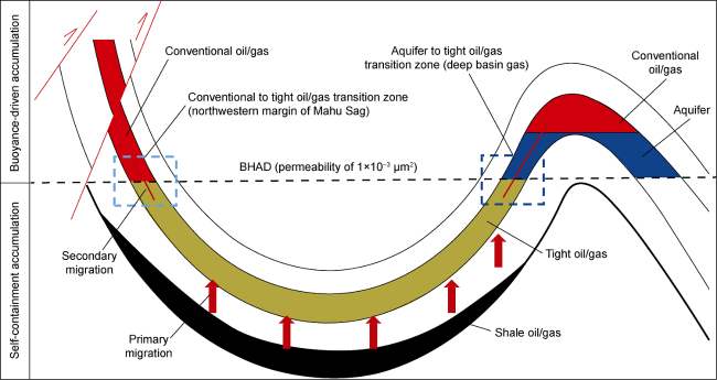
Fig. 7. Hydrocarbon accumulation model of the whole petroleum system. |
(1) This model is based on the theory of hydrocarbon generation by organic geochemical kerogen and the latest progress in the study of the diagenetic evolution history of sedimentary reservoirs. In particular, it holds that the physicochemical energy generated by kerogen hydrocarbon evolution is the main driving force for hydrocarbon migration and accumulation in source rocks and tight reservoirs (Fig. 8 ).
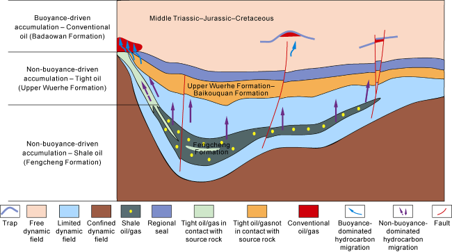
Fig. 8. Hydrocarbon accumulation model of the whole petroleum system in Permian, Mahu Sag, Junggar Basin. |
(2) This model includes conventional and unconventional hydrocarbon accumulation models.
(3) According to this model, the source-reservoir coupling relationship during the evolution significantly controls hydrocarbon expulsion efficiency, and the enrichment degree and proportion of conventional oil/gas, tight oil/gas, and shale oil/gas respectively, during the hydrocarbon accumulation of the whole petroleum system, involving clastic rock and carbonate basins/reservoirs (Fig. 9 ).
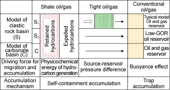
Fig. 9. Source-reservoir coupling and hydrocarbon migration & accumulation model of the whole petroleum system. S1 and S2 represent two models of clastic rock basins. |
(4) This model is built from the observation and statistical analysis of large-scale hydrocarbon accumulation patterns, such as the high-GOR giant carbonate oil reservoirs and the low-GOR clastic oil reservoirs, and the development patterns of giant unconventional hydrocarbon-enriched zones, in the world.
3.1. Hydrocarbon accumulation model of clastic rock basin
In clastic rock basins, the sandstones very close to the source rocks shows deposited and evolved in a process of normal continuous compaction, and became gradually densified with the basin subsidence. High-porosity and high-permeability reservoirs are formed in shallow strata, and tight sandstone reservoirs exist in deep strata. Moreover, at the margins of the basins, the reservoirs transit to conventional medium- to high-permeability ones upwards and farther. A close source-reservoir coupling relationship is reflected.
A part of hydrocarbons generated by the source rocks may be accumulated and preserved in shales, due to the adsorption of hydrocarbons by the organic pores in the shales and the capillary sealing at small pore scale. Shale oil and gas reservoirs are widely distributed, with their “sweet spots” as targets for exploration and development. Typical examples include shale oil in the Chang 7 Member of the Ordos Basin, shale oil in the Fengcheng Formation of the Junggar Basin, and shale oil in the Qingshankou Formation of the Songliao Basin.
With the progress of hydrocarbon generation, under the action of the induced expansion force, a part of the hydrocarbons generated by the source rocks leave the shales and enter the adjacent sandstones through primary migration. The sandstones may be subjected to two cases with the degree of diagenetic densification. In the first case, deep sandstones change into tight sandstones, while the source rock enters the hydrocarbon generation stage. The hydrocarbons generated charge the adjacent tight sandstones to form tight oil/gas. Therefore, tight oil and gas reservoirs are often characterized by extensive continuous distribution, and their “sweet spots” are pursued in the process of exploration and development. Typical examples include the tight oil in the Chang 8 Member of the Ordos Basin, tight oil in the Baikouquan Formation of the Junggar Basin, and tight gas (deep basin gas) in the Shanxi Formation of the Ordos Basin. The hydrocarbons not preserved by the “self-containment effect” of tight formations pass through these formations, and then migrate under the action of buoyance in the high-porosity and high-permeability sandstones and accumulate to form conventional oil and gas reservoirs. A typical example is the Jurassic reservoirs in the Ordos Basin. In the second case, the shallow sandstones maintain high porosity and high permeability when the source rocks expel hydrocarbons, directly forming conventional sandstone oil reservoirs, such as large-scale low-GOR low-maturity oil reservoirs. The high-porosity and high-permeability reservoirs with low GOR in the Daqing Placanticline of the Songliao Basin indicate that the oil reservoirs might be formed in the early oil expulsion stage of shallow-medium source rocks.
3.2. Hydrocarbon accumulation model of carbonate basin/reservoir
Carbonate fractured-vuggy and porous-vuggy reservoirs do not experience strong compaction during basin subsidence, making the porosity and permeability remain unchanged. Carbonate rocks are entirely different from clastic rocks in diagenetic history and pore evolution history. Their biological and chemical processes occur in the early diagenetic stage. The porous-vuggy reservoirs include bioclastic rocks. The shallow dolomite weathering leaching porous-vuggy reservoirs are mainly formed in shallow strata near the surface, and the carbonate reservoirs are rarely affected by densification during deep burial. Therefore, these reservoirs can always accept hydrocarbons from source rocks efficiently from shallow to deep and have distinct characteristics of trap reservoir-forming. The igneous rock reservoirs have similar characteristics. This model can explain the differences in reservoir-forming characteristics between carbonate basins and clastic rock basins. For example, the large carbonate oilfield has a higher GOR than the large clastic rock oilfield, represented by the GOR of 80 in the Gaval oilfield, 99 in the Safaniyah oilfield, 524 in the Kashagan oilfield, and an extremely low value in the Daqing Placanticline, China. This model can also explain the great difference in the proportion of conventional oil and gas and the proportion of unconventional oil and gas in petroleum basins.
4. Mechanism of self-containment accumulation of unconventional hydrocarbons
The whole petroleum system theory unifies conventional and unconventional hydrocarbons. The accumulation mechanism of conventional hydrocarbons has been deeply understood, but the insights on the accumulation mechanism of unconventional hydrocarbons are still limited.
In the process of hydrocarbon accumulation, the final accumulation and preservation are very important. It has been known that conventional hydrocarbons migrate into traps with buoyance to accumulate and preserve. What is the mechanism of accumulation and preservation of unconventional hydrocarbons with continuous distribution? Jia et al. [19] proposed the concept and mechanism of self-containment accumulation of unconventional hydrocarbons. Self-containment of oil and gas refers to the geological process in which the unconventional hydrocarbons in the petroleum basin are isolated from the outside world and independently accumulated and preserved under certain conditions, depending on the intermolecular force within the hydrocarbons themselves or between the hydrocarbons and the reservoir medium interface. This effect does not occur at the boundaries of unconventional reservoirs, but within the reservoirs (Table 2 ).
Table 2. Dynamic mechanisms of self-containment accumulation of unconventional hydrocarbons (according to Reference [18]) |
| Classification | Self-containment | Critical conditions for self-containment | Typical examples | |
|---|---|---|---|---|
| Type of intermole- cular force | Deposit type | |||
| Molecular viscous force and cohesive force | Heavy oil reservoirs | The contraction during the degradation of organic matter increases oil density to form heavy oil, and the internal viscous force of molecules cause the oil to not migrate but accumulate under the effect of self-containing | Strong microbial degradation and oxidation; formation water salinity < 5 000 mg/L; temperature < 60 °C; depth < 2 000 m | Orinoco heavy oil belt, Eastern Venezuela Basin; western margin of Songliao Basin |
| Bitumen deposits | The molecular contraction during the degradation of organic matter transforms oil into bitumen. The density increase and thickening lead to self- containment accumulation of oil | Strong microbial degradation and oxidation; formation water salinity < 2 000 mg/L; temperature < 30 °C; depth < 1 000 m | Eastern margin of Alberta Basin, Canada; western margin of Junggar Basin; western slope of Liaohe Depression, Bohai Bay Basin | |
| Molecular interfacial force (capillary force) and adsorption force | Tight oil and gas reservoirs | Reservoirs become tight due to compaction, with the capillary force increasing to cause buoyance failure. As a result, hydrocarbons do not migrate but accumulate under the effect of self-containment | Capillary force within the reservoir exceeds oil and gas buoyance; porosity ≤ 12%; permeability ≤ 1×10⁻³ μm2; pore throat radius ≤ 1 μm | Deep basin gas reservoirs in the Rocky Mountains, USA; Paleozoic tight sandstone gas reservoirs in the Ordos Basin, China; tight conglomerate oil and gas reservoirs in the Mahu Sag, Junggar Basin |
| Coalbed methane reservoirs | Strong adsorption of oil and gas by coal organic matter negates buoyance effects, leading to self-containing within the coal seams | Coal seam porosity ≤ 5%; Coal seam permeability ≤ 0.01×10⁻³ μm2; Pore throat radius ≤ 0.025 μm | Walloon coal measures, Surat Basin, Australia; coalbed methane in the Qinshui Basin, China | |
| Shale oil and gas reservoirs | Adsorption by shale media and capillary force prevent oil and gas from migration, causing buoyance failure and self-containing | High TOC shale; porosity ≤ 12%; permeability ≤ 0.1× 10⁻³ μm2; pore throat radius ≤ 0.1 μm | Barnett shale gas, Fort Worth Basin, USA; shale oil and gas in the Sichuan Basin, China | |
| Molecular cage force | Natural gas hydrate deposits | Water molecules under high pressure and low temperature enclose methane and other natural gases into solid hydrates, leading to self-containing | Ocean floor or continental permafrost with hydrocarbon generation conditions; formation pressure of 2-15 MPa; temperature of 10-15 °C | North Slope Basin, Alaska, Arctic; South China Sea Basin, and Qinghai- Tibet Plateau, China |
The microscopic source of self-containment is the intermolecular force (Van der Waals force), which is a weakly basic electrical attraction between neutral molecules or atoms, including electrostatic force, induction force, and dispersion force.
The interaction of permanent dipole moments between polar molecules is called the electrostatic force. Between polar and non-polar molecules, one polar molecule polarizes the other molecule, generating induction dipole moments and attracting each other, which is called induction force. The movement of electrons in the molecule produces an instantaneous dipole moment, which instantaneously polarizes neighboring molecules, which in turn enhances the instantaneous dipole moment of the original molecule, and this mutual coupling produces an electrostatic attraction effect, called the dispersion force, also known as the London force.
The van der Waals forces that exist between fluid and fluid and between fluid and pore wall are the microscopic source of all self-containment effects.
For tight oil and gas reservoirs, the hydrocarbon charging is driven by the hydrocarbon-generating-induced expansion force, that is, source-reservoir pressure difference, and suffers capillary force as the resistance. The smaller the pore radius is, the larger the capillary force is, and the more difficult the pores are to be charged. Driven by the hydrocarbon-generating-induced expansion force, oil and gas overcome the capillary force and enter the reservoir (Fig. 10a ). When the hydrocarbon-generating-induced expansion force decreases or more dense areas are encountered in the process of hydrocarbon charging, oil and gas are “contained” in the tight reservoir, forming the “self-containment effect” of the tight reservoir (Fig. 10b ). This self-containment effect is “destroyed” in the process of oil and gas development due to fracturing and the change of formation pressure distribution, allowing oil and gas to be produced.
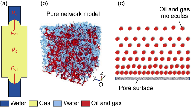
Fig. 10. Schematic diagram of self-containment of unconventional oil and gas (according to references [27-28]). (a) "Self-containment" within capillaries in tight reservoirs; (b) "Self-containment" of oil and gas in the pore network of tight reservoirs; (c) Adsorption "self-containment" near the pore surface in organic pores. pcl—capillary pressure; pg—gas phase pressure; pw—water phase pressure. |
There are both organic and inorganic pores in shale reservoirs. After the formation of hydrocarbons in organic matters, a part of the hydrocarbons is adsorbed on the pore surface under the action of intermolecular force (Fig. 10c ), forming a “self-containment effect”. The other part is charged into the inorganic pores, forming a “self-containment” under the action of capillary force. The combination of the two contributes to the “self-containment accumulation” of shale oil and gas. In the development process, when the shale reservoir is “opened”, due to the pressure drop, a part of the adsorbed oil and gas will be “desorbed” from the pore surface, and be produced under the pressure difference, thus destroying the “self-containment” state.
5. Geological model, flow model and production mechanism of shale oil/gas-tight oil/gas reservoirs
Shale and tight sandstone are new types of reservoir rocks, and shale and tight sandstone oil/gas are also new hydrocarbon resources discovered in recent years. In production practices, the horizontal well and volumetric fracturing technologies have made it possible to produce oil and gas, even at a high and stable rate, from tight reservoirs. This represents a significant achievement. However, the practice of unconventional oil and gas production is ahead of the theoretical understanding, and the insights on geological model, flow model, and production mechanism of shale oil/gas-tight oil/gas reservoirs are still preliminary and superficial, far behind those on conventional oil and gas. Such a new domain requires innovations in theory, technology, and method, and their research is still in progress.
5.1. Geological model
5.1.1. Storage space
The storage spaces of shale and tight oil/gas reservoirs are complex and diverse. Compared with conventional reservoirs, they have multiple scales and types as follows:
(1) Matrix micropores to nanopores, including isolated pores, and connected pores. They can also be connected with microfractures to form micro pores-fractures connected areas. Matrix micropores to nanopores are the main space for shale oil/gas and tight oil/gas storage.
(2) Microfractures, including structural fractures, rock- forming fractures, and hydrocarbon-forming fractures. They are the reservoir space of oil and gas, and also an important seepage channel on a microscopic scale, which greatly improves the microscopic fluidity in shale and tight reservoirs.
(3) Bedding/lamellation fractures, including the structural plane of the open fracture and the rock. They are the mechanical weak surfaces of the rock, and the fluid is easier to flow along the bedding. The direction of bedding may be the main direction of fracture initiation and propagation during fracturing.
(4) Induced fractures, including the main hydraulic fractures and the inherited fractures with weak surface. Fractures induced during fracturing extend in the direction perpendicular to the minimum principal stress. The reservoir with more developed mechanical weak surface (bedding) is more likely to form complex fracture networks and obtain a good fracturing effect.
5.1.2. Macroscopic homogeneity and mesoscopic/ microscopic heterogeneity of reservoirs
Shale and tight oil/gas generally have the characteristics of wide distribution. Macroscopically, the reservoirs are homogeneous, with large-scale continuous distribution, sequence control, and stable lithology and physical properties (Fig. 11a ). Mesoscopically, the reservoirs, tight generally, develop fractures (network) and pores in uneven distribution. The fractures include microfractures, bedding fractures, lamellation fractures, and fracturing-induced fractures (Fig. 11b ). Microscopically, pores and microfractures of different scales are distributed. Pores include isolated micropores-nanopores (organic or inorganic) and micro pores-fractures connected areas (micro-pore-fracture system) (Fig. 11c ).

Fig. 11. Multi-scale geological model of shale oil and gas reservoir. |
Shale and tight oil/gas reservoirs are relatively homogeneous at the macroscopic level, but highly heterogeneous at the microscopic level. Compared with conventional oil and gas reservoirs, shale and tight oil/gas reservoirs contain multi-scale storage spaces - from organic pores (at the nanoscale), to microfractures (at the microscale), and to induced fractures (at a larger scale). This leads to differences in oil and gas flow models.
5.2. Flow model
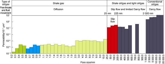
The pore throats of conventional oil and gas reservoirs are generally not less than 1-2 μm in size, where the flow of oil and gas conforms to the Darcy law. However, the flow regime of unconventional oil and gas is very different from that of conventional oil and gas. In multi-scale unconventional reservoirs, there are four flow patterns: Darcy flow, limited Darcy flow, slip flow, and diffusion (Fig. 12 ). Limited Darcy flow is an atypical seepage flow in shale and tight oil and gas reservoirs. It is controlled by heterogeneous fracture network, and characterized by unstable displacement pressure difference, diverse phase change, multiple flow patterns, and multi-phase mixing.
Fig. 12. Fluid movement characteristics of shale oil/gas, tight oil/gas, and conventional oil/gas (according to Reference [25]). |
In large pore throats or microfractures, oil and gas exhibit Darcy flow pattern, and follow the same flow mechanism as conventional oil and gas. In small pore throats, oil and gas show limited Darcy flow. For tight and shale oil/gas, they mainly follow limited Darcy flow pattern. In tiny pore throats, the oil phase cannot flow, while the gas phase shows the characteristics of slip flow or diffusion flow due to the confinement effect.
Unconventional oil and gas reservoirs span multiple scales, from nanopores to micropores, from microfractures to induced fractures, and from Darcy flow to diffusion flow, suggesting very complicated flow mechanisms and patterns.
5.3. Basic characteristics and production mechanism of tight and shale oil and gas reservoirs
5.3.1. Basic characteristics
5.3.1.1. Fractured-microporous tight oil and gas reservoirs with finite volume
Conventional oil and gas reservoirs have huge edges and bottom water, and they can be regarded as infinite volume. Shale and tight oil and gas reservoirs are layered fractured-microporous tight reservoirs, which can only be produced after fracturing, so called “artificial reservoirs”. Therefore, the range of reservoirs is the volume created horizontal well fracturing. In multi-well cube development or infill well pattern, interference and communication may occur between wells to form larger isolated reservoirs. Therefore, they are fractured-microporous reservoirs with finite volume.
5.3.1.2. Complex fluid composition and phase state
The underground fluid composition of shale and tight oil and gas reservoirs is complex, including gaseous state (e.g. dry gas, wet gas, condensate gas, and injected gas), and liquid state (e.g. light oil, black oil, minor formation water, and fracturing fluid). This challenges the development of technology.
The fluid phase has a great impact on the development of shale oil and tight oil. Typical developed shale oil and gas mainly include light oil with a high GOR, condensate oil, and black oil with a low GOR. Light oil with high GOR and condensate oil are characterized by strong gas swelling and good oil fluidity, allowing them to be produced easily. In North America, shale oil resources represented by light oil with high GOR and condensate oil have become the major contributor to the U.S. shale oil production. China has also obtained the light shale oil resources with high GOR and is building a demonstration area of shale oil in Qing 1 Member in the Gulong Sag of Daqing Oilfield. Low-GOR black oil plays an important role in shale oil resources in China and has recently achieved unexpected production results in the Jiyang Depression of Shengli Oilfield. This shows that low-GOR black oil is prospective, and more efforts are needed to understand shale oil underground.
5.3.1.3. Complex and diverse reservoir driving mechanisms
Shale and tight reservoirs can be recovered commercially only by fracturing. Shale and tight oil reservoirs are developed by various driving mechanisms, and the imbibition of fracturing fluid can also function to displace oil. The main driving mechanisms include overpressure formation elastic driving, high in-situ stress rock skeleton elastic driving, gas (including dissolved gas) elastic expansion driving, gravity driving, artificial pumping power driving, and so on.
Shale gas and tight gas generally show the characteristics of large-scale continuous distribution, without obvious edge and bottom water, and lack of edge and bottom water elastic driving compared with conventional oil and gas reservoirs.
5.3.2. Production mechanism and enhanced recovery techniques
Shale and tight reservoirs are different from conventional reservoirs in basic geological characteristics, leading to different production mechanisms and enhanced recovery orientations.
5.3.2.1. Production mechanism
Different from conventional hydrocarbons, shale oil/gas and tight oil/gas are preserved primarily by virtue of their self-containment effects. In other words, shale oil/gas and tight oil/gas are developed by breaking this self-containment effect. Essentially, these oil and gas are recovered by way of artificial fracturing that creates fractures to improve the reservoir permeability, change the capillary action, and increase the sweep volume and desorption specific surface area. The main ways to increase oil and gas production are displacement and imbibition.
5.3.2.2. Enhanced recovery techniques
The fundamental cause of low shale or tight oil/gas recovery is the low degree of employed reserves due to the self-containment effect of oil and gas. Three techniques can be adopted to enhance the recovery. One is to increase reservoir permeability. For example, volumetric fracturing technology is implemented with increased fracturing fluid volume and displacement pressure. The second is to change the capillary action. For example, new fracturing materials are designed to enhance the imbibition effect. The third is to increase the sweep volume and desorption specific surface area. For example, the horizontal section is increased, the fracturing scale is expanded, overall development is used, and re-fracturing is adopted.
The geological theory and development of shale oil/gas and tight oil/gas involve complex scientific and technical issues and are important domains worthy of theoretical innovation in the petroleum industry [29]. Unconventional oil and gas development in China is still facing a severe situation. More efforts are required to further understand the geological characteristics and production laws of these resources and then develop innovative technology and equipment for purpose of efficient development.
6. Research prospects
The whole petroleum system theory organically unifies conventional and unconventional hydrocarbons. It should be further studied vigorously. The future research will focus on:
(1) Characteristics of the whole petroleum system in carbonate basins and the source-reservoir coupling patterns in the evolution of composite basins. Carbonate rocks are significantly different from clastic rocks in diagenesis and diagenetic process. There have been many studies on the whole petroleum system of clastic rock basins, but the whole petroleum system in carbonate basins and the source-reservoir coupling pattern in composite basins have been scarcely investigated.
(2) Flow mechanisms in migration, accumulation, and production of shale oil/gas and tight oil/gas. Despite certain achievements, the exploration and development of shale oil/gas and tight oil/gas have been conducted ahead of the theoretical research. The insights on the flow mechanism of shale oil/gas and tight oil/gas migration, accumulation, and production remain limited. In this respect, further efforts are needed.
(3) Geological characteristics and enrichment of deep and ultra-deep shale oil/gas, tight oil/gas, and coalbed methane. China has made great progress in deep-ultra- deep oil and gas exploration, and is fully in the stage of “deep (water) and unconventional” exploration. China has become a major country engaged in onshore deep- ultra-deep oil and gas exploration and production. The deep-ultra-deep oil and gas resources still hold significant potential and will be important targets in the petroleum industry of China. It is necessary to deeply understand the geological characteristics and enrichment rules of deep-ultra-deep hydrocarbons.
(4) Resource evaluation and new generation of basin modeling technology of the whole petroleum system. The genetic method with basin simulation as the core has been widely used in exploration and production research. The main challenge for basin simulation is that the classical petroleum system theory is not effective for the evaluation of unconventional oil and gas resources. This challenge can be addressed by following the whole petroleum system theory. A new generation of basin simulation system should be established depending on the whole petroleum system theory and modern information technology.
(5) Research on earth system-earth organic rock and fossil fuel system-whole petroleum system. Earth system science focuses on the interaction between the components of the Earth to gain a scientific understanding of the entire earth system on a global scale. The formation and enrichment of organic rocks and fossil fuels are highly dependent on the evolution and interaction of biosphere and lithosphere (including sedimentation, tectonism, and other geological processes), hydrosphere, and atmosphere in geological history. These elements and their complex interactions constitute the earth's organic rock and fossil fuel system and become an important and special component and subsystem of the earth's system. The whole petroleum system is an important part of the earth's organic rock and fossil fuel system.
7. Conclusions
The breakthrough of unconventional resources reveals a major defect in the traditional petroleum system theory, that is, it only involves conventional hydrocarbons. The whole petroleum system theory organically unifies conventional and unconventional hydrocarbons, from a new perspective of “source-reservoir coupling and orderly accumulation” rather than “from source to trap”.
The main structure of the whole petroleum system includes three fluid dynamic fields (e.g. Darcy flow (free) dynamic field, limited Darcy flow field, and confined dynamic field), three types of oil and gas reservoirs/resources (e.g. shale oil/gas, tight oil/gas, and conventional oil/gas), and two types of hydrocarbon accumulation process (e.g. buoyance-driven conventional hydrocarbon accumulation process, and self-containment unconventional hydrocarbon accumulation process).
In the whole petroleum system theory, conventional oil/gas, tight oil/gas, and shale oil/gas are orderly in formation time and spatial distribution. They present the sequence rationality based on genetic mechanism, and show the pattern of “sequential accumulation”.
The hydrocarbon accumulation model of the whole petroleum system includes conventional hydrocarbon accumulation model and unconventional hydrocarbon accumulation model. It can be divided into two types: the typical hydrocarbon accumulation model of clastic rock basin and the special hydrocarbon accumulation model of carbonate basin where the medium-high permeability reservoir is directly in contact with the source rocks. The accumulation of unconventional oil/gas corresponds to self-containment, which is microscopically driven by the intermolecular force (or van der Waals force).
The geological model, flow model, and production mechanism of shale and tight reservoirs is a new and complex field that involves significant scientific and technical issues. In-depth innovations in theory, technology, and method are highly demanded. The shale revolution in China is still facing a severe situation, but shale oil/gas must be the most important resource replacement in the long-term oil and gas resources of China.