

Introduction
Carbon capture, utilization and storage-enhanced oil recovery (CCUS-EOR) is a technological process of capturing CO2 generated in the production process of electric power, cement, iron and steel, and coal chemical industry through absorption, membrane separation, pressure swing adsorption, and other technologies, and injecting it into oil reservoirs for oil recovery and long-term storage. CCUS-EOR can significantly enhance the oil recovery and realize CO2 emission reduction, which is an effective technology for large-scale low-carbon utilization of fossil energy, as well as an important way to achieve the goal of "dual-carbon" strategy [1⇓-3]. CO2 flooding and storage technology started earlier abroad and is mainly applied in the United States and Canada. CO2 flooding projects began to be constructed in the United States in the 1950s, and entered the commercialization and promotion stage after technology research and industrial demonstration in the late 1980s [4]. The United States became the country with the largest number of CO2 flooding projects in the world, accounting for more than 90% of the world's total. The annual oil production contributed by CO2 flooding has once reached about 1 500×104 t for five consecutive years to enhance the oil recovery by 7-15 percentage points [3,5]. The Weyburn oil field in Canada built the world's first CCUS-EOR demonstration project in 2000 [6], with an annual CO2 injection of (160-200)×104 t. The recovery was about 24% before CO2 injection, and the estimated ultimate recovery can be enhanced by more than 15 percentage points after CO2 injection [7].
The CO2 flooding and storage technology has gone through three stages in China: exploratory research, pilot test and industrialized application. (1) It has entered the early exploration stage since 1965. Shengli Oilfield, East China Oilfield, and Jiangsu Oilfield of China Petroleum and Chemical Corporation (Sinopec for short) carried out CO2 flooding tests. Daqing Oilfield of China National Petroleum Corporation (PetroChina) carried out carbonated water injection tests, and Jilin Oilfield successively carried out CO2 huff and puff, as well as CO2 test injection [7]. (2) It has entered the pilot test stage since 2006. Shengli Oilfield carried out CO2 near-miscible flooding pilot test in Gao 89-1 in 2007 [8], then implemented CO2 high- pressure miscible flooding pilot test and made a breakthrough in Fan 142-7-X4 well group in 2013 [9]. Jilin Oilfield had successfully performed CO2 flooding tests in Hei 59, Hei 79 South and Hei 79 North well blocks and achieved good application effects. Due to the limitation of CO2 source conditions, the construction scales of CO2 flooding and storage projects in China were generally small [10⇓⇓⇓⇓⇓⇓⇓⇓-19]. (3) It has entered the industrialized application stage since 2020. PetroChina has built four pilot test areas for CCUS-EOR in different types of reservoirs, including Daqing low permeability reservoirs, Jilin extra-low permeability reservoirs, Changqing ultra-low permeability reservoirs, and Xinjiang conglomerate reservoirs. They have carried out industrialized applications in Jilin Daqingzi wells and Daqing Yushulin extra-low permeability oilfield [10]. Sinopec Shengli Oilfield has established a theoretical and technological series of CO2 high-pressure miscible flooding and storage, and it completed a 100×104 t CCUS whole-process demonstration project in August, 2022.
This paper analyzes the major challenges faced by CO2 flooding and storage in Shengli Oilfield and systematically elaborates the theoretical understanding and key technologies of CO2 high-pressure miscible flooding and storage; then apply them to the field practice of the 100×104 t CCUS demonstration project, to provide a reference for the development and large-scale application of CCUS technologies in China.
1. Major challenges of CO2 flooding and storage in Shengli Oilfield
There are abundant resources suitable for CO2 flooding and storage in Shengli Oilfield, with about 15×108 t original oil in place (OOIP), dominated by deep low permeability reservoirs, accounting for 68.7% of the total. These reservoirs are facing challenges: the water cannot be injected into injection wells, and the oil cannot be recovered from production wells, which leads to low production capacity and low recovery. There is a huge potential to improve the recovery and storage factor. Compared with marine reservoirs in the United States, terrestrial reservoirs in Shengli Oilfield are characterized by low reservoir permeability, low light-hydrocarbon content of crude oil, high density and high viscosity of crude oil, and strong heterogeneity of the reservoir, etc. So, it is impossible to copy the foreign mature experience of CO2 flooding and storage, and the large-scale beneficial development is still confronted with the following major challenges: (1) The miscibility mechanism of CO2 with terrestrial crude oil with low light-hydrocarbon content is still unclear. It is generally believed that light hydrocarbons (C2-C6) are the key component to decide whether it can be miscible. The terrestrial crude oil in China is characterized by low light-hydrocarbon content, and the miscible is poor by the conventional development mode. Now most reservoirs are developed by near-miscible flooding, and enhanced oil recoveries are less than 10 percentage points. Therefore, whether or not miscible phase can be achieved in this kind of reservoir and methods for miscible flooding needs further research. (2) The development contradictions of CO2 flooding are complex and varied in different stages, with significant differences in oil and gas production characteristics, making it prone to gas channeling and difficult to control. Further research is needed on how to maintain high-pressure miscible throughout the CO2 flooding process. (3) For heterogeneous reservoirs, sedimentary facies vary rapidly, physical properties are significantly different in planar and vertical, CO2 flooding sweep efficiencies are low, and storage spaces are limited. Taking the beach-bar sandstone reservoirs in Shengli Oilfield as an example, the beach sandstone is interbedded with bar sandstone on the plane, with permeability ratios greater than 5, and vertically they are large in quantity and small in thickness with permeability ratios greater than 10. Further research is needed on how to expand the swept volume and achieve permanent safe storage under such complex heterogeneous conditions.
2. Theoretical understanding of CO2 high-pressure miscible flooding and storage
In response to the major challenges faced by the large- scale application of CO2 flooding in terrestrial oil reservoirs, Sinopec Shengli Oilfield Company has proposed the theoretical understanding of CO2 high-pressure miscible flooding and storage through continuous scientific exploration and field practice: the miscible ability of medium-heavy components can be improved by significantly increasing the reservoir pressure to 1.2 times the minimum miscible pressure or above; the production of crude oil in small pores can be increased through forming a high-pressure driving system. Controlling the leading-edge pressure and displacement front to reduce the impact of gas channeling significantly improves the recovery and storage factor.
2.1. High pressure accelerates gradient extraction for mass transfer and phase miscible of medium-heavy components
CO2 miscible flooding is a multiple-contact process, in which CO2 is pushed into the reservoir and contacts the oil multiple times to undergo bidirectional mass transfer before reaching a miscible state. CO2 continuously extracts light hydrocarbon components from crude oil during this process, while CO2 dissolves in the crude oil, forming a gas phase rich in light hydrocarbons and an oil phase with dissolved CO2. Eventually, the oil-gas interface disappears and reaches a miscible state. The interfacial tension tends to zero, and the flow ability of crude oil significantly improves after the oil is miscible with CO2 [20⇓⇓-23].
The bidirectional mass transfer capacity between CO2 and crude oil is determined by the hydrocarbon composition of the crude oil. An analysis and comparison were conducted on the marine crude oil in North America and terrestrial crude oil in Shengli Oilfield (Fig. 1 ). The content of light hydrocarbons (C2-C6) in marine crude oil in North America is 48.0%, and the distribution is relatively concentrated, with less content of medium and heavy components, so CO2 only needs to extract the C2-C6 sufficiently to achieve the miscible state. On the other hand, the content of light hydrocarbons (C2-C6) in the terrestrial crude oil of Shengli Oilfield is only 12.5%, and the main peak carbon is C13, so the prerequisite for CO2 to mix with crude oil is the fully bidirectional mass transfer with C7-C20, which is very difficult.
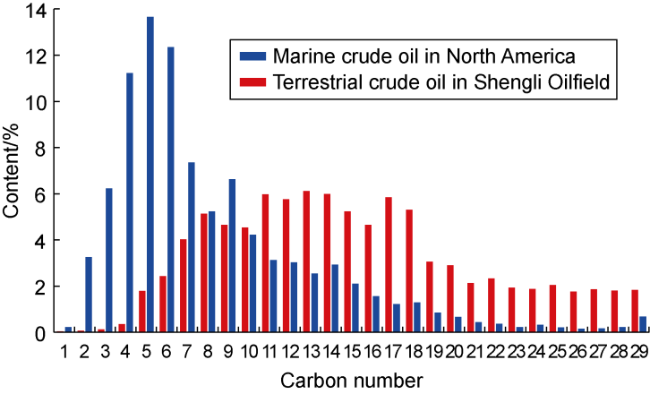
Fig. 1. Comparison of hydrocarbon components with different carbon numbers in crude oil in China and abroad. |
Aiming at the high content of medium-heavy components in the crude oil and the difficulty of miscible phase, extraction experiments of CO2 on crude oil were conducted under different pressures at formation temperature (110 °C), and the changes of hydrocarbon composition in the gas phase were analyzed (Fig. 2 ). The experimental results show that at 20 MPa, CO2 is mainly used to extract light hydrocarbons such as C2-C6 from crude oil. Some intermediate hydrocarbons, such as C7-C15 can also be extracted, but the C16+ components almost do not interact with CO2. Total hydrocarbons in the gas phase account for only 8.5%, and the interface between the oil and gas is clear and distinct now. When the pressure increases to 25 MPa, the extraction of CO2 on intermediate hydrocarbons such as C7-C15 is obviously increased, and heavy hydrocarbons such as C16-C20 are also effectively extracted. The proportion of total hydrocarbons increases to 14.5% in the gas phase, and the color of the gas phase at this time gradually becomes darker, but the oil-gas interface is still relatively obvious. When the pressure continues to increase to 30 MPa, the extraction amount of C16-C20 by CO2 increases significantly, and the proportion of total hydrocarbons in the gas phase increases to 18.4%. Then, the oil-gas interface gradually gets blurred. When the pressure further increases to 35 MPa, the content of C20+ in the gas phase also shows an obvious increase, with the proportion of total hydrocarbons in the gas phase reaching 21.8%. The oil-gas interface disappears, achieving complete miscibility. Different components, such as light hydrocarbons, intermediate hydrocarbons, and heavy hydrocarbons, are characterized by gradient extraction with the pressure change in the process of pressure increasing from 20 MPa to 35 MPa.
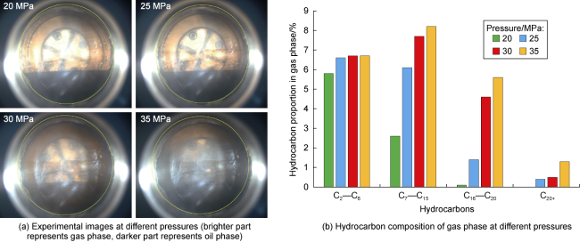
Fig. 2. Experimental results of crude oil extraction by CO2 at different pressures. |
The solubility of CO2 in crude oil increases with pressure [24]. After reaching the minimum miscible pressure, CO2 injection is continued to raise the pressure, and the amount of dissolved CO2 per unit space increases continuously, indicating the amount of CO2 dissolved in the crude oil is linearly and positively correlated with the pressure. Therefore, it can substantially increase the volume coefficient of crude oil, increase the expansion energy, reduce the viscosity of the crude oil, and enhance the flow ability. For terrestrial crude oil in Shengli Oilfield, increasing the pressure from 1.0 times the minimum miscible pressure to 1.2 times the minimum miscible pressure increases the volume coefficient of the crude oil by about 7% and decreases the viscosity by about 17%. In addition, the distribution of marine crude oil components is concentrated in North America; however, the distribution of terrestrial crude oil components in Shengli Oilfield is more dispersed, with more C20-C30 components. So the CO2 can still interact with more heavy components, such as C20+, further improving the recovery after the formation pressure reaches the minimum miscible pressure and continues to increase.
2.2. High pressure expands the lower limit of oil production in micropores, improving flooding efficiency
The minimum miscible pressure test usually adopts the long slim tube method; however, the real reservoir rock structures cannot be reflected because the long slim tube is filled with homogeneous quartz sand. Therefore, the inflection point of the oil displacement efficiency in the long slim tube experiments (corresponding to the minimum miscible pressure) is different from that in the long core experiments. For the cores of marine and terrestrial reservoirs and their corresponding crude oils, 2-m-long core displacement experiments were carried out at different pressures, and the results are shown in Fig. 3a . For marine reservoir experiments, the oil displacement efficiency is 71% at 1.0 times the minimum miscible pressure. Compared with 1.0 times the minimum miscible pressure, the oil displacement efficiency only increases by 2 percentage points at 1.2 times the minimum miscible pressure. For terrestrial reservoirs, the oil displacement efficiency is only 61% at 1.0 times the minimum miscible pressure due to the low permeability, strong heterogeneity, high content of medium and heavy components, and high viscosity of the crude oil. The oil displacement efficiency obviously increases by continuing to increase the pressure, and the oil displacement efficiency reaches 66% at 1.2 times the minimum miscible pressure. The increase in oil displacement efficiency slows down with the rise in pressure, but the obvious inflection point of oil displacement efficiency has not been observed.
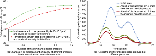
Fig. 3. CO2 flooding efficiency under different pressure levels and T2 spectrum of different-scale pores produced. |
To further analyze the mechanism of CO2 flooding to improve oil recovery in terrestrial reservoirs under ultra-miscible pressure, online NMR CO2 flooding experiments were conducted to study the oil production in different scales of pores at different pressures (Fig. 3b ). When the pressure is 1.0 times the minimum miscible pressure, most oil in the large pores is displaced, while the oil in the small pores is produced to a lesser extent, and the lower limit of pores is 14 nm where oil is displaced by CO2. When the pressure increases to 1.2 times the minimum miscible pressure, the local pressure gradient of the core significantly increases, which is more conducive for CO2 to squeeze into small micropores. The lower limit of pores is broken through to 7 nm, and the available pore volume increases by about 4%. At the same time, the interaction between CO2 and heavy components such as C20+ significantly increases under high pressure, which can more effectively produce heavy components that are difficult to mobilize in large and medium-sized pores. The production percentage of oil in 100-1 000 nm pores is also improved, and thereby the CO2 oil displacement efficiency is improved as well.
2.3. High pressure balances CO2 flooding front, expanding the swept volume
Due to low reservoir permeability and high flow resistance, a large amount of energy is consumed near the bottom of the injection well in terrestrial low-permeability oil reservoirs, and consequently CO2 and crude oil cannot reach a miscible state in the low- pressure area near the production well. The numerical simulation shows that the minimum miscible pressure front and the phase front remain consistent in general miscible flooding (with formation pressure maintained at a level of 1.00-1.05 times the minimum miscible pressure). A sudden change in fluid viscosity occurs before and after the interface of the two front edges (Fig. 4a ). This is because CO2 separates and escapes from the oil phase in the region. The significant difference in viscosity between the gas phase and the oil phase also leads to the fact that CO2 is prone to viscous fingering along the high-permeability channels in the middle and late stages of general miscible flooding. High-pressure miscible flooding usually maintains the reservoir pressure at 1.2-1.4 times the minimum miscible pressure by precisely controlling the injection pressure and injection rate, which can keep the pressure at the displacing front always above the minimum miscible pressure. The miscible phase zone is wide, and the gradient of fluid viscosity change is smaller and continuous (Fig. 4b ). Therefore, high-pressure miscible flooding can effectively make the displacing front evenly developed and eliminate viscous fingering, transforming "finger sweep" into "near spherical sweep" (Fig. 4c -4d ), thus expanding the swept volume and significantly improving the recovery and storage efficiency.
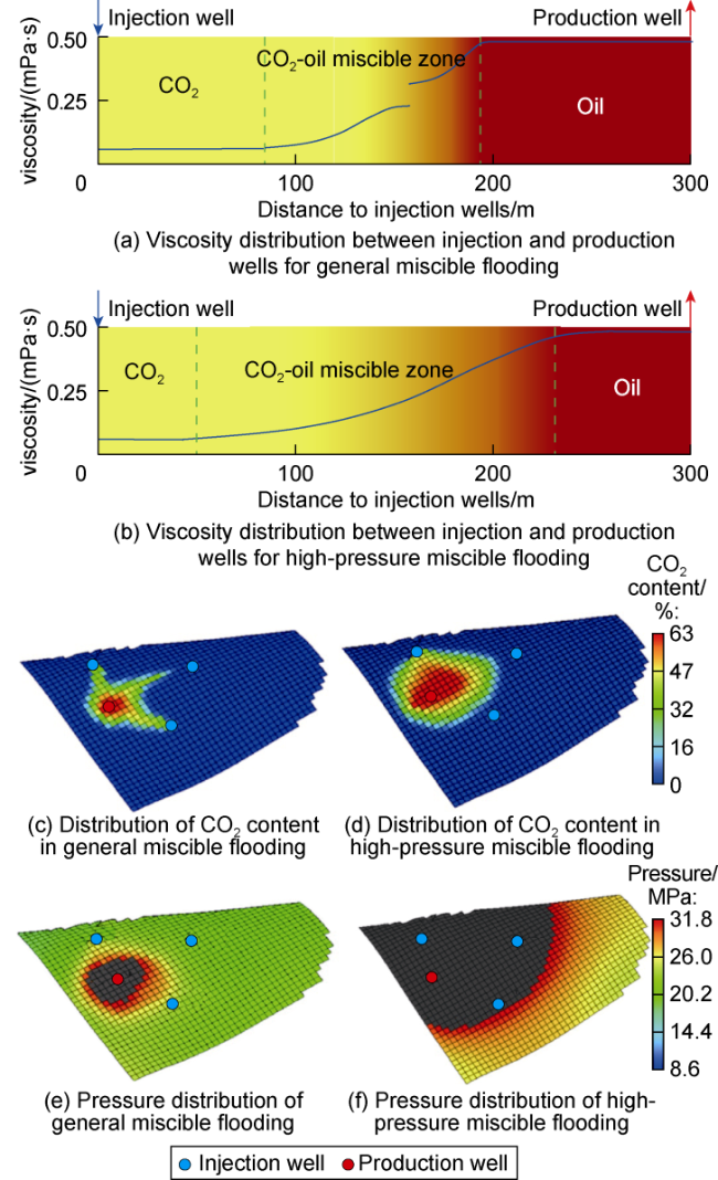
Fig. 4. Simulation comparison of displacing front in general miscible and high-pressure miscible CO2 flooding (gray and black regions in |
3. Key technologies for CO2 high-pressure miscible flooding and storage
Based on the theoretical understanding of CO2 high- pressure miscible flooding and storage, key technologies for CO2 high-pressure miscible flooding and storage have been developed to address issues such as low pressure in terrestrial low-permeability reservoirs, difficulty in increasing the pressure with conventional energy replenishment methods, strong reservoir heterogeneity, and difficulty in dynamic control throughout the whole process.
3.1. High-pressure field reconstruction technology
The pressure of the terrestrial low-permeability reservoir in Shengli Oilfield is low, with an average formation pressure coefficient of 0.68. The water couldn't be injected, and the cost of gas injection for energy replenishment is too high, which makes it difficult to restore formation pressure. Therefore, low-cost and rapid construction of a balanced high-pressure field is a prerequisite for achieving CO2 high-pressure miscible flooding. A physical simulation experimental platform for the whole process of pressure flooding was established, and an experimental study of pressure flooding simulation was carried out on a two-dimensional flat plate model of 50 cm×50 cm×6 cm. The experiment shows that the pore pressure gradually increases through water injection. The injection capacity changes significantly, and stress damage begins to occur in the rock when the injection pressure reaches 52 MPa. Furthermore, the injection capacity rapidly increases when the injection pressure continues to increase to 56 MPa. Through CT scanning, it was found that a microfracture network with an average width of 56 μm generated in the rock plate. According to Fig. 5 , the permeability of the flat plate model is (1-15)×10−3 μm2 before the pressure flooding; however, a network of microfractures generates in the model with significant changes in permeability after the pressure flooding. The permeability of the fracture region is up to 100×10−3 μm2. It can be seen that the permeability of low-permeability reservoirs can be significantly improved by large-displacement water/gas injection under approximate fracturing pressure, so that the reservoir seepage capacity is improved greatly [25], thus providing a basis for the rapid recovery of formation energy in low-permeability reservoirs.
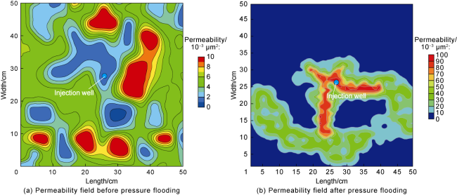
Fig. 5. Permeability field of two-dimensional flat plate model before and after pressure flooding. |
In order to study the pressure transmission during the pressure flooding, a typical model of five-point well pattern with a spacing of 200 m between injection and production wells was established for numerical simulation research. The matrix permeability is 10×10−3 μm2, the conventional injection rate is 20 m3/d, and the pressure flooding injection rate is 1 000 m3/d. Numerical simulation studies show that the pressure flooding can significantly improve the pressure transmission capacity of reservoirs by stimulating their physical properties. Conventional energy replenishment involves continuous point-to-point injection, with long flow paths and high flow resistance outside the main streamline, which makes it difficult to form an effective displacement, resulting in limited swept volume. The pressure flooding forms local high-pressure condition and the microfracture zone shortens the flow path. The oil wells are shut in or produced at low rate to reduce the difference between the main and secondary streamlines, forming a large-scale uniform streamline. As a result, the rapid construction of the high-pressure field in the entire reservoir is achieved (Fig. 6a ). In addition, compared with conventional energy replenishment, the microfracture zone formed by pressure flooding makes the high-pressure zone move forward. The pressure gradient between injection and production wells is greatly increased, which can significantly attenuate the influence of the boundary layer resistance and establish effective injection and production displacement (Fig. 6b ).
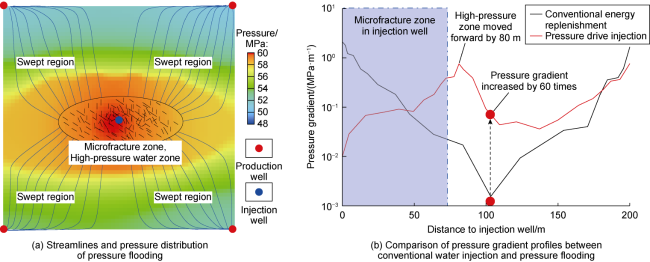
Fig. 6. Pressure transmission during pressure flooding process. |
The technology policy for advanced pressure flooding energy replenishment was established through research. Pre-CO2 slug injection combined with discontinuous pressure flooding is more likely to form a microfracture network rather than a single large fracture. The optimal injection rate is generally 500-1 000 m3/d, and turning to CO2 replenishment after injecting water of 15 000-20 000 m3 can significantly improve replenishment efficiency and reduce replenishment costs. Taking Fan 142-20 block of Zhenglizhuang Oilfield, China as an example, the pressure-drive injection pressure increased by 12 MPa compared with conventional injection pressure. The daily water injection volume of a single well increased from 10 m3 to 500-1 000 m3, and the energy replenishment time was shortened from 2.5 years to 1 month. The formation pressure recovered from 26 MPa to 36 MPa (1.2 times the minimum miscible pressure) and the high-pressure miscible flooding was achieved. The daily oil production increased from 8.2 t to 32.0 t, which shows the remarkable application effect.
3.2. Control technology for the whole process of CO2 flooding and storage
The key to improve recovery and storage factor is to maintain a high-pressure state throughout the whole process and delay gas breakthrough as far as possible after constructing a balanced high-pressure environment through an advanced pressure-drive energy replenishment.
3.2.1. Cascade WAG development technology in the early stage of CO2 flooding
Adding water slugs in the injected gas can effectively increase the flow resistance and delay the breakthrough of CO2 along the high permeability channel. Microscopic visualization experiments show oil phase coalesces into low resistance continuous sheets and moves between the water and gas phases in the form of film in the process of WAG. This "gas driven oil film" process can break the equilibrium of gas displacing oil or water displacing oil in porous media and significantly improve oil displacement efficiency. In addition, the WAG flooding will form a multi-phase displacement phenomenon of oil-gas-oil-water-oil-water, which opens new flow channels through the Jamin effect and blocking effect. This enables CO2 to enter some areas that were previously inaccessible, and enlarges the swept volume. The three-phase flow resistance is constantly changing with the saturation of oil, CO2, and water [26]. A three-phase flow resistance chart of oil, gas and water was drawn through theoretical analysis and experimental research (Fig. 7a ). As development proceeds, the oil saturation continues to decrease and the overall flow resistance decreases. At the same time, the gas-water ratio should be gradually reduced, and the number of slugs per unit space should be increased to maintain a high flow resistance. With the goal of maximizing flow resistance at different development stages, the WAG parameters were optimized throughout the whole process. The gas-water ratio was dynamically adjusted at different development stages to form an optimization chart of the gas- water ratio for reservoirs with different permeability at different development stages (Fig. 7b ). The problems of pressure maintenance and gas breakthrough during the development process have been solved. A cascade WAG flooding was implemented in Gao899 X-4 well group, with the gas-water ratio being adjusted from 2:1 to 1:2. The daily oil production increased from 2.2 t to 17.8 t, and the water cut remained relatively stable. The advantages of WAG in adjusting the streamline and suppressing gas channeling were effectively utilized, and the swept volume was expanded.
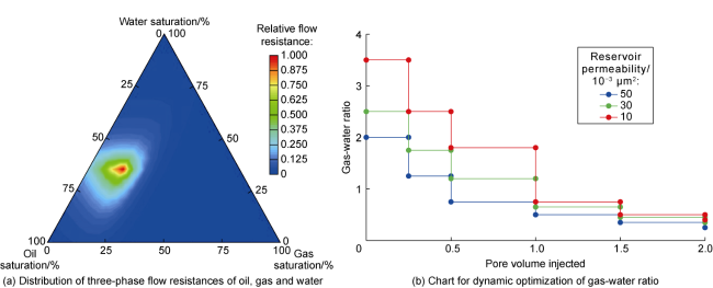
Fig. 7. Diagram of cascade WAG development technology (relative flow resistance is the ratio of flow resistance to maximum flow resistance). |
3.2.2. Injection and production coupling control technology in the middle stage of CO2 flooding
Local gas channeling occurs in the CO2 flooding process due to strong reservoir heterogeneity. By adopting injection and production coupling control technology instead of the traditional continuous injection and production, the direct communication of streamlines between injection and production wells is avoided through the alternating opening of injection and production wells. The high-pressure differential strip is eliminated, resulting in a uniform increase in pressure in the control area of injection and production wells, uniform diffusion of CO2 and fluid diversion. Then, the remaining oil in the corner area is produced sufficiently, and the swept volume is increased [27]. The injection and production coupling is divided into three stages: gas injection, soaking and production (Fig. 8a ). Only injection is carried out without production during the gas injection stage. CO2 is injected at high rate to increase the displacement pressure difference, which drives CO2 towards non-mainstream areas. During the soaking stage, the injection and production wells are shut in simultaneously, the reservoir pressure tends to balance and CO2 gradually dissolves and diffuses from the gas phase into the oil phase. During the production stage, only oil is produced without gas injection. Oil in the non-mainstream areas flows towards the mainstream under pressure difference and is further produced through production wells, and thus volumetric displacement is realized. During this stage, the fluid expansion caused by pressure drop accelerates the production rate, and the swept area of CO2 (including gas-phase CO2 and CO2 dissolved in the oil phase) expands rapidly. The injection and production coupling control technological policies of “short injection, long production, and pressure maintenance” were established through numerical simulation research [28]. This technology has been applied in Gao 89-5 well group. The daily production of the corresponding production well Gao 89-12 has increased from 3.6 t before the treatment to a maximum of 9.0 t (Fig. 8b -8c ).
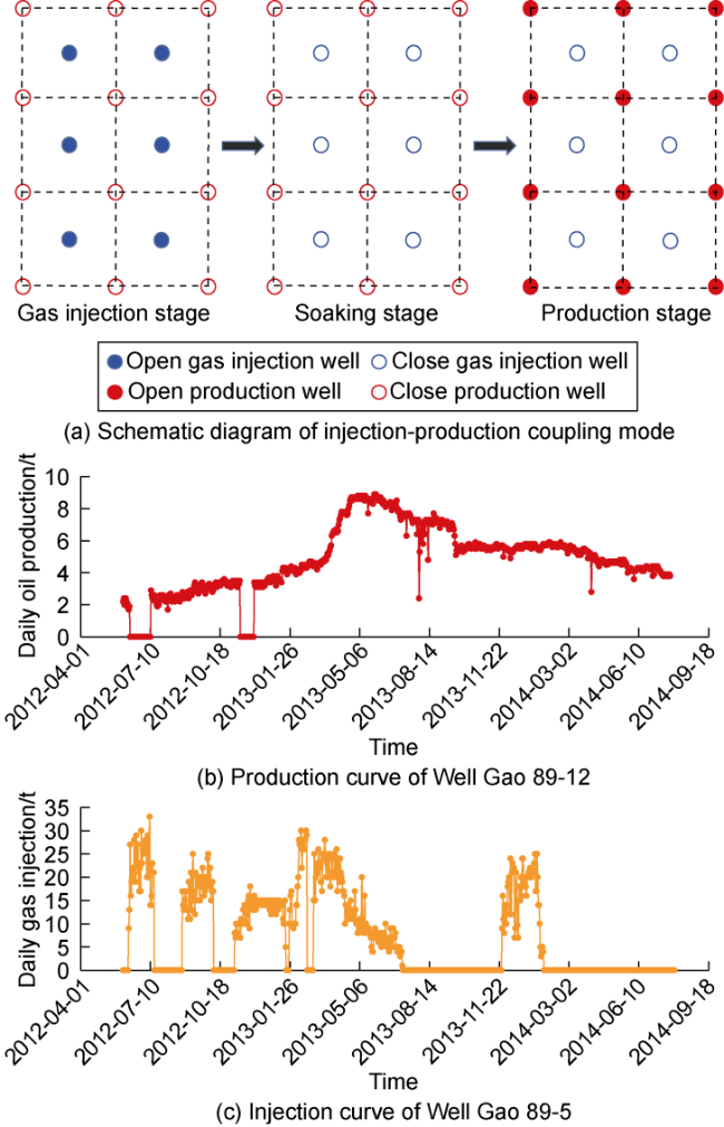
Fig. 8. Injection-production coupling control mode and application results. |
3.2.3. Multi-stage chemical plugging technology in the late stage of CO2 flooding
CO2 flooding front reaches the production well along the high permeability channel in the late stage of CO2 flooding, causing an increase in gas-oil ratio and gas breakthrough in some production wells. Aiming at the gas channeling control in fractures and large pores, an alkyl isopropanol amine surfactant was synthesized by introducing a tertiary amine response group, and salt additives were optimized to construct a CO2-responsive gel system. Alkyl isopropanol amine surfactant is protonated under acid conditions, and the aggregate morphologically changes from spherical micelle to wormlike micelle under the induction of salt additives, thereby crosslinking each other to form a three-dimensional network gel system (Fig. 9a ) [29]. The viscosity of CO2-responsive gel system is less than 3 mPa·s, with good injectivity before injection into formation. But it responds to viscosity increase in gas channels with high gas saturation after injection into the formation. The viscosity can reach over 400 mPa·s, with high-strength plugging properties under the conditions of a temperature of 120 °C and salinity of 10×104 mg/L. The plugging rate for high permeability rock cores with permeability of 2 000× 10−3 μm2 can reach over 80%. In reservoir matrix with high oil saturation, micelles have a solubilization effect on crude oil, resulting in a decrease in system viscosity and minimal reservoir damage. For CO2 channeling caused by interlayer and intralayer heterogeneity in the matrix, CO2-philic carbonyl group is introduced into the hydrophobic tail chain of alkanes with carbon number of 12-16, and the sulfate radical with strong hydration is introduced into the head group to form a temperature resistant and salt resistant CO2 foaming agent. Modified nanoparticles are added to further improve the elasticity of the CO2 foam liquid film (Fig. 9b ). Under the temperature of 120 °C and the salinity of 10×104 mg/L, the system exhibits excellent foaming properties, with a resistance factor of up to 60 and a good plugging effect. This technology has been successfully applied in Gao 89-Fan 142 demonstration area of Shengli Oilfield, with a 100% effective rate. CO2 content in the production well Fan 142-10-2 decreased from 92.5% to 10.1% after the treatment, and the daily oil production increased from 1.1 t to 4.4 t, with an effective period of over 0.5 years.
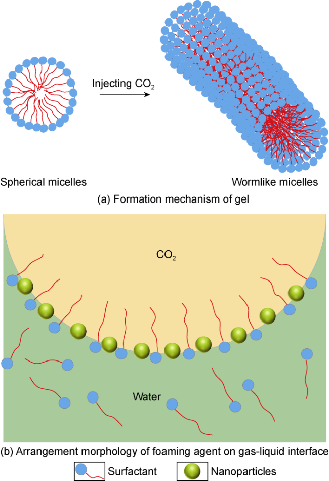
Fig. 9. Schematic mechanism of multi-stage chemical plugging system. |
3.3. Supporting technology
Different from the water injection, the implementation of CO2 flooding and storage faces many challenges in the field, such as high injection pressure, high gas-liquid ratio, strong corrosiveness, and difficulty in disposing of produced gas. After years of technological research, supporting technologies, such as CO2 geological storage safety evaluation technology, safe and efficient injection and production technology, and produced gas recovery and reinjection technology, have been developed.
3.3.1. Safety evaluation technology for CO2 geological storage
The formation pressure during CO2 high-pressure miscible flooding and storage is maintained at a high level, and geological storage safety evaluation is an important technology that ensures the project's smooth operation. The main reason for the security risk of CO2 geological storage is the fluctuation of stress and strain in faults and cap rocks caused by formation pressure change, leading to fault slip, cap-rock rupture, or fracture reopening. The safety evaluation technology for CO2 geological storage includes static and dynamic evaluations for CO2 storage. Based on the geological and mechanical parameters of the cap rocks and faults, the static safety evaluation technology constructs a cap-rock and fault safety evaluation index system to qualitatively evaluate the safety of CO2 storage. The static safety evaluation technology is applied in the field to select storage sites, that is, to select areas with high safety for CO2 flooding and storage. The dynamic safety evaluation technology is used to calculate the CO2 safety limit through simulating the dynamic changes in CO2 migration, formation pressure field and stress field during gas injection and storage.
The key to the dynamic safety evaluation of CO2 storage is the numerical simulation of coupled flow field and stress field, which mainly includes three steps: geological model extension, fluid-solid coupling simulation, and storage safety evaluation. In the process of CO2 flooding and storage, it is necessary to extend the range of the geological model to simulate the overlying, underlying, and surrounding areas of the reservoir since the variation range of stress is larger than the reservoir area, and the error of boundary conditions has an impact on the central area. Then, based on the whole formation geological model, a numerical simulation of CO2 flooding and storage was carried out using the coupled flow field and stress field method. The mass conservation equation of the flow field is:
The rock saturated with fluid can be regarded as a continuous porous medium composed of rock skeleton and fluid, and the stress equilibrium equation is:
where ρ is the average density, expressed as:
According to the effective stress principle, the deformation of rock skeleton is generated by the combined action of external load and pore fluid. The expression of effective stress is:
where p is the average pore fluid pressure, expressed as:
Finally, based on pressure and stress fields obtained by numerical simulation, according to Amonton's law and Anderson's law, the CO2 safe storage pressure is calculated as follows:
In the case of Gao 89-1, the extended geological model of whole formation includes approximately 236×104 grids. The parallel solution algorithm of regional decomposition was adopted due to the large number of grids in the geological model of whole formation, the parameters of flow and stress field in simulation calculations, and high calculation dimension. Based on the high-performance computing platform built by the Beijing Super Cloud Computing Center, the pressure field, component field and stress field during CO2 flooding and storage were simulated, and the vertical stress and minimum horizontal principal stress of the reservoir and the normal stress and tangential stress of the fault were calculated. The fault friction coefficient was calculated through Eq. (6). At last, the pressure for the safe storage in Gao 89-1 was calculated to be 36 MPa through Eq. (7).
3.3.2. Safe and efficient injection and production technology
Since the gas sealing pressure level of traditional gas injection packers is low, it is easy for supercritical CO2 to leak at the packers, causing an increase in casing pressure and posing safety risks to the operation and management of gas injection wells. A high-pressure safe injection string (Fig. 10a ) was developed. The material of the rubber cylinder and the sealing structure of the packer were optimized. A masterbatch with excellent CO2 barrier properties was used for the rubber cylinder, and a high-temperature resistant rubber material was prepared with a multifunctional compound as the crosslinking center. The bidirectional compression and continuous loading sealing concept was introduced to improve the sealing capacity and pressure bearing capacity of the packer. A high-pressure gas sealing packer was developed to solve the problem of gas sealing under high-pressure conditions. The gas sealing pressure difference of the injection string reaches 50 MPa [8,30 -31]. Corrosion is a major cause of tubing perforation failure in acidic CO2 environments. A supplementary technology for corrosion prevention was developed, mainly using corrosion inhibitors and supplemented with corrosion-resistant materials. A high gas-liquid ratio anti-corrosion lifting string (Fig. 10b ) was also developed, which slows down string corrosion by regularly adding solid corrosion inhibitors and continuously dripping liquid corrosion inhibitors. A sacrificial anode was adopted in the pump body to achieve anti-corrosion. Gas-liquid pump was adopted to achieve high gas-liquid ratio and efficient lifting, effectively controlling the corrosion rate of the downhole strings and meeting the lifting and anti-corrosion requirements of the wells with high water cut and gas-oil ratio.
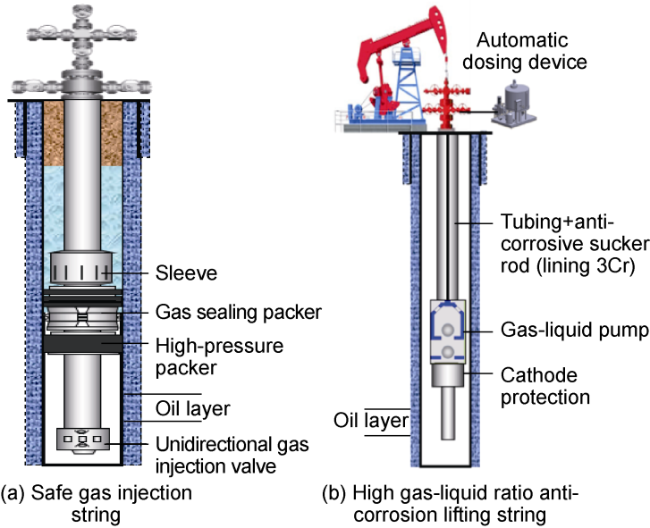
Fig. 10. Safe and efficient injection and production strings. |
3.3.3. Produced gas recovery and reinjection technology
With the implementation of CO2 flooding, CO2 gradually breaks through the production wells. A large amount of mixed gas composed of light hydrocarbons and CO2 will be produced when the pressure drops sharply. Efficient and low-cost recovery and reinjection of produced gas can reduce resource waste and improve CO2 storage factor. A series of produced gas recovery and reinjection technologies suitable for different development stages were developed: A three-phase separator was used to separate and remove free gas, with a removal rate of 90.3%. The process of "thermochemical sedimentation dehydration + micro-positive pressure closed decarbonization" was adopted to separate the produced oil, and CO2 content in the separated oil was less than 1 000 mg/L. The gas extraction decarbonization technology was used to separate the produced water, and the CO2 content in the separated water was less than 50 mg/L. Long core displacement experiments were conducted on produced gas with different CO2 contents. The experimental results show that the oil displacement efficiency increases with the increase of CO2 content when the CO2 content in the produced gas is less than 73%. At the same time, the produced gas should be liquefied and purified by distillation before reinjection. The impact of CO2 content on oil displacement efficiency is relatively small when the CO2 content in the produced gas is higher than 73%. The produced gas can be directly compressed and injected through a reinjection compressor. The process is shown in Fig. 11 . At present, this technology has been fully applied in Gao 89-Fan 142 demonstration area, achieving near zero emissions of injected CO2.
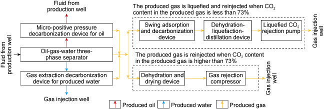
Fig. 11. Process of produced gas recovery and reinjection. |
4. Field applications
In 2013, Shengli Oilfield conducted a CO2 high-pressure miscible flooding pilot test in Fan 142-7-X4 well group. Based on this, it has accumulated experience and verified the correctness and feasibility of the relevant theories and technologies. In 2022, the technologies were applied in Gao 89-Fan 142 demonstration area in a large scale, achieving remarkable development results.
4.1. Pilot test of high-pressure miscible flooding in Fan 142-7 -X4 well group
Fan 142-7-X4 well group is located in the northern part of Fan 142-10 unit of the Zhenglizhuang Oilfield. The main oil layer is the Lower Chunhua Submember of the Fourth Member of the Paleogene Eocene Shahejie Formation, whose burial depth ranges from 2 800 m to 3 200 m. The average permeability of the well group is 1.2×10⁻³ μm2. The bar sandstone in the east and the beach sandstone in the west are developed. The minimum miscible pressure is 31.6 MPa. The well group was put into elastic production through fracturing, the formation pressure decreased from the original pressure of 42.6 MPa to 17.1 MPa, and the average daily oil production was less than 1 t per well at the initial stage.
The pilot test for CO2 high-pressure miscible flooding was designed in an inverted seven-point well pattern composed of 1 injection well and 6 production wells with injection and production well spacing ranging from 240 m to 670 m (Fig. 12a ). CO2 was injected continuously, and the reservoir pressure was maintained at 1.2 times the minimum miscible pressure. The development was divided into three stages: pressure recovery, pre-production and gas flooding. To accurately assess the recovery of formation pressure, all production wells were equipped with memory electronic pressure gauges for bottom-hole pressure monitoring. The pressure monitoring data was used as the basis for determining whether CO2-oil was miscible and whether production well should be opened for production. The pilot test started injecting CO2 in June 2013. A total of 1.9×10⁴ t of CO2 had been injected up to November 2016. Pressure monitoring data showed that the formation pressure in the eastern well group recovered from 17.1 MPa before gas injection to 40 MPa, reaching 1.2 times the minimum miscible pressure and realizing the full range of high-pressure miscibility. Since November 2016, all three wells in the eastern region have achieved flow production, with an initial daily oil production of 6-9 t per well and a stable production of over 5 t for more than two years at the later stage (Fig. 12b ).
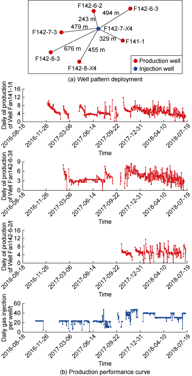
Fig. 12. Pilot test in Fan 142-7 -X4 well group. |
4.2. CO2 high-pressure miscible flooding and storage project in Gao 89-Fan 142 demonstration area
Gao 89-Fan 142 demonstration area is located in the northern part of Zhenglizhuang Oilfield. The oil layers are the 1-4 sandstone groups of the Lower Chunhua Submember of the Fourth Member of the Paleogene Eocene Shahejie Formation with a burial depth of 2 800 m to 3 200 m. It is a beach-bar sandstone reservoir with a permeability of 2.1×10⁻³ μm2. The in-place oil viscosity is 1.59 mPa·s, the average minimum miscible pressure of in-place oil is 30 MPa. The original formation pressure is 41.8 MPa, and the pressure coefficient is 1.42. After long-term elastic development, the average daily oil production per well was 1.9 t, the oil recovery rate was 0.3%, and the recovery was 8%. The average formation pressure was 22 MPa, only 0.55 times the minimum miscible pressure. It was classified as a typical block with low oil recovery rate, recovery and pressure maintenance level, and was in urgent need of a new development mode to improve its production capacity and recovery.
Drawing on the successful experience of the CO2 high-pressure miscible flooding pilot test in Fan 142-7-X4 well group, a CO2 high-pressure miscible flooding and storage engineering plan for Gao 89-Fan 142 demonstration area was developed. This plan includes 73 injection wells and 166 oil wells in an irregular well pattern with injection and production well spacing of 400 m. The formation pressure was designed as 1.2 times the minimum miscible pressure and WAG was used as injection method. The plan was expected to increase the oil recovery by 11.6 percentage points within 15 years, with an oil exchange ratio of 0.3 (0.3 t of oil could be produced for every 1 t of CO2 injected).
To ensure the safety of CO2 storage, a three-level (high, medium and low risk), three-dimension (air, surface and underground), and three-medium (gas, liquid and solid) environmental monitoring system was constructed. In terms of time, two periods were considered: the construction period and the operation period. CO2 background values were obtained during the construction period; the change trend of CO2 concentration and flux in the demonstration area was obtained during the operation period, providing data support for subsequent ecological assessment and storage capacity accounting. In terms of the space, monitoring of near surface, air, soil air, shallow groundwater and deep groundwater were considered. CO2 migration pathways were mastered in the demonstration area, and CO2 leaks were early warned and detected in small areas such as key facilities and sensitive points, providing technical assistance for taking engineering measures.
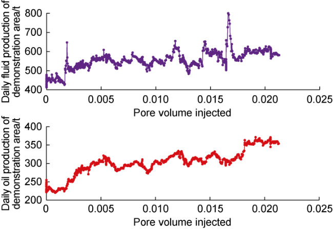
Since June 2021, pressure-drive water injection has been completed 67 well times, with a cumulative water injection volume of 110.0×10⁴ m3. In April 2022, gas injection began at a daily injection of 1 500-1 800 t. As of May 2024, the average dynamic liquid level in the demonstration area had risen by 78 m. The formation pressure had recovered to over 32 MPa with an increase of 9.6 MPa, reaching a miscible phase state. The daily oil production had increased from 254.6 t to 358.2 t (Fig. 13 ). It showed a continuous upward trend and stable water cut without obvious gas channeling, which demonstrated good development effect. Environmental monitoring was conducted over 10 000 times, and the monitoring results were consistent with the background values without any abnormalities, indicating safe storage.
Fig. 13. Development performance of Gao 89-Fan 142 demonstration area. |
5. Conclusions
To address the challenges of difficult miscible phase and poor development effect by conventional development methods in CO2 flooding reservoirs of Shengli Oilfield, a CO2 high-pressure miscible flooding and storage theory suitable for terrestrial reservoirs in China has been developed through laboratory experimental studies. The miscible ability of medium and heavy components in crude oil was enhanced and the production percentage of crude oil in small pores was increased by significantly increasing the reservoir pressure to 1.2 times the minimum miscible pressure, and the swept volume was expanded by balancing the displacement front, so that a significant increase in the oil recovery and CO2 storage factory was realized.
To cope with the difficulties of low initial reservoir pressure level, strong heterogeneity and easy gas channeling in the process of CO2 flooding, the advanced pressure flooding energy replenishment technology was applied to construct a balanced high-pressure field quickly, cascade WAG was carried out for flooding control, and the whole process control methods, such as injection and production coupling and multi-stage plugging were used to adjust the flow field dynamically and continuously, achieving the collaborative optimization of oil recovery and CO2 storage factor. The geological safety evaluation technology for CO2 storage was established to ensure the long-term storage safety and stability of the target area. What's more, supporting technology provides guarantees for the efficient and safe implementation of CO2 high-pressure miscible flooding and storage.
The pilot test of Fan 142-7-X4 well group in Shengli Oilfield achieved high-pressure miscibility in the full range. The daily oil production of a single well increased from 1 t to over 5 t, with a stable production time of more than 2 years, verifying the correctness and feasibility of the theories and technologies. On this basis, it has been applied to Gao 89-Fan 142 CCUS demonstration area, which has currently reached a high-pressure miscible state. The daily oil production in the block increased from 254.6 t to 358.2 t, showing a continuous upward trend, with no obvious gas breakthrough and no abnormal environmental monitoring. It has achieved efficient development of CO2 flooding and storage in low-permeability reservoirs, providing theoretical and technical support for the large-scale application of CCUS in China.
Nomenclature
B—Biot coefficient;
Cα,o, Cα,g, Cα,w—mass fraction of component α in oil phase, gas phase, and water phase, %;
F—the sum of the component α in each phase, kg/(m2·s);
g—gravity acceleration, m/s2;
p—average pore fluid pressure, Pa;
po, pg, pw—pressure of oil, gas, and water phases in pores, Pa;
q—volume source and sink term, kg/(m3·s);
So, Sg, Sw—saturation of oil phase, gas phase, and water phase, %;
t—time;
T2—transverse relaxation time, ms;
δ—Kronecker symbol;
μ—fault friction coefficient, dimensionless;
ρ—average density, kg/m3;
ρo, ρg, ρw—density of oil phase, gas phase, and water phase, kg/m3;
ρs—rock density, kg/m3;
σ—stress, Pa;
σ'—effective stress, Pa;
σc—Cauchy stress tensor, Pa;
σh—minimum horizontal principal stress, Pa;
σn—normal stress of fault, Pa;
σv—vertical stress, Pa;
τ—tangential stress of fault, Pa;
ϕ—porosity, %.