

Introduction
In the 1990s, the Daqing and Shengli oil fields in China were the first to achieve the industrial application of polymer flooding in high-water cut blocks. In 2003, the Bohai Oilfield began implementing offshore polymer flooding pilot tests. After decades of technological updating and iteration, some key chemical flooding technologies with polymer as the main agent such as surfactant-polymer binary flooding, alkali-surfactant-polymer flooding, and heterogeneous composite flooding have been developed [1-2]. Traditional polymer flooding is limited by easy shear degradation, difficult injection, and low-efficiency cycles [3⇓-5]: The molecular chain of conventional polymers is prone to shear fracture during the injection process, especially in offshore reservoirs by polymer flooding, which requires high injection speeds due to the large spacing between wells, leading to a polymer viscosity loss of over 50% after passing through perforations and near-well zones [6]. In the medium to low permeability reservoirs with small pore throat sizes, the implementation of polymer flooding results in additional flow resistance due to the gyration radius of the polymer molecular, resulting in a sharp increase in injection pressure. Furthermore, during polymer flooding in highly heterogeneous, high-water-cut oil reservoirs, the polymer solution tends to preferentially enter high-permeability layers, resulting in channeling and inefficient circulation. These issues severely affect the production enhancement and economic benefits of polymer flooding, highlighting the need to explore new chemical flooding methods to improve oil recovery.
The concept of capsules can be traced back to the pharmaceutical capsules of the medical field. Taking enteric coated capsules as an example, by incorporating special materials into the capsule shell, they are designed not to dissolve in gastric fluid but only start to melt in the alkaline fluid of the intestines, achieving targeted drug delivery [7]. In recent years, capsule technology has gradually been applied in the field of oil and gas development, mainly for processes such as profile control water plugging, and acidizing fracturing. The capsules used include surfactants, gels, acidizing acids, and other types [8]. Drawing on previous research, we proposed a method to enhance oil recovery using capsule polymer flooding and independently developed capsule polymers. Micro- and nano-scale capsules are formed by encapsulating high molecular weight polymers within a shell layer, and then they can be injected into the reservoir. Under reservoir temperature and salinity conditions, the triggered release of polymers achieves targeted viscosity enhancement, effectively reducing chemical agent loss, and improving the effectiveness of polymer flooding. On this basis, the properties of capsule polymer were characterized and evaluated, the reservoir numerical simulation and effect analysis were carried out, and the flow mechanism and oil displacement mechanism of capsule polymer flooding were explained, to provide a new idea and method for enhancing oil recovery by chemical flooding.
1. Capsule polymer flooding for enhanced oil recovery
1.1. Idea of capsule polymer flooding to improve oil recovery
The purpose of capsule polymer flooding is to break the traditional concept of polymer flooding, change from viscosity enhancement ground to viscosity enhancement in the deep reservoir, and achieve enhanced oil recovery. The basic idea is to synthesize micro- and nano-scale capsule polymer emulsion systems on the ground, drawing inspiration from enteric-coated capsules. When injected, the polymer is encapsulated by the capsules, maintaining the capsule form and keeping the polymer molecular chains in a bound state without exerting viscosity-enhancing effects at the ground and near-well zones. In the process of moving to the deep reservoir, the capsules gradually rupture under the influence of external factors such as reservoir temperature and salinity, releasing the polymer to realize viscosity enhancement and ultimately enhance oil recovery.
The capsule polymer has time-varying characteristics when it flows in the reservoir (Fig. 1 ): (1) Near the well bore, the polymer is protected by the capsule shell, providing strong shear resistance; (2) In the near-well zones, the capsule particles can achieve temporary plugging and deformation migration; (3) In the middle zone of the reservoir, the capsule shell gradually ruptures under reservoir conditions, allowing controlled release of encapsulated polymers; (4) In the deep reservoir zones, the polymer molecular chains fully extend to achieve targeted viscosity enhancement of the displacing fluid. For highly heterogeneous and high-permeability reservoirs, the capsule size shall be reasonably designed based on applicable injectivity to give play to flooding control and reduce the inefficient circulation of injected fluid.
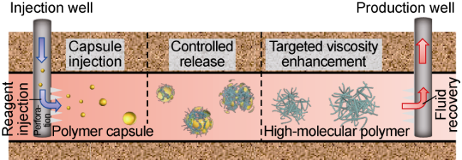
Fig. 1. Schematic flow process of capsule polymer flooding. |
1.2. Synthesis and characterization of the capsule polymer
The capsule polymer emulsion was prepared using temperature-resistant, salt-resistant polymer as the core material and polyurethane as the shell material, employing a method of “inverse emulsion polymerization + re-emulsification + interfacial polycondensation” [9]. The effective solid content of the capsule polymer emulsion is 37%. The particle size of the capsules ranges from 100 nm to 1 500 nm, with a median particle size of 440 nm. The microstructure of the capsule polymer was observed by transmission electron microscopy (TEM, Tecnai G20) (Fig. 2a ). It is shown that the capsule polymer has a distinct core-shell structure. The darker regions in the images correspond to the polymer core, while the brighter areas represent the polyurethane shell. Additionally, scanning electron microscopy (SEM, Thermo Apreo S) was employed to examine the three-dimensional structure and micromorphology of the capsule particles (Fig. 2b ), showing that the capsules exhibit smooth spherical surfaces.

Fig. 2. Micromorphology image of capsule polymer. |
Nanoindentation experiments on the capsule polymer were conducted using atomic force microscopy (AFM, Bruker Multimode-8). A solution with a mass concentration of 50 mg/L was dropped onto a clean mica sheet to measure the displacement of the probe and the applied force (Fig. 3 ). The results were fitted and analyzed using the Snedden model, yielding an elastic modulus of 7.72 GPa for the capsules [10]. This indicates that the capsule polymer exhibits rigid particle behavior at room temperature, making it difficult to deform under external forces, thereby demonstrating significant stability.
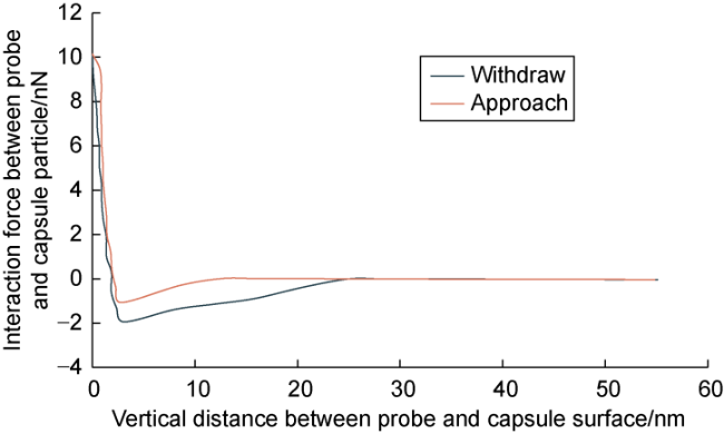
Fig. 3. Force-distance curve of capsule polymer in nanoindentation experiment. |
1.3. Rupture mechanism and rheological properties of capsule polymer
Under reservoir temperature and salinity conditions, the properties of the capsule polymer shell will change. The differential scanning calorimeter (DSC) curve of the capsule polymer was obtained using DSC STA449F5 Jupiter (Fig. 4 ). The results indicate a distinct endothermic process between 48.46 °C and 52.41 °C, during which the capsule shell remains undegraded and corresponds to the glass transition temperature range, with a glass transition temperature of 50.44 °C. When high polymers undergo glass transition, the elastic modulus significantly decreases, suggesting that under reservoir temperature conditions, the capsules transition from a rigid to a flexible state, making them more susceptible to deformation during the flow process [11]. Due to the influence of external factors such as reservoir temperature and salinity, the physical structure and mechanical properties of the shell layer changes, and then cracks appear in the shell, or its permeability becomes stronger. Formation water gradually enters the inside of the capsule polymer, and the internal polymer swells when it meets water, which further destroys the shell layer and releases the polymer.
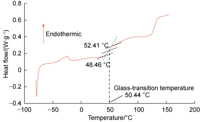
Fig. 4. Capsule polymer DSC curve. |
Further observation of the microscopic images (Fig. 5 ) and analysis of the changes in the capsule polymer shell layer and core during the triggering process indicates that in the early stage of aging, under the influence of temperature and salt ions, the capsule polymer shell layer begins to roughen (Fig. 5a ). At this point, the mechanical properties of the shell layer gradually change, leading to deformation and wrinkling of the shell under hydrodynamic or other forces (Fig. 5b ). Upon water entering into the capsule, polymer swelling occurs, resulting in capsule rupture (Fig. 5c ). Then, the polymer is released and the molecular chains gradually extend. The network structure of the released polymer could be observed in the cryo-scanning electron microscope images (Fig. 5d ).
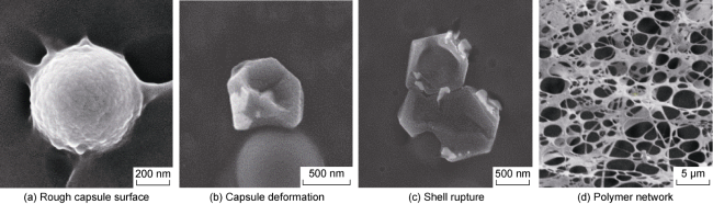
Fig. 5. SEM images of capsule polymer at different viscosity-increasing stages. |
Water with a salinity of 10 000 mg/L (prepared with NaCl) was mixed with a capsule polymer solution with a mass concentration of 2 000 mg/L. The mixture was deoxygenated under vacuum and sealed in an ampoule [12]. Thermal aging experiments were conducted at temperatures of 75, 85 and 95 °C. A rheometer (Anton Paar MCR 302) was used at 75 °C to determine the viscosity changes of capsule polymer solution with aging time at different aging temperatures (Fig. 6 ). The results are as follows: (1) The time required for thickening of the product varies with aging temperature; higher aging temperatures result in shorter thickening times. In the experimental temperature range, the release time of the polymer is about 3 d to 8 d. (2) When the aging temperature is 75 °C, the viscosity increase curve of the solution shows three stages: slow rise, fast rise and reaching stability. When the aging temperature is 85-95 °C, the solution viscosity increase curve only exhibits the latter two stages. (3) Comparing the viscosity increase curves at the three aging temperature conditions, it is evident that higher temperatures lead to faster thickening, but the final viscosity stabilizes around 53 mPa·s in all cases at the test temperature of 75 °C.
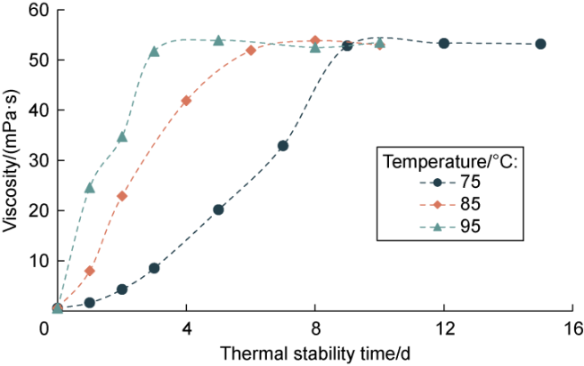
Fig. 6. Effect of aging temperature on viscosity curve of capsule polymer. |
Additionally, water with a salinity of 20 000 and 35 000 mg/L was mixed with the capsule polymer solution with a mass concentration of 2 000 mg/L, and the thermal aging experiment was carried out at 85 °C according to the above method. Subsequently, a rheometer was used to determine the viscosity changes of capsule polymer solution with aging time under different salinity conditions at 75 °C test temperature (Fig. 7 , which includes the data from the previous 10 000 mg/L salinity condition at 85 °C aging temperature). The findings indicate that: (1) As aging time extends, the viscosity of the solution rises rapidly and eventually stabilizes. (2) Higher salinity results in lower viscosity of the solution after capsule polymer releases. (3) In the experimental salinity range, the polymer release time was about 6 d, indicating that the salinity has little effect on the viscosity-increasing rate of the capsule polymer solution.
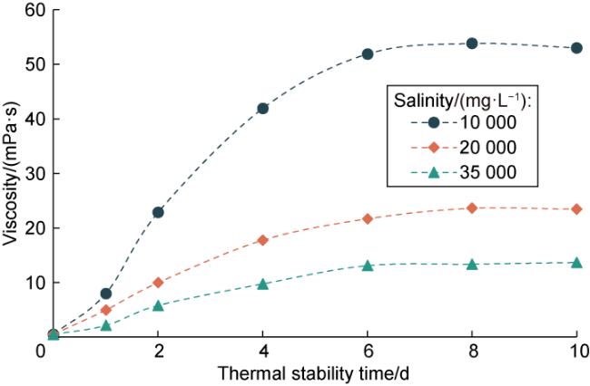
Fig. 7. Influence of salinity on viscosity curve of capsule polymer. |
In summary, temperature primarily influences the rate of viscosity increase in the capsule polymer solution, while salinity has a minor effect. It is necessary to optimize the formula of the capsule polymer flooding agent according to reservoir conditions to realize deep reservoir profile control and targeted viscosity increase during actual oilfield development.
The suction-spray process of homogenizer (Polytron PT 2500E) was adopted to simulate the high-speed shear process of fluid at the wellbore perforation [13], and the viscosity retention rate of the solution at different shear rates could be measured (Fig. 8 ). The viscosity of conventional polymer solutions was measured immediately after shearing, while the viscosity of the capsule polymer solution was measured when it had fully thickened after shearing and aging. The results indicate that at a rotational speed of 12 000 r/min, the viscosity retention rate of the conventional polymer is only 36.7%, whereas the viscosity retention rate of the capsule polymer solution exceeds 98%. This demonstrates that the capsule polymer solution possesses excellent shear resistance.
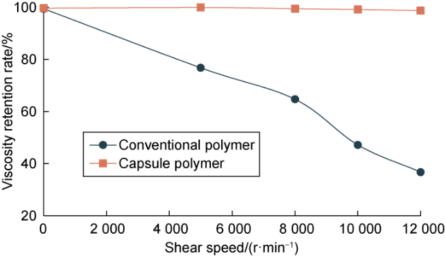
Fig. 8. Comparison of shear resistance between conventional polymer and capsule polymer. |
2. Flow mechanism and oil displacement mechanism of capsule polymer flooding
2.1. Flow mechanism and oil displacement mechanism at pore throat scale
Flow and oil displacement experiments were conducted using water with a salinity of 20 000 mg/L and calcium and magnesium ion concentrations of 412 mg/L and 102 mg/L, respectively. The mass concentration of the capsule polymer solution was maintained at 2 000 mg/L.
The flow behavior of the capsule polymer solution passing through a pore throat at different degrees of thickening (the ratio of viscosity at various aging times to viscosity after complete release) was measured using the Dantec micro-particle image velocimetry (PIV) system. The microfluidic chip used was made of polymethyl methacrylate (PMMA) material with a single pore throat, 200 μm in-depth, a pore channel width of 500 μm, a throat width of 100 μm, and a throat length of 400 μm. The capsule polymer solution was injected into the chip at the rate of 15 μL/min after being aged in the incubator of the ampoule for different time intervals. Based on the flow field analysis results (Fig. 9 ), it can be concluded that: (1) The flow velocity of the unthickened capsule polymer solution is the highest at the throat, and as the thickening degree increases, the high-velocity region gradually expands towards the entrance and exit of the throat. (2) With increasing thickening degree, the fluid elasticity strengthens. When the thickening degree reaches 60%, obvious vortices begin to appear at the pore corners, which is conducive to tap the potential of the remaining oil in blind ends and corners of porous media during the oil displacement process [14].
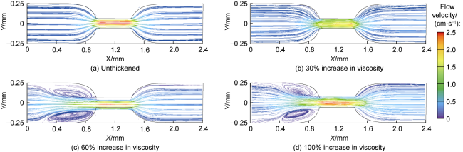
Fig. 9. Flow field distribution of capsule polymer solution at different thickening degrees. |
The micro-scale oil displacement experiments utilized a two-dimensional etched model with dimensions of 2.5 cm×2.5 cm, featuring pore throats approximately 200 μm to 300 μm in size and an etching depth of 60 μm. The model was saturated with crude oil having a viscosity of 50 mPa·s, and then aged for 6 h, with an initial oil saturation of 96.7%. Different displacing phase fluids were injected at a rate of 5 μL/min to capture fluid distribution images under varying thickening degrees and injection volumes (Fig. 10 ). The experimental results indicate that: (1) Under the same injection volume, the higher the thickening degree of the capsule polymer solution, the larger the swept range of displacement phase, and the more uniform the displacement front tends to be. This is attributed to the increase in displacing phase viscosity, which reduces the oil-water viscosity ratio and effectively suppresses the occurrence of viscous fingering. (2) There is little difference between the oil displacement effect of unthickened solution and water displacement. Still, the presence of capsule particles slightly enhances the oil recovery efficiency of the unthickened solution. (3) When the water cut reaches 98%, the ultimate oil recovery factor achieved by the fully thickened capsule polymer is 76.8%, representing an increase of 24.0 percentage points compared with water flooding recovery factor.
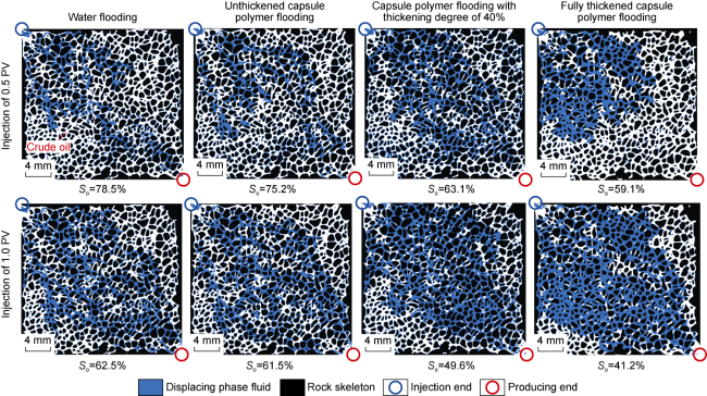
Fig. 10. Fluid distribution at the end of displacement under different thickening degrees and injection volumes. |
Utilizing a high-temperature and high-pressure visualization oil displacement experimental platform, the study further simulated the enhanced viscosity behavior and displacement performance of the capsule polymer solution under reservoir conditions. An etched model with dimensions of 4.5 cm×4.5 cm, throat diameters ranging from 20 μm to 80 μm, and an etching depth of 50 μm was placed inside a high-pressure vessel. The experimental temperature was set at 75 °C with a confining pressure of 15 MPa. The model was saturated with crude oil of viscosity 28.6 mPa·s, and aged for 24 h. Subsequently, the 0.5 PV (pore volume) of unthickened capsule polymer solution was injected at a rate of 0.002 mL/min and aged for 10 d, followed by injection of 1.0 PV of simulated formation water. Different colors were used to distinguish the displacing phase and the crude oil, resulting in microscopic images of the oil displacement by the capsule polymer (Fig. 11 ). The image analysis reveals that initially, due to the short injection time, the capsule polymer was not fully released, resulting in relatively low viscosity. The injected fluid primarily formed preferential channels along the diagonals with a limited sweep area. As the aging time increased, more capsule polymers gradually released, leading to an increase in viscosity. This increased the flow resistance along the diagonal channels. Upon subsequent water injection, the injected water branched out, with some water displacing slowly along the diagonal channels, but the other part of the water flows around the dominant channel. This resulted in a significant expansion of the sweep area, with the sweep efficiency increasing from 42.9% to 77.2%.
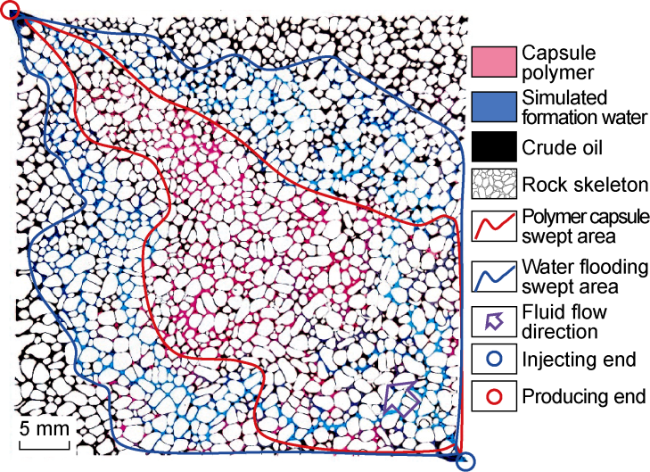
Fig. 11. In-situ viscosity-increasing and microscopic oil displacement experiment of capsule polymer flooding. |
2.2. Core-scale flow mechanism and oil displacement mechanism
Single-tube core flooding experiments were conducted to study the injection performance and permeability applicability limits of the capsule polymer. Four single-tube cores of identical dimensions (diameter of 2.5 cm, length of 10 cm) were selected, with permeabilities of 10×10−3, 30×10−3, 50×10−3, and 130×10−3 μm2, respectively. The capsule polymer solution used in the experiments had a mass concentration of 2 000 mg/L. The fluid injection rate was controlled at 0.5 mL/min, and the flooding experiment was carried out in three steps: water flooding, capsule polymer flooding, and subsequent water flooding. The changes in injection pressure of the capsule polymer solution in cores with different permeabilities were recorded (Fig. 12 ). From the figure, it can be observed that the difference between the injection pressure of the capsule polymer solution and the water injection pressure is negatively correlated with permeability. Higher core permeability results in a lower pressure difference, making the injection of the capsule polymer solution easier. With a core permeability of 10×10−3 μm2, the injection pressure increases significantly when injecting the capsule polymer solution. This is due to the smaller pore radius of low-permeability cores, where the size of the capsule polymer is close to that of the core throat. The interactions between the capsules, between the capsules and the fluid, and between the capsules and the rock surface are significant, leading to pronounced discontinuous phase flow characteristics and resulting in additional flow resistance [15]. The resistance factor, defined as the ratio of the injection pressure of the capsule polymer to the water injection pressure was calculated. The results indicate that when the core permeability exceeds 30×10−3 μm2, the resistance factor for capsule polymer flooding is relatively low (smaller than 2), making it suitable for implementing capsule polymer flooding. However, below this permeability threshold, injection issues may arise. Using the same procedure as the core flooding experiments, the dynamic adsorption characteristics of the capsule polymer were tested. The dynamic adsorption rate of the capsule polymer in a core with a permeability of 170×10−3 μm2 was found to be 0.018 mg/g, confirming that the capsule polymer has a low adsorption retention rate and exhibits good mobility in deep reservoirs.
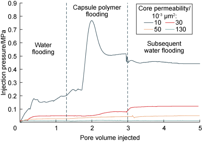
Fig. 12. Change curve of injection pressure of unthickened capsule polymer. |
To evaluate the resistance enhancement capability of the capsule polymer after its release in the deep reservoir, four cores with permeabilities of 30×10−3, 75×10−3, 130×10−3 and 560×10−3 μm2 were selected. The fully thickened capsule polymer solution was injected using the same approach as in the injection performance evaluation, and the injection pressure curves are shown in Fig. 13 . Calculations reveal that the resistance factor of the un-thickened capsule polymer solution is 2 at most, while the resistance factor of the fully thickened solution ranges from 25 to 32. This significant increase in the resistance factor indicates that the thickened capsule polymer solution provides excellent viscosity and resistance enhancement in the deep reservoir compared with the unthickened solution. During the subsequent water flooding phase, the injection pressure rapidly decreases. This is primarily because the relatively high-permeability regions occupied by polymers in the core present lower flow resistance, allowing the polymer to be quickly displaced by the following injection of water, thereby re-forming preferential flow pathways. In medium- to low-permeability cores, the regions occupied by polymers still exhibit considerable flow resistance, making it difficult for the subsequent water injection to completely displace the polymer. Therefore, the resistance enhancement effect can persist for a certain period, with the residual resistance factor (the ratio of pressure during the subsequent water flooding phase to the water injection pressure) ranging from 5 to 12.
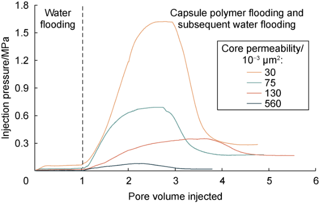
Fig. 13. Change curve of injection pressure of capsule polymer after fully thickening. |
Further investigations into the oil displacement effect of the capsule polymer were conducted using a dual-core flooding experiment. Two cores with permeabilities of 300×10−3 μm2 and 75×10−3 μm2 were connected in parallel. The experimental conditions were set at a temperature of 75 °C. It was saturated with crude oil having a viscosity of 230 mPa·s, and aged for 24 h. Then, water was injected at a rate of 0.5 mL/min until a water cut of 98% was reached. After injecting 0.4 PV of the fully thickened capsule polymer solution, subsequent water flooding was performed. The injection pressure curves, split ratio curves, and enhanced recovery results of high-permeability and low-permeability cores are shown in Fig. 14 . The results are as follows: (1) During the water flooding phase, the injection pressure gradually increased, followed by a decline once a breakthrough occurred. The recovery degree from the high-permeability core was 49.5%, while that of the low-permeability core was 8.0%. (2) In the capsule polymer flooding phase, the injection pressure rose again and finally exceeded that in the water flooding stage due to the viscosity-enhancing effect of the polymer. The split ratio of high permeability core decreased rapidly, and the oil content in the produced fluid increased. For the low-permeability core, the split ratio increased rapidly from 2.4% to a maximum of 48.7%. (3) In the subsequent water flooding phase, the injection pressure began to decline. Compared with the capsule polymer flooding phase, the split ratio in the high-permeability core increased, while the split ratio in the low-permeability core decreased. However, the average split ratio decreased from 9.5:1.0 during water flooding to 7.0:3.0. (4) The ultimate recovery factor from the high-permeability core was 78.5%, showing an increase of 29 percentage points compared with the water flooding phase. The ultimate recovery factor from the low-permeability core reached 50.5%, reflecting a substantial increase of 42.5 percentage points. The overall ultimate recovery factor in the dual-core flooding experiment was 65.3%, representing an enhancement of 35.4 percentage points over the water flooding results. These findings demonstrate that in highly heterogeneous reservoirs, the use of capsule polymer flooding can improve split flow pathways, expand swept volumes, and significantly enhance oil recovery.
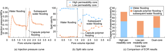
Fig. 14. Dynamic analysis of dual-core flooding experiment with capsule polymer (split ratio is the ratio of flow rate in one core to the total flow rate in the dual-core experiment). |
3. Numerical simulation of the reservoir by capsule polymer flooding
3.1. Characterization of controllable viscosity increasing mechanism of capsule polymer
Unlike traditional polymer flooding numerical simulation, which primarily uses a viscosity-concentration relationship to characterize viscosity enhancement mechanisms, the triggered release of capsule polymers is influenced by reservoir temperature, salinity and aging time. Therefore, it is necessary to establish a new model to represent the viscosity enhancement process. In this study, we developed an empirical model based on chemical reaction kinetics to characterize the process of polymer release from the capsule. The relevant parameters in this model can be determined by fitting the performance evaluation data of the capsule polymer and oil displacement experimental results through numerical simulations.
The chemical reaction kinetics model of viscosification by release of capsule polymer is as follows:
Ccp→Cp
Arrhenius formula was used to characterize the reaction rate of the viscosity-increasing process [16]:
The expression of the reaction rate constant rc was obtained through experimental fitting:
where
In the process of viscosity increasing of the capsule polymer, the solution viscosity was calculated according to the linear mixing formula based on the viscosity of both unthickened case and fully thickened case:
3.2. Numerical simulation of capsule polymer flooding
Taking the parameters of Neogene Guantao Formation 1+2 sublayers (Ng1+2) capsule polymer flooding test area in Zhong 1 Area of Shengli Gudao Oilfield as an example, the conceptual model of five-point well pattern composed of one injector and four producers was established to carry out the deep-targeted viscosity increase and production dynamic analysis of capsule polymer flooding. The model covers an oil reservoir area of 0.076 km2 with an average effective thickness of 12 m and petroleum initially-in-place of 19.73×10⁴ t. The average porosity of the model is 30%, with an average permeability of 2 000× 10−3 μm2, exhibiting heterogeneous distribution and a permeability variation coefficient of 0.5. The original formation pressure of the reservoir is 10.0 MPa, the reservoir temperature is 64 °C, the reservoir water salinity is 20 000 mg/L, the original oil saturation is 64%, and the in-situ crude oil viscosity is 80 mPa·s. The geological model grid is divided into 23×23×5 cells with grid spacings of 12.0, 2.0 and 2.4 m, respectively. The permeability distribution and well locations are shown in Fig. 15 . By fitting the physical properties of the capsule polymer obtained in the experiment, the relevant mechanistic characterization parameters are determined as follows: Tmin=60 °C, Tmax=90 °C, Csmin=10 000 mg/L, a=8.8, b=6.8, and m=1.2.
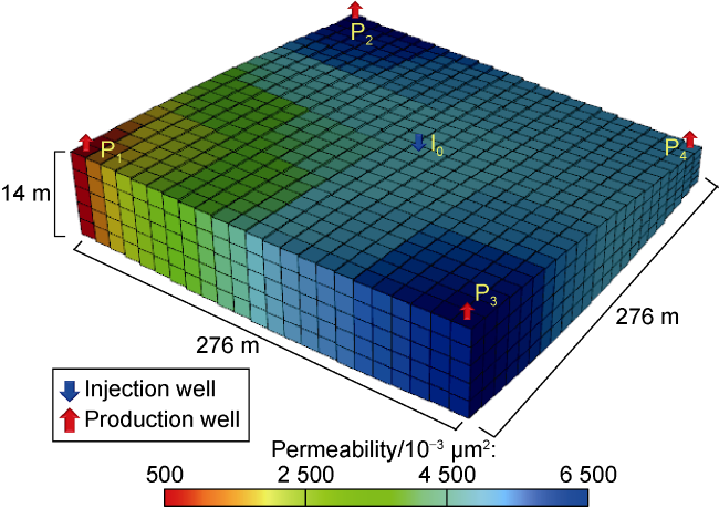
Fig. 15. Permeability and well-location distribution in the conceptual model. |
After achieving a water cut of 95% through water flooding, capsule polymer was injected using two plugs at different concentrations. The first segment consisted of 0.05 PV of the capsule polymer solution at a mass concentration of 2 200 mg/L, while the second segment involved 0.35 PV at a mass concentration of 1 665 mg/L. Following the completion of the capsule polymer injection, water flooding continued until a water cut of 98% was reached. The performance of the capsule polymer flooding was compared with both water flooding and traditional polymer flooding under the same injection conditions (Fig. 16 ). From the water cut curves, it is evident that the capsule polymer flooding exhibited a deeper and broader drawdown cone compared with traditional polymer flooding, indicating better water control during the displacement process. The ultimate recovery factor for water flooding was 39.68%, while traditional polymer flooding achieved an ultimate recovery factor of 46.89%, and capsule polymer flooding reached 50.14%. Compared with water flooding, traditional polymer flooding improved the recovery factor by 7.21 percentage points, whereas capsule polymer flooding enhanced the recovery factor by 10.46 percentage points. These results demonstrate that capsule polymer flooding is more effective than traditional polymer flooding, increasing the recovery factor by 3.25 percentage points.
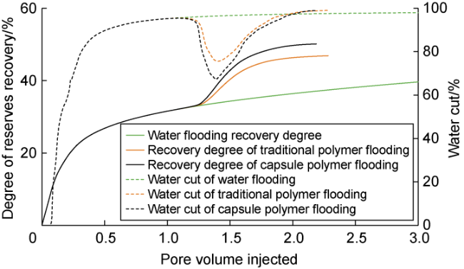
Fig. 16. Numerical simulation results of water cut and recovery degree in different schemes. |
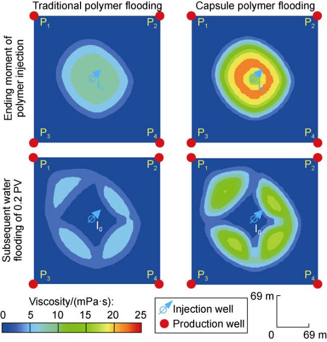
The main factor affecting the effectiveness of polymer flooding development is the viscosity of the polymer solution. A comparison of the numerical simulation results of the viscosity field between traditional polymer flooding and capsule polymer flooding at the same development stage (Fig. 17 ) reveals that: (1) During the injection phase, conventional polymers show relatively low viscosity in the near-wellbore region due to the shear of the wellbore and perforation. In contrast, capsule polymers exhibit a delayed thickening characteristic, with viscosity being lower near the wellbore but higher in the targeted area. This enables capsule polymers to advance more quickly along high-permeability zones. After thickening, the viscosity of the aqueous phase in the target area is notably higher, providing enhanced control over the injected water. (2) In the subsequent water flooding phase, conventional polymers tend to flow along the main streamline, leading to a rapid decrease in viscosity, which makes it challenging to maintain effective control over an extended period. However, capsule polymers maintain a high viscosity retention rate after thickening in the deeper reservoir. Even after 0.2 PV of subsequent water injection, they can sustain a relatively high viscosity, which is more favorable for controlling flow along the main streamline, while promoting the diversion of subsequent water flooding, thereby improving sweep efficiency.
Fig. 17. Comparison of viscosity field between traditional polymer flooding and capsule polymer flooding. |
The capsule polymer flooding enhances oil recovery by controlling the spatial and temporal distribution of the viscosity field of the displacing fluid. During the application of capsule polymer flooding in oilfields, the design of capsule polymer particle size, injection method, and injection parameters should be based on the actual reservoir conditions. For medium to low permeability reservoirs, the particle size of the capsule polymer should not be too large. For offshore reservoirs with large well spacing and high injection rates, attention should be paid to strengthening the shell layer and improving the shear resistance. In strongly heterogeneous high-permeability reservoirs, the capsule particle size should be appropriately increased to facilitate near-well profile control, provided that injectability is ensured. Furthermore, the selection of shell layer materials and the type of polymer core should be tailored according to the characteristics of the reservoir, and the polymer release timing should be designed reasonably based on the distribution of residual oil.
4. Conclusions
A novel method to enhance oil recovery using capsule polymers has been proposed, allowing the polymers to possess advantages such as easy injectability, shear resistance, controlled release in formations, and low adsorption retention. This method realizes the conceptual shift of polymer flooding from ground dissolution thickening to deep reservoir thickening.
The capsule polymer is a rigid and stable particle at room temperature. When subjected to the reservoir temperature, the capsules release the polymer in response to thermal stimulation. The higher the temperature, the faster the polymer is released. The flow characteristics of capsule polymers exhibit time-varying behavior. The viscosity of the non-thickened capsule polymer solution is comparable to that of water, resulting in low injection pressure, while the viscosity and elasticity of the thickened capsule polymer solution increase simultaneously, effectively suppressing viscous fingering and expanding the sweep efficiency.
Capsule polymer flooding achieves more sustained mobility regulation through the delayed release of polymers. During the field application of capsule polymer flooding, it is essential to optimize parameters such as particle size, shear resistance, and release time of the capsule polymers based on the reservoir geological conditions and injection-production parameters. This ensures a targeted thickening effect of the displacing fluid in the deep reservoir, subsequently improving oil recovery significantly.
Nomenclature
a, b—fitting undetermined coefficients for the experiment, dimensionless;
Ccp—mass fraction of unthickened polymer capsule, %;
Cp—mass fraction of polymer after fully thickening, %;
Cs—salinity, mg/L;
Csmin—reference minimum salinity, mg/L;
Ea—activation energy, J/mol;
fw,i—molar fraction of component i-th in the aqueous phase, dimensionless;
i—component serial number;
m—fitting undetermined coefficient for the experiment, dimensionless;
n—reaction order, dimensionless;
nwc—number of components in the aqueous phase;
rc—reaction rate constant, d−1;
R—universal gas constant, J/(mol·K);
rp—reaction rate, d−1;
So—oil saturation, %;
T—temperature, K;
Tmax—maximum reference temperature, K;
Tmin—minimum reference temperature, K;
t1/2—the half-life of viscosity enhancement of the capsule polymer, d;
X, Y—horizontal and vertical coordinates, mm;
μw—viscosity of the aqueous phase, mPa·s;
μw,i—viscosity of the i-th component in the aqueous phase, mPa·s.