

Introduction
Conventional exploitation techniques are unable to meet the development requirements of shale gas reservoirs, which are characterized by ultra-low permeability, strong heterogeneity and natural fractures. By introducing horizontal well fracturing technology abroad, the shale gas in China is universally developed under the factory-like operation mode, which has significantly increased the shale gas production in China [1⇓-3]. However, this mode is sensitive to the features of small well spacing, small cluster spacing, large displacement and natural fracture (NF) development, and the zipper fracturing suffers from difficult prediction of fracture propagation trajectory, serious interference between hydraulic fractures, and frequent inter-well frac-hits [4-5]. The unclear patterns of fracture propagation and intersection under the factory-like operation mode are urgently to be addressed in the three-dimensional development of shale gas.
Previous studies have been focused on the hydraulic fracture propagation. Most scholars investigated the physical process of synchronous or zipper propagation of fractures in multiple clusters by considering the reservoirs as homogeneous objects while ignoring the presence of natural fractures. A few scholars incorporated the influence of weak plane structure on reservoirs, but did not deal with the behaviors of fracture propagation and intersection during zipper fracturing. Roussel and others conducted simulations on fracture propagation with respect to various factors such as fracture initiation sequence, cluster spacing, stress difference, and displacement by employing the displacement discontinuity method and disregarding the influence of natural fractures. They found that alternating fracturing operation leads to more uniform fracture propagation, while synchronous fracturing operation creates fractures that propagate preferentially on both sides and are suppressed in the middle, with a more uniform pattern under the conditions of larger cluster spacing, higher stress difference and lower displacement [6⇓⇓-9]. Zou et al. studied the propagation of single-cluster and multi-cluster natural fractures and the mechanism of interaction between hydraulic fractures and natural fractures from the perspectives of cementation strength, approaching angle, stress difference and displacement [10⇓⇓⇓⇓-15], but they did not involve the propagation of fractures during zipper fracturing in double horizontal wells. Hou et al. established a fracture propagation model considering the influence of natural fractures to analyze the process of fracture propagation in case of competitive fracture initiation. They revealed that natural fractures significantly impact the trajectory of fracture propagation and the formation of complex fracture network, but did not probe into the fracture propagation process of zipper fracturing [16⇓⇓⇓-20]. Wu et al. investigated the propagation of single-cluster and multi-cluster fractures between wells in homogeneous reservoirs, and discussed the fracture propagation patterns of zipper fracturing from the aspects such as fracturing sequence, well spacing and cluster spacing [21⇓⇓⇓-25]. The above studies considered the impacts of zipper fracturing, but did not cover the influence of natural fractures or fracture zones on the fracture propagation and intersection of zipper fracturing due to the limitation of numerical simulation technology.
Generally, it is evident that the propagation of single- cluster and multi-cluster fractures in well(s) has been studied, without considering natural fractures. Nonetheless, the fracture propagation and intersection patterns of zipper fracturing in the presence of natural fracture zone remain to be further investigated. In this paper, a fluid- solid coupling numerical model for zipper fracturing was built using the finite-discrete element method (FDEM). With this model, and depending on the parameters of geological features from the W platform in southern Sichuan Basin, the influence of natural fracture zone on the inter-well fracture propagation and the mechanism of fracture intersection in the presence of natural fracture zone were discussed. The resultant findings are expected to be referential for the implementation of zipper fracturing under the factory-like operation mode.
1. Model construction
1.1. Conceptual model
The factory-like operation mode has been widely applied in development of shale gas reservoirs with presence of natural fractures. To investigate the impacts of natural fracture zones on the fracture propagation and intersection of zipper fracturing, a conceptual model of zipper fracturing was established as shown in Fig. 1 , where the natural fracture zone is characterized by discrete clusters of natural fractures. With this model, the three stages (fracturing of horizontal well a, pump shutdown, and fracturing of horizontal well b) of field zipper fracturing were stimulated. Through the sequential coupling simulation, the interference between the fracturing well and the response well was captured.
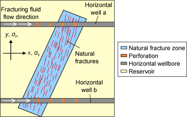
Fig. 1. Conceptual model of zipper fracturing for double horizontal wells. |
1.2. Mathematical model
The model proposed herein is based on fluid-solid coupling, and addresses inherent drawbacks in conventional models, such as small scale and costly computation. It utilizes a sequential coupling method to naturally integrate parameters such as stress, fracture trajectory, and pore pressure in the processes of response well fracturing, shut-in, and stimulated well fracturing. Following the chronological order of field operations, the model achieves continuous simulation on a large scale and across multiple processes, without the necessity of data processing or external calls.
FDEM is realized basically by discretizing the continuum in simulation domain into a finite number of triangular element meshes and inserting joint elements along the common edges of all adjacent elements (Fig. 2a ). Due to the cohesive effect of the joint elements, the initiation and propagation of matrix and natural fractures can be characterized by the damage and failure of the joint elements. When the joint elements are undamaged, the deformation of the matrix is simulated using joint elements with strong cohesion, and natural fractures are characterized by joint elements with initial thickness and cohesion (Fig. 2a ). When damaged, the joint elements form hydraulic fractures.
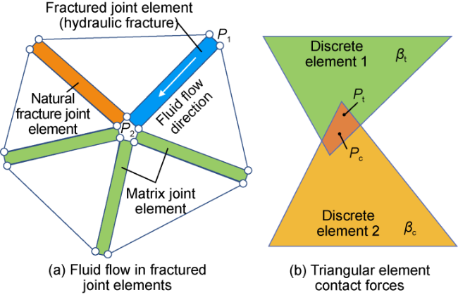
Fig. 2. Schematic diagrams of joint elements and discrete element contact. |
1.2.1. Stress balance equation
The stress distribution of any continuum can be calculated from displacement, which can be attributed to node displacement. According to FDEM, the masses, loads, displacements, velocities, and acceleration fields of triangular elements are represented by nodal values. Based on the nodal mass, contact forces, reaction forces caused by the deformation of triangular elements, and the cohesive stresses at the nodes, combined with Newton's second law, the positions and velocities of these nodes can be determined by the governing equation as follows [26]:
1.2.2. Contact force calculation equation
To calculate the contact force, the first step is to find the contact pair. In FDEM, the No Binary Search (NBS) algorithm proposed by Munjiza is used to determine the contact relationship between element nodes [27]. The contact detection time of this algorithm is linearly related to the number of elements, resulting in high efficiency for contact determination. The contact force at nodes consists of two components: the normal contact force and the tangential contact force. The normal contact force is calculated using the penalty function method, and the tangential contact force using the Coulomb friction law. The normal contact force between two triangular elements is (Fig. 2b ) [28].
Mahabadi et al. proposed a method for calculating tangential contact force in two-dimensional FDEM based on the Mohr-Coulomb friction criterion [29].
1.2.3. Stress calculation of the triangular element
The total strain of triangular elements can be computed using the current and initial displacements of the elements. Subsequently, based on the stress-strain constitutive relationship, the stress of the isotropic linear elastic triangular element with viscous damping can be determined [28].
1.2.4. Fluid flow model
Based on the Kirchhoff's Law, bottomhole pressure can be represented by the wellbore friction, perforation friction, and the pressure at the fracture inlet.
The inflow from each cluster of fractures satisfies the law of conservation of mass.
For the fluid flow inside the fracture, as shown in Fig. 2a , p1 and p2 are the pressures at nodes P1 and P2, respectively. The total pressure difference between P2 and P1 is calculated as follows [30]:
According to the Cubic law, the flow rate between P2 and P1 is calculated as follows:
The fluid exchange between two sides of fractured joint elements and the rock matrix per unit time is calculated as follows:
The fluid inside the fractured joint element enters the matrix pores under high pressure, and in FDEM, the seepage occurs between unfractured joints of adjacent triangular elements. According to the Darcy's Law, the flow velocity per unit cross-sectional area can be expressed as:
For any given element, the change in fluid pressure can be calculated by:
1.2.5. Fracture model of joint element
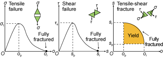
The proposed model defines three fracture modes for joint elements: Type I (tensile failure), Type II (shear failure), and Type I-II (tensile-shear failure). The damage factor d (which ranges from 0 to 1) is defined to quantitatively characterize the failure degree of joint element. When d=0, it indicates no damage; when d=1, it signifies complete damage, meaning that the joint element is fractured.
1.2.6. Fluid-solid coupling framework
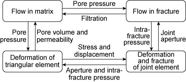
Fig. 4. Fluid-solid coupling framework based on FDEM. |
2. Model verification
2.1. Intersection of hydraulic fractures with natural fractures
The accuracy of characterizing the propagation behavior after hydraulic fractures intersecting with natural fractures is crucial for accurately simulating the hydraulic fracturing process in fractured formation. Blanton's criteria for the intersection of hydraulic fractures with natural fractures, which were obtained through physical experiments and have been widely recognized [31], are adopted to validate the model proposed in this paper. A model of the intersection between hydraulic fractures and natural fractures, with dimensions of 10 m×20 m×10 m, was established based on FDEM. Under the conditions of a horizontal principal stress difference of 2 MPa, an injection rate of 1 m³/min, and a viscosity of 3 mPa·s, the propagation pattern of hydraulic fracture intersecting with natural fracture at various approaching angles was simulated, as illustrated in Fig. 5 . It can be observed that at the approaching angles of 30° and 45°, the hydraulic fracture is captured by the natural fracture, while at 60°, the hydraulic fracture crosses through the natural fracture. The results from 12 rounds of simulations, as shown in Fig. 6 , demonstrate that under varying conditions of horizontal principal stress difference and approaching angle, the propagation pattern of hydraulic fracture intersecting with natural fracture aligns precisely with the region delineated by the boundary of the Blanton propagation model. This confirms the accuracy and reliability of the model proposed in this paper.
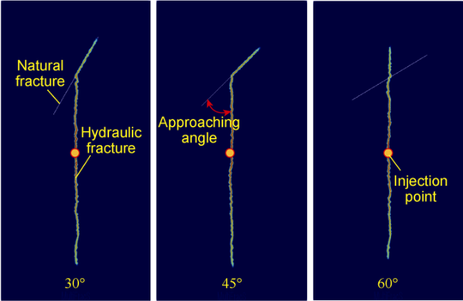
Fig. 5. Hydraulic fracture propagation pattern at different approaching angles. |
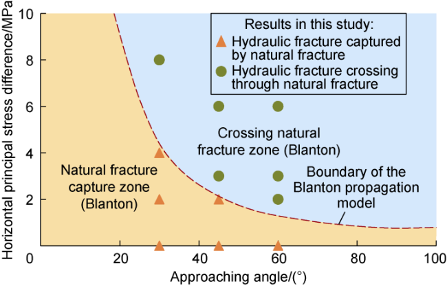
Fig. 6. Comparison of simulation results in this study with Blanton experimental results. |
2.2. Field example
In the deep shale gas reservoirs of the W platform in southern Sichuan Basin, natural fractures are highly developed but not regular in distribution. During the hydraulic fracturing of six horizontal wells on this platform, the natural fracture zones led to noticeable pressure increases in adjacent wells and severe inter-well frac-hit. To further verify the model proposed in this paper, a zipper fracturing model was established based on the geological parameters of Stage 13 of Well 2 (response well) and Stage 12 of Well 3 (stimulated well) on this platform, combined with the distribution of fracture zones displayed by ant bodies, as shown in Fig. 7a . Based on the logging curves and experimental data, the target interval is known to have the maximum horizontal principal stress of 95 MPa, the minimum horizontal principal stress of 85 MPa, the elastic modulus of 34 GPa, and the Poisson's ratio of 0.2. The fracturing stage is designed with 5 clusters of fractures, a displacement of 14 m³/min, and a well spacing of 300 m. Considering the possibility of inter-well frac-hit by fracture zones, the total injected fluid volume is reduced to 1 600 m³. Based on the field operation parameters and the proposed model, the fracture distribution and surface pressure curves for the target interval at three fracturing stages were simulated, as illustrated in Fig. 7b -7d and Fig. 8 . From the fracture distribution, it can be observed that under the influence of natural fracture zones, the hydraulic fractures of the two wells are eventually intersected. Upon comparison, it is clear that the simulated pressure curves basically match the monitored pressure curves for the stimulated well and the response well. The simulated and monitored pressures increase by 6.5 MPa and 6.0 MPa, respectively, suggesting an accuracy rate of 91.6%, which indicates that the model proposed in this paper is highly accurate.
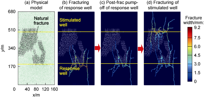
Fig. 7. Physical model of example wells and distribution of fracture propagation trajectory. |
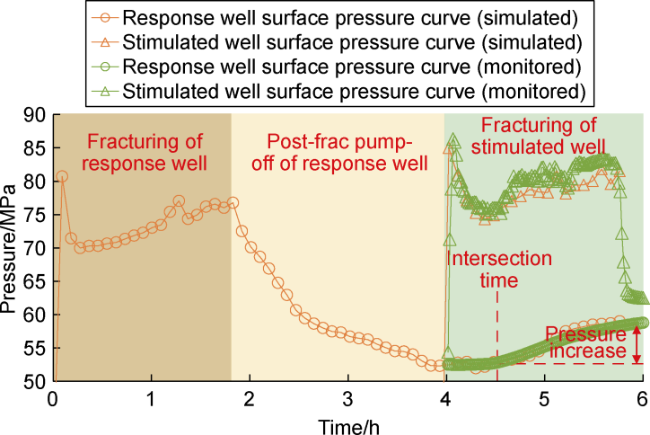
Fig. 8. Comparison of simulated and field monitored surface pressure curves. |
3. Influential factors for fracture propagation and intersection
3.1. Model building and input parameters
Based on the physical parameters of Stage 20 of Well 5 (response well) and Stage 21 of Well 6 (stimulated well) on the W platform, a dual-horizontal well zipper-fracturing physical model was established, as depicted in Fig. 9 . The model has the dimension of 100 m×200 m×10 m, and is divided into 42 680 discrete elements, with 3 perforation clusters per stage. The natural fracture zone consists of densely distributed natural fractures, and the approaching angle of the natural fractures is consistent with that of the fracture zone. The fracture zone is located between two horizontal wells. To accurately observe the inter-well frac-hit, three consecutive stages were simulated: fracturing of response well, post-frac pump-off of response well, and fracturing of stimulated well. All operation parameters of the two wells are consistent, and the basic parameters are shown in Table 1. The main focus of the research is on the influences of the approaching angle of the fracture zone, the length of natural fractures within the zone, the fracture zone width, and the relative position between the fracture zone and the perforations on the fracture propagation and intersection of zipper fracturing.
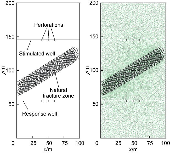
Fig. 9. Physical model of dual-horizontal-well zipper- fracturing and discretize mesh grid. |
Table 1. Main basic parameters of the W platform |
| Parameter | Value | Parameter | Value |
|---|---|---|---|
| Porosity | 4.8% | Matrix internal friction angle | 30° |
| Vertical principal stress | 96 MPa | Matrix tensile strength | 15 MPa |
| Minimum horizontal principal stress | 90 MPa | NF approaching angle | 5°-75° |
| Principal stress difference | 12 MPa | NF cohesion | 5 MPa |
| Formation pressure coefficient | 2.0 | NF tensile strength | 3 MPa |
| Elastic modulus | 40 GPa | NF internal friction angle | 12° |
| Poisson's ratio | 0.23 | Number of initiation clusters | 3 |
| Fracturing fluid viscosity | 3 mPa·s | Cluster spacing | 10 m |
| Fracturing fluid displacement | 8 m3/min | Fracturing time for wells 5 and 6 | 1 h |
| Matrix cohesion | 20 MPa | Pumping-off time | 1 h |
3.2. Approaching angle of fracture zone
Based on the physical model in Fig. 9 , given the natural fracture length of 20 m and the zone width of 20 m, the influences of the approaching angle of fracture zone (θ) on the fracture propagation trajectory (Fig. 10 ), fracture intersection (Fig. 11 ), and total length of hydraulic fractures (Fig. 12 ) in the zipper fracturing process were simulated. (1) In Fig. 10a , due to the capture of hydraulic fractures by natural fractures, the larger the approaching angle of the natural fracture zone, the larger the distance between the hydraulic fracture front of response well and the wellbore of stimulated well. This indicates that a fracture zone with a large approaching angle impedes the propagation of hydraulic fractures. (2) Comparing Fig. 10a and Fig. 10b , it is evident that due to the ultra-low permeability and low fluid loss of the shale matrix, hydraulic fractures continue to expand under the driving of high net pressure inside the fractures in the pump-off period. (3) Combining Fig. 10c , Fig. 11 and Fig. 12 , it is known that after the fracturing of stimulated well, when the approaching angle of the fracture zone is 15°, the hydraulic fractures in the stimulated well rapidly intersect with those in the response well through the natural fracture zone, causing a pressure increase of 8.3 MPa at 0.52 h of fracturing, due to the susceptibility of natural fractures to tensile-shear failure. When the approaching angle of the fracture zone is 60°, the hydraulic fractures of the stimulated well are initially impeded by the natural fracture zone and propagate along it. However, due to the influence of high horizontal stress difference and an increase in net pressure, when the fracturing of stimulated well reaches 0.94 h, the hydraulic fractures break through the barrier of the fracture zone and intersect with hydraulic fractures in the response well, resulting in a frac-hit, and a pressure increase of 5.4 MPa in the response well. (4) When the approaching angles of the fracture zone are 35° and 45°, hydraulic fractures preferentially propagate along the natural fractures due to obstruction by the latter, without inter-well frac-hit occurring. Clearly, with increasing approach angles, the pressure increase in the response well shows a trend of decreasing first and then increasing.
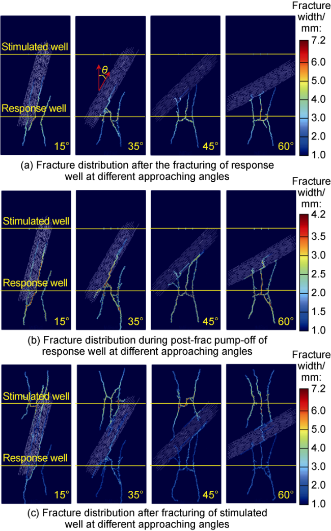
Fig. 10. Impact of fracture zone approaching angle on fracture propagation. |
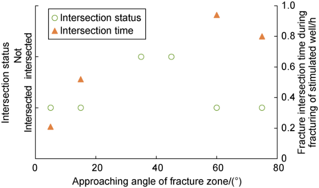
Fig. 11. Impact of approach angle on fracture intersection and intersection time during hydraulic fracturing. |
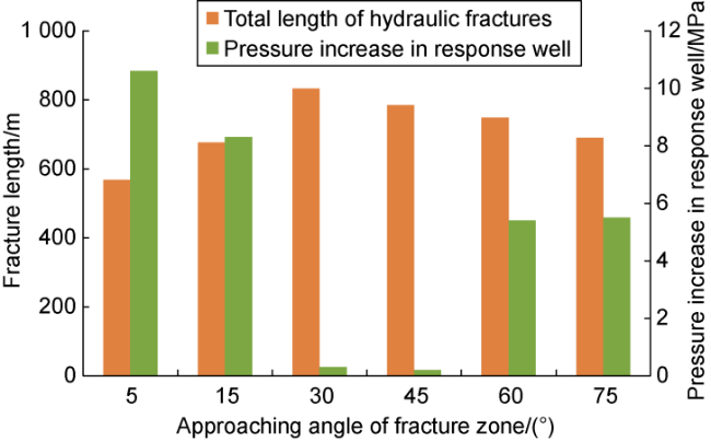
Fig. 12. Impact of approaching angle on response well pressure increase and total length of hydraulic fractures. |
To evaluate the impact of the inter-well frac-hit on the fracturing effect, the relationship between the total length of hydraulic fractures and the approaching angle of fracture zone was statistically analyzed (Fig. 12 ). Comparison of Figs. 10c , 11 , and 12 provides four findings. First, as the approaching angle of the fracture zone increases, the total length of hydraulic fractures shows a trend of increasing and then decreasing. Second, compared to fracture zones with small approaching angles, those with large approaching angles require more time for inter-well intersection, and the pressure increase in the response well after intersection is smaller, indicating greater difficulty in intersection. Third, due to the influence of inter-well frac-hit, the fracturing efficiency decreases, resulting in a reduction in the total length of hydraulic fractures in the intersecting wells. Fourth, under high stress difference, fracture zones with the approaching angles of 5° to 15° are more prone to intersect than those with the approaching angles of 60° to 75°, which are more prone to intersect than those with the approaching angles of 35° to 45°.
3.3. Fracture zone width
The width of natural fracture zone in shale reservoirs is an important factor affecting hydraulic fracture intersection. Based on the physical model in Fig. 9 , given the approaching angle of fracture zone of 30° and the natural fracture length of 20 m, the influences of the fracture zone width (wn) on the fracture propagation and intersection of zipper fracturing were simulated. Figs. 13 to 15 , respectively, depict the effects of fracture zone width on the fracture trajectory, hydraulic fracture intersection, pressure increase, and total length of hydraulic fractures at the time of pump-off during the fracturing of stimulated well. According to the analysis, when the fracture zone width is 5 m and 15 m, indicative of narrow fracture zones, there is a small resistance to hydraulic fracture propagation in the direction of the maximum principal stress. This facilitates inter-well fracture intersection, resulting in pressure increases of 7.5 MPa and 4.2 MPa in response well, respectively. When the fracture zone width is 25 m and 35 m, the wide fracture zones exhibit significant blocking effects. As a result, fracture intersection does not occur, resulting in an insignificant pressure increase in the response well. As the fracture zone width increases, the probability of inter-well fracture intersection in zipper fracturing decreases, and the time required for inter-well fracture intersection gradually increases. With increasing fracture zone width, the pressure increase in the response well decreases, resulting in more complex fractures and a greater total length of hydraulic fractures, thereby stimulating the reservoirs more efficiently.
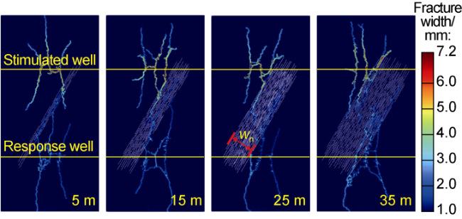
Fig. 13. Fracture trajectory at the time of pump-off during fracturing of stimulated well under different fracture zone widths. |
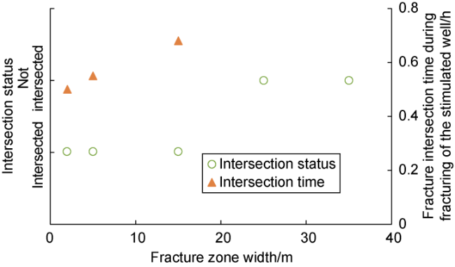
Fig. 14. Impact of fracture zone width on hydraulic fracture intersection status and time. |
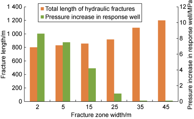
Fig. 15. Impact of fracture zone width on response well pressure increase and total length of hydraulic fractures. |
3.4. Length of natural fractures in the fracture zone
Based on the physical model in Fig. 9 , given the approaching angle of the fracture zone of 15° and the fracture zone width of 20 m, the influences of the length of natural fractures in the fracture zone on fracture propagation and intersection patterns of zipper fracturing were simulated. Fig. 16 depicts the hydraulic fracture trajectories after fracturing of stimulated well and response well. Figs. 17 and 18 respectively illustrate the intersection status in zipper fracturing under varying lengths of natural fractures, as well as the corresponding intersection time and frac-hit degree. Analysis shows that due to the smaller approaching angle of the fracture zone, inter-well fracture intersection occurs under different lengths of natural fractures. The time required for intersection decreases with increasing length of natural fractures. The pressure increase in the response well grows as the length of natural fractures increases, while the total fracture length at the end of zipper fracturing decreases with increasing natural fracture length. Accordingly, since the natural fractures with small approaching angle are easily activated and highly capable of capturing hydraulic fracture, as the length of natural fractures in the fracture zone increases, the risk of fracture intersection during zipper fracturing increases, thereby reducing reservoir stimulation efficiency. For fracture zones with wider and more continuous natural fractures, it is especially necessary to appropriately control the fluid volume and displacement and increase the fluid viscosity to prevent or delay fracture intersection where possible.
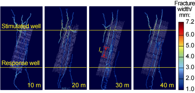
Fig. 16. Fracture trajectory at the time of pump-off during fracturing of stimulated well under different lengths of natural fractures. |
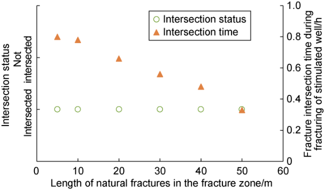
Fig. 17. Impact of natural fracture length on hydraulic fracture intersection status and time. |
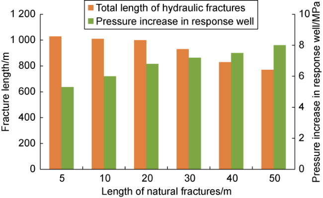
Fig. 18. Impact of natural fracture length on response well pressure increase and total length of hydraulic fractures. |
3.5. Relative position between the fracture zone and the perforation
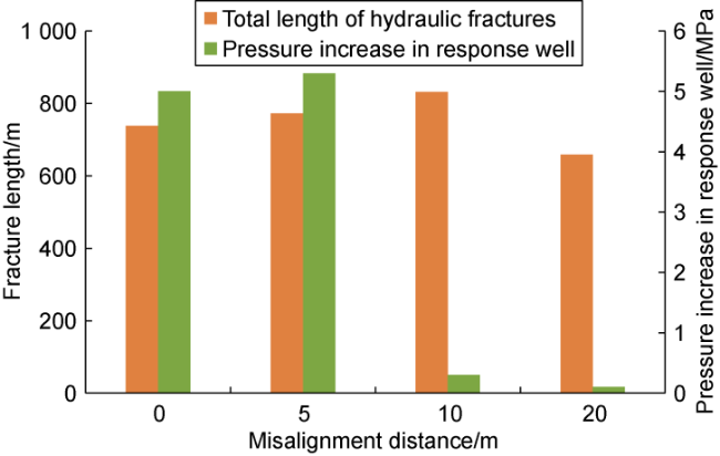
For shale reservoirs with natural fractures, horizontal well crossing fracture zone is inevitable. Optimizing the relative position between fracture zones and perforations becomes crucial for avoiding inter-well fracture intersection. Based on the physical model shown in Fig. 9 , given the approaching angle of the fracture zone of 15°, the fracture zone width of 20 m, the natural fracture length of 10 m, and the misalignment distance (ds) defined to characterize the relative position between the fracture zone and the perforation (Fig. 19 ), the influences of the relative position between fracture zone and perforation on fracture propagation and intersection patterns in zipper fracturing were simulated. Fig. 19 depicts the fracture trajectories at ds of 0, 5, 10 and 20 m. It is evident that at ds of 0 and 5 m, influenced by natural fracture zone, inter-well fracture intersection occurs during zipper fracturing. At ds of 10 m and 20 m, no fracture intersection occurs after the fracturing of two wells. This indicates that misaligned perforation has a significant impact on fracture propagation and intersection, and an increase in misalignment distance leads to a decrease in the probability of inter-well fracture intersection. According to the analysis of Fig. 20 , misaligned fracturing (ds=5 m) requires more time for inter-well fracture intersection compared to perfectly aligned fracturing (ds=0 m). Fig. 21 shows that there is no significant regular relationship between the misalignment distance and the total length of hydraulic fractures and response well pressure increase. Although fracture intersection occurs at ds of 0 m and 5 m, the pressure increase is not maximum and the total fracture length is not minimum at ds=0 m. Conversely, the pressure response is greater at ds=5 m, and the total fracture length is minimum at ds=20 m. Essentially, when the misalignment distance is 0 m and 5 m, a large proportion of hydraulic fractures fall in the fracture zone, showing relatively complex distribution. However, when the misalignment distance is 20 m, all hydraulic fractures are created in matrix, presenting relatively simple distribution.
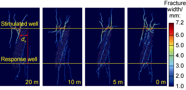
Fig. 19. Fracture trajectories at the time of pump-off during fracturing of stimulated wells under different misalignment distances. |
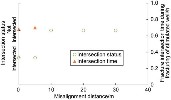
Fig. 20. Impact of misalignment distance on hydraulic fracture intersection status and time. |
Fig. 21. Impact of misalignment distance on response well pressure increase and total hydraulic fracture length. |
4. Conclusions
The fracture propagation and intersection patterns of zipper fracturing in deep shale gas reservoirs are controlled by factors such as the approaching angle of natural fracture zone, the length of natural fractures, the width of fracture zone, and perforation position. The natural fracture zone with large approaching angle impedes the forward propagation and inter-well connection of hydraulic fractures. During shutdown periods, hydraulic fractures continue to propagate under the driving of net pressure. Under high stress difference, as the approaching angle of fracture zone increases, the pressure increase of the response well tends to decrease and then increase, and the total length of hydraulic fractures exhibits the trend of increasing and then decreasing. Compared to fracture zone with small approaching angle, fracture zone with large approaching angle requires more time and presents greater difficulty for fracture intersection. The width of fracture zone and the length of natural fractures have negative and positive correlations, respectively, with the pressure increase of the response well, and exhibit positive and negative correlations, respectively, with the time required for fracture intersection, total length of hydraulic fractures, and fracturing efficiency. As the misalignment distance increases, the probability of inter-well fracture intersection decreases. However, the misalignment distance has inconspicuous correlation with the pressure increase of the response well and the total length of hydraulic fractures.
Nomenclature
a—average aperture of fractured joint element, m;
A—area of overlap between triangular elements, m2;
C—damping matrix, N•s/m;
d—damage factor, dimensionless;
ds—misalignment distance of perforation cluster between two wells, m;
det—calculate the determinant of a square matrix, dimensionless;
D—strain rate tensor, s−1;
E—elastic modulus, Pa;
Ed—Green strain tensor, dimensionless;
Es—St. Venant strain tensor, dimensionless;
fn—normal contact force, Pa;
fp—perforation friction, Pa;
fs—saturation correction coefficient, %;
ft—tangential contact force, Pa;
fw—friction along the wellbore, Pa;
F—deformation gradient matrix, dimensionless;
Fc—contact force vector at the node, N;
Fd—nodal force vector induced by the deformation of triangular elements, N;
Fj—cohesive force at the node, N;
Fext—external force vector at the node, N;
g—acceleration of gravity, m/s2;
hc—coefficient of fluid exchange between the fracture and the rock matrix, m/(Pa•s);
i—perforation cluster serial number;
K—permeability tensor, m2;
l—distance between two pressure nodes, m;
ln—length of natural fractures, m;
L—fracture length, m;
m—mass matrix, N•s2/m;
M—Biot modulus, Pa;
n, n+1—the previous time step and the current time step, dimensionless;
nhf—total number of fracture clusters;
o—normal opening amount, m;
op—critical normal opening amount, m;
or—maximum normal opening amount, m;
p—fluid pressure, Pa;
p1—node pressure at the initial end of the fracture, Pa;
p2—node pressure at the end of the fracture, Pa;
pc—fluid pressure within the fracture, Pa;
pf,in—entry pressure for each perforation cluster, Pa;
pn—normal penalty parameter, Pa/m;
, —matrix pore pressure on both sides of the fracture, Pa;
pt—tangential penalty parameter, Pa/m;
pw—bottom hole pressure, Pa;
q21—flow rate from node 2 to node 1, m2/s;
, —rate of fluid exchange between the rock matrix and two sides of the joint element, m2/s;
Qi—rate of inflow into the ith fracture cluster, m3/s;
Q—total injected flow, m3/s;
Qtotal—net flow into the element per unit time, m3/s;
s—tangential slip amount, m;
sp—critical shear slip amount, m;
sr—maximum shear slip amount, m;
t—time, s;
T—stress tensor, Pa;
V—volume of any given element, m3;
v—flow velocity of fluid passing through a unit cross-section, m/s;
wn—fracture zone width, m;
x, y—Cartesian coordinate system, m;
x—vector of nodal coordinates, m;
—nodal velocity vector, m/s;
—nodal acceleration vector, m/s2;
y1, y2—y-axis coordinates of nodes 1 and 2, m;
α—Biot coefficient, dimensionless;
βt, βc—target triangular element, contactor triangular element;
θ—approaching angle, (°);
ν—Poisson's ratio, dimensionless;
λ—viscous damping coefficient, Pa•s;
ρw—fluid density, kg/m3;
μ—fluid viscosity, Pa•s;
σ—tensile strength, Pa;
σH, σh—maximum and minimum horizontal principal stress, Pa;
σt—normal stress, Pa;
τ—shear strength, Pa;
τs—tangential stress, Pa;
Δp—total pressure difference between node 1 and node 2, Pa;
Δut—relative displacement of the contact point at a given moment, m;
, —potential at points Pt and Pc within the overlapping area, dimensionless;
—boundary of the overlapping area between target triangular element βt and contactor triangular element βc, dimensionless.