

Introduction
The continental low-permeability oilfields in China have been successively developed for more than half a century using the technology of vertical well injection and production + infill drilling. However, new challenges have emerged in the development [1-2], such as overbalanced injection-production and ineffective circulation of injected water in the Changqing Oilfield. Many researchers have worked a lot on these issues. Li et al. [3] and Li et al. [4] found through numerical simulation that there is a large amount of remaining oil on both sides and distal ends of hydraulic fractures on the plane developed by vertical well in low-permeability reservoirs. LISJAK et al. [5] and Xu et al. [6] found that the water flooding efficiency remains low vertically by observation of cores taken from inspection wells, the thickness of the layers with obvious water washing characteristics is less than 1 m, and the injected water only affects local layers. Since the remaining oil enriched area is unproduced, the formation is still in a high stress state. Controlled by in-situ stress field, the hydraulic fractures induced by conventional re-fracturing cannot directly communicate with the remaining oil enriched area. Continuous development by vertical well infilling has poor efficiency and economics. In contrast, the flexible sidetracking horizontal well stimulation technology can directly communicate with the remaining oil enriched area and achieve efficient fracturing treatment, meeting the low-cost strategy and high-quality goals [7-8].
The flexible sidetracking horizontal well stimulation technology can efficiently facilitate the recovery of remaining reserves among wells through a process where the flexible sidetracking tool is used to sidetrack old wells at a low cost, then hydraulic jetting is implemented to initiate fractures, and finally the tubing string is run for fracturing the sidetracked hole. To secure this process, two key technologies are developed: flexible sidetracking horizontal well drilling technology, and sidetracking horizontal well fracturing technology. The former enhances the technical capability of sidetracked hole to communicate with the remaining oil in the deep reservoir, while the latter improves the degree of control of fractures over the remaining oil.
1. Flexible sidetracking stimulation technology of horizontal wells
To achieve effective communication between the remaining oil enriched area and the main wellbore, the flexible drill pipe sidetracking technology is used to drill ultrashort-radius horizontal well. Specifically, the flexible drill pipe consisting of several subs (0.10-0.25 m long for each) that are hinged in sequence is connected with a drill bit to transmit the weight on bit (WOB) and torque from the surface to the cutting face of the bit, which will drill into the remaining oil enriched area by way of mechanical rock breaking. The curvature radius of the build section is 2-4 m, the diameter of the sidetracked hole in 139.7 mm cased wellbore exceeds 118 mm, and the maximum horizontal footage can reach 100 m theoretically. So far, this technology has improved significantly, and it is especially advantageous in aspects such as wellbore diameter, drilling cost and coring [9-10].
Many enterprises and universities, such as China National Petroleum Corporation (CNPC), China National Offshore Oil Corporation (CNOOC), and China University of Petroleum (Beijing), are conducting research and development on flexible drill pipe sidetracking technology. This technology has been applied in numerous oil and gas fields in China, with some initial results achieved. However, it is found with unobvious stimulation effect in low permeability oil reservoirs, due to short ultimate horizontal footage of sidetracking, poor directional control accuracy and ill-defined remaining oil distribution. This paper presents the optimization of flexible drill pipe structure and material and the improvement of drilling process to enhance the ultimate horizontal extension capacity and drilling direction control accuracy, and the research and development of flexible sidetracking and sealed coring technology to further probe into the reservoirs around the wellbore.
1.1. Optimization of flexible drill pipe structure and material
We designed and developed a constant angular acceleration flexible drill pipe made of 40CrNiMoA alloy structural steel. However, tests have revealed a lot of problems when the horizontal section exceeded a certain length, such as frequent occurrence of string break, and failure of WOB and torque transmission to the bit. These problems limit the length of horizontal section. Therefore, considering the requirement of flexible sidetracking horizontal well stimulation technology, the structure and material of key parts of the flexible drill pipe were optimized.
The subs of the flexible drill pipe are connected by threads (Fig. 1 ). Since the threads have lower strength than the pipe body, the drill pipe is frequently subjected to thread off and sliding at normal working loads, due to the bucket effect. First, hardness tests were conducted on the materials of three key parts of the flexible drill pipe: universal joint housing, ball head and end shield. Three specimens were randomly selected for each part, and full wall thickness strip samples were taken along the axial direction from the middle part of each specimen and then tested for Rockwell hardness (HRC) according to the standard GB/T 230.1-2018 [11]. Then the HRC was converted to Brinell hardness (HB). The test results are given in Table 1 . It is indicated that the hardness of the end shield material is low, and the nitriding process needs to be further optimized.
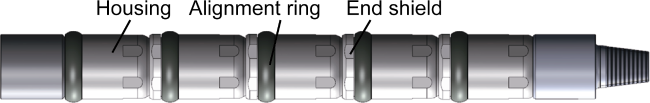
Fig. 1. 3D model of flexible drill pipe. |
Table 1. HB test results of samples. |
| Sample | Brinell hardness | ||
|---|---|---|---|
| Specimen 1 | Specimen 2 | Specimen 3 | |
| Universal joint housing | 339 | 340 | 340 |
| Ball head | 305 | 304 | 297 |
| End shield | 261 | 266 | 267 |
Second, mechanical performance tests were conducted on the material of flexible drill pipe. For this purpose, the indentation test was used instead of traditional tensile test, because the flexible drill pipe is too small to yield qualified samples. During the indentation test, an indenter was used to continuously load and unload the sample to obtain the load-indentation depth curve. Then, the elastic modulus of the material was determined based on the unloading segment data of the curve. Finally, the stress-strain curve, tensile strength and yield strength of the material were obtained depending on the relationship between the indentation load and depth. In this study, column plane indentation tests were conducted on three parts: ball head, end shield, and universal joint housing, and each part was tested at 3 points. The test results are listed in Table 2 .
Table 2. Mechanical parameters of materials |
| Tested part | Test point | Elastic modulus/GPa | Tensile strength/MPa | Yield strength/MPa |
|---|---|---|---|---|
| Universal joint housing | 3-1# | 219.7 | 1 138.3 | 976.1 |
| 3-2# | 210.2 | 1 132.6 | 972.6 | |
| 3-3# | 221.5 | 1 134.0 | 968.1 | |
| Ball head | 1-1# | 219.9 | 1 068.2 | 854.0 |
| 1-2# | 218.1 | 1 074.3 | 883.7 | |
| 1-3# | 214.7 | 1 066.8 | 859.7 | |
| End shield | 2-1# | 209.1 | 900.3 | 695.8 |
| 2-2# | 211.8 | 901.4 | 678.6 | |
| 2-3# | 213.5 | 910.7 | 701.8 |
Cracks were observed macroscopically on the surface of the end shield, so samples were taken from the crack location shown in Fig. 2a for metallographic examination. The root crack is shown in Fig. 2b . As shown in Fig.2a , there are several cracks, starting from the internal surface, on the internal thread section of the end shield, and no anomaly is observed in the texture near the cracks.

Fig. 2. Crack morphology at thread of end shield and root crack. |
Based on the analysis results of material properties and cracks, stress simulation analysis was conducted on the broken parts. Axial compressive and torsional loads were applied on the broken part model. The torque was 6, 8, 10 and 12 kN·m, respectively, and the axial pressure was 40 kN. Simulation was conducted on the stress status of the model under four working conditions using the explicit dynamic finite element method. The equivalent stress distribution of the flexible drill pipe was obtained by elasto-plastic analysis. Fig. 3 shows the equivalent stress distribution of the end shield when the torque is 12 kN·m. Obviously, the maximum equivalent stress of the flexible drill pipe is located at the escape root of the end shield thread, which is consistent with the root crack position of the thread. When the torque is 12 kN·m, the maximum equivalent stress is 909 MPa, exceeding the yield strength of 40CrNiMoA alloy structural steel (835 MPa). When the torque is 10 kN·m, the maximum equivalent stress is 757 MPa, which is less than the yield strength of 40CrNiMoA alloy structural steel. It is inferred that the thread structure of the end shield is relatively safe when the working torque of the flexible drill pipe is controlled below 10 kN·m. However, the downhole torque cannot be accurately controlled during field operations. Therefore, the thread structure needs to be optimized depending on the crack analysis and stress simulation analysis results.
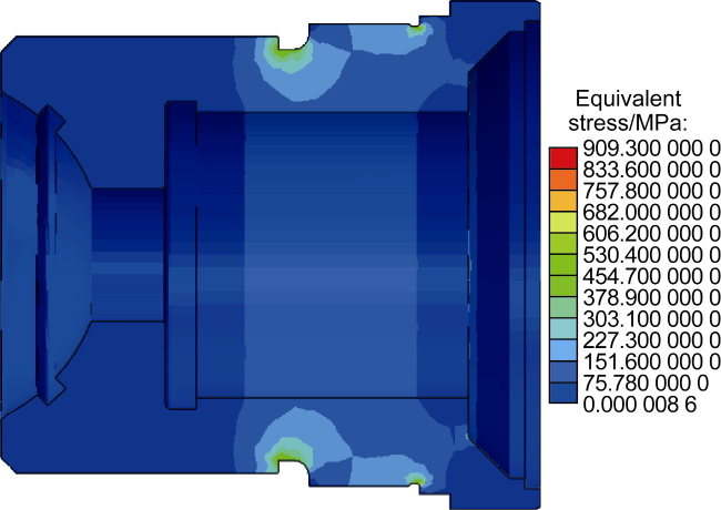
Fig. 3. Equivalent stress distribution of end shield at a torque of 12 kN·m. |
The thread pitch was increased from 6 mm to 10 mm, and the thread angle was increased to 30°, effectively increasing the root width. Furthermore, a circular arc transition was added at the root to improve the root strength and alleviate stress concentration while ensuring sealing ability. The inspection shows that the optimized thread does not have apparent damage under a torque of 20 kN·m, and its torsional capacity is significantly improved compared to the existing structure [10].
The original material 40CrNiMoA of the flexible drill pipe body is a kind of medium-carbon low-alloy high-strength steel. This material after oil quenching at 850 °C and tempering at 600 °C has the yield strength of 840-850 MPa, tensile strength of 983-997 MPa and elongation of 11%-13%. Despite of good mechanical properties, it may be susceptible to fatigue failure and severe wear when it is used as the material of flexible drill pipe body. The current material needs to be improved. By means of quenching + high temperature tempering tests, a low-carbon low-alloy high-strength malleable steel was selected. After oil quenching at 850 °C and tempering at 540 °C, this steel material exhibits the yield strength of 930-945 MPa, tensile strength of 1 090-1 170 MPa and elongation not less than 10.5%. In addition, considering the relatively low carbon content in the material, addition of Ni and Mo alloying elements allows for refinement of the martensitic structure and the sorbitic structure subsequently formed by high-temperature tempering, thus improving the impact toughness after tempering (Fig. 4 ). According to laboratory test results, the impact energy reaches 71 J. Therefore, the improved material has better mechanical properties, and can effectively enhance the strength of the drill pipe.
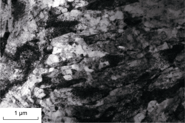
Fig. 4. Sorbitic structure and nodular cementite after quenching and high-temperature tempering of the improved material. |
To solve the problems such as high transmission drag and severe wear at the hinge joint of flexible drill pipe, according to the concept of bionics, by imitating the structure of skeletal joints, the outer surface of the ball socket in direct contact with the drill pipe ball head was replaced with a softer copper-based composite material, achieving the goal of reducing friction and drag. Friction/wear tests were conducted, showing that during the friction process, the wear scar depth, debris quantity and oxide quantity of the copper-based composite material are small, and the wear rate, friction coefficient and fluctuation are apparently lower than those of the original material. These features help effectively reduce the torque transmission loss between drill pipes, and allow the bit to obtain sufficient rock breaking energy even if the horizontal section is overlong. Finite element analysis was conducted to obtain the stress distribution at hinge assembly of the copper-based composite material (Fig. 5 ), showing that the maximum equivalent stress of the ball head on the assembly is 386.32 MPa, located at the seal groove of the ball head. The equivalent stress of the contact surface between the copper-based alloy ball socket and ball head is 150-160 MPa (the yield strength of the copper-based alloy is 350 MPa). After interference assembling, neither the ball head nor the ball socket undergoes plastic deformation, indicating that the hinge joint can still maintain the required flexibility under normal load.
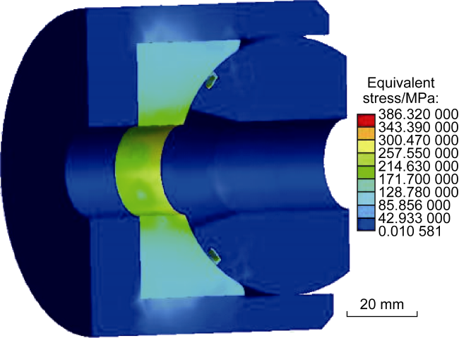
Fig. 5. Stress distribution of hinge assembly of the copper-based composite material. |
1.2. Improvement of drilling process
The effectiveness of the flexible sidetracking horizontal well technology depends on equipment and tools, and also on the optimization of drilling process. The flexible drill pipe adopts a hinged structure, which enables it to have excellent bend throughput capacity. However, the lack of rigidity makes the flexible drill pipe far inferior to conventional drill pipes in terms of force transmission efficiency, strength and structural stability, resulting in a series of problems such as low transmission efficiency, high drilling risk and poor directional control accuracy. To solve these problems, the drilling process was improved from various aspects such as dynamic analysis and laboratory experiment optimization.
First, a multi-body dynamic analysis was conducted to explore the downhole dynamic properties and load transfer patterns of flexible drill pipe, and clarify the relationships between drilling process parameters (e.g. WOB, rotation speed) or wellbore geometry parameters (e.g. wellbore curvature radius, horizontal section length, and wellbore diameter) and the motion and stress states of flexible drill pipe, laying a foundation for the design of drilling process. Second, a test bench for sidetracking scaled model of flexible drill pipe was built (Fig. 6 ) according to the similarity theory. Combined with a high-speed camera, the eddy current displacement sensor can collect the displacement at any section of the flexible drill pipe. The dynamic torque sensor, tension sensor and compression/torsion sensor can synchronously collect WOB, torque and friction. The real downhole motion and stress states of drill pipes were restored through scaling transformation, thereby assisting in improving the setting of multi-body dynamics model parameters and boundary conditions.
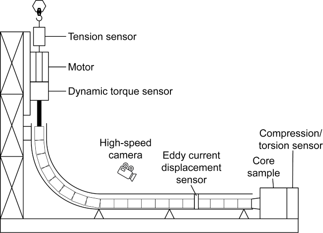
Fig. 6. Test bench for sidetracking scaled model of flexible drill pipe. |
The above research results were applied to guide the field operations of drilling process. With the help of the improved flexible drill pipe, the WOB and rotation speed were properly controlled through easing the bit in light pressure, so that the problems of low transmission efficiency and high drilling risk of flexible drill pipe were effectively solved. At present, the maximum length of horizontal section reaches 80 m, and the risk of drill pipe breakage and falling into the well is significantly reduced.
Considering the problem of "inaccurate drilling" caused by poor directional control accuracy, a causal chain analysis was conducted. It is found that the primary cause is the overlong rigid length of the downhole motor, which is not suitable for directional build-up during flexible sidetracking. Under current technical conditions, the sidetracking azimuth is orientated only relying on whipstock, and the tool face is uncontrollable during kick off and build-up processes [10]. A flexible turbodrill directional drilling technology was proposed. The conventional turbodrill is transformed for flexibility to allow it to penetrate deep into the curved portion during build-up process. With the help of gyroscopic orientation measurement, the face of the drilling tool is controlled to make the azimuth error below ±10°. Meanwhile, the application of flexible turbodrill realizes downhole drive during the process of build-up and horizontal drilling. The upper flexible drill pipe only bears the reactive torque of turbine. Since this torque is smaller than the torque of rotary table, the drill pipe breakage risk is reduced.
1.3. Flexible sidetracking and sealed coring technology
To accurately understand the distribution of remaining oil and further evaluate the oil reservoirs encountered by sidetracking horizontal well, the flexible sidetracking and sealed coring technology was developed. In contrast to early coring tools which take cores with small diameter and susceptibility to downhole fluid contamination, an ultrashort-radius large-diameter flexible sealed coring tool (Fig. 7 ) was innovated by integrating the articulated flexible drill pipe and sealed coring barrel. The articulated structure was optimized to improve the integrity of the core, and the core barrel was prefilled with sealing fluid to isolate drilling fluid contamination. According to design, the coring diameter is 42 mm, and the coring length in a single trip reaches 1.5 m.
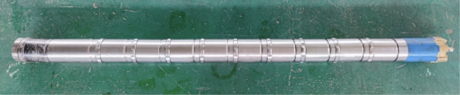
Fig. 7. Prototype of flexible sidetracking and sealed coring tool. |
The coring tool contains a sealing mechanism, which releases sealing fluid to enwrap the core when it enters the core barrel, so as to preserve the information contained in the core as much as possible. The core barrel is made of TC4 pipe with an outer diameter of 55 mm and an inner diameter of 42 mm. Sealing fluid is prefilled, and a core barrel sealing mechanism with check valve as its main structure is designed near the bit to ensure the sealing fluid not to flow out. During the coring process, the sealing mechanism is opened by the compression of the core, so that the sealing fluid flows out to wrap around the core. The mechanism gradually enters the core barrel along with the core. After core drilling is completed, the ball-dropping pressurizing method is used to push the core catcher to shrink radially and cut the core. To verify the coring effect, laboratory coring experiment was conducted using the flexible sidetracking and sealed coring tool, with results shown in Fig. 8 . In the experiment, the rotation speed was 40 r/min, the WOB was 1 t, the torque was 300 N·m, the coring footage was 1 500 mm, and the drill time was 48 min. The experimental results show that the sealing fluid can uniformly enwrap the core. After removing the sealing fluid on the surface of the core, the core diameter and length were measured to be 41.8 mm and 1 450 mm, respectively, and the core recovery reached 97%.
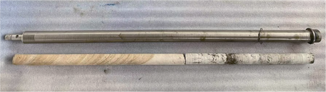
Fig. 8. Coring experiment results. |
2. Sidetracking horizontal well fracturing technology
Depending on the characteristics of flexible sidetracking horizontal wells, it is proposed to use a flexible expanding open hole packer to pack off the area near the old wellbore, then use sand jet perforation to induce fractures in the horizontal open hole, and finally conduct sand fracturing [12-13]. Jetting forms a hole at a certain depth by overcoming the formation breakdown pressure, generating a mechanical weakness in the open hole section, so as to induce the initiation and propagation of hydraulic fractures during fracturing operation [14-15]. In this way, the sidetracked open hole section is accurately stimulated. Therefore, for sidetracking horizontal well fracturing, fracture placement and process implementation of sidetracked hole should be considered preferentially.
2.1. Optimization of sidetracking horizontal well fracturing scheme
The horizontal section is sidetracked to the remaining oil enriched area depending on the remaining oil distribution in low-permeability reservoirs. Due to small curvature radius and borehole size, open hole completion is adopted for the sidetracked horizontal section. It has become the key to effective production enhancement by optimizing the fracturing scheme to efficiently stimulate the open hole section and thus significantly improve the well production [16-17]. The optimization of fracturing scheme mainly includes two parts: optimization of fracture parameters, and optimization of fracturing parameters. The main purpose is to clarify the reservoir fracture parameters (number, size and conductivity of fractures, etc.) required to achieve the maximum post-fracturing production under the current remaining oil distribution and stress field conditions, as well as the fracturing parameters (displacement, fluid volume, proppant volume, etc.) required to achieve the optimal fractures mentioned above.
2.1.1. Optimization of fracture parameters
On the basis of remaining oil research, the numerical simulation of reservoir is performed to optimize the parameters of fractures such as spacing, length and conductivity in horizontal section [18]. The basic parameters used for simulation are reservoir burial depth of 1 365 m, pressure coefficient of 0.7-0.8, porosity of 8%-14% and permeability of (0.2-1.0)×10−3 μm2.
By means of calculating and comparing the post-fracturing production under different numbers of fractures, the number of fracture clusters is optimized as 3-4, with a cluster spacing of about 10 m. By means of calculating and comparing the oil production under different half-lengths of fractures, the fracture half-length is optimized as about 80 m. By means of calculating and comparing the daily oil flow rate of single well under different fracture conductivities, the fracture conductivity is optimized as 20-30 μm2·cm.
2.1.2. Optimization of fracturing parameters
The initiation of fractures during open hole fracturing has a great influence on post-fracturing effect and fracturing parameter optimization. A fracture initiation and propagation model (Fig. 9 ) was built using Xsite software to simulate the initiation and propagation of multiple fractures in horizontal section. The model parameters are set as follows: sidetracked horizontal section length of 40 m, open hole + hydraulic jet completion, wellbore diameter of 118 mm, hydraulic perforation diameter of 20 mm, cluster length of 0.25 m, and 60° spiral perforation jet to generate 4 clusters with 6 perforations per cluster and spaced 10 m. The model size is 90 m×150 m×30 m, in which the reservoir thickness is 20 m, and the upper and lower barriers are 5 m thick respectively.
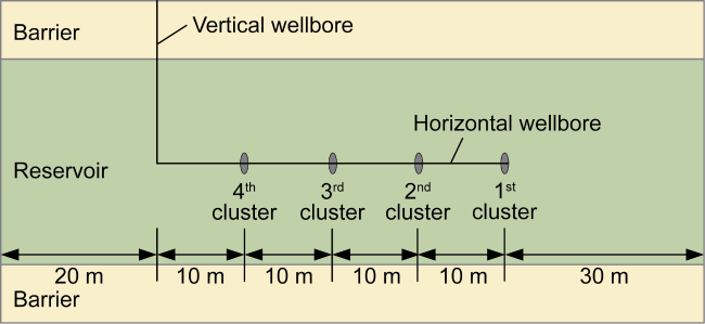
Fig. 9. Fracture initiation and propagation model. |
The fracture propagation was simulated under two processes: conventional fracturing and intra-fracture temporary plugging fracturing. Case 1 involves 4 clusters of fractures in conventional fracturing process without adding temporary plugging agent. Case 2 involves 4 clusters of fractures in intra-fracture temporary plugging fracturing process with the addition of temporary plugging agent. In Case 2, the hole size was set as 6 mm to simulate intra-fracture temporary plugging and pressure boosting, and the hole drag was increased by about 5 MPa according the calculation. The simulation input parameters are as follows: displacement of 4 m3/min, 4 fracture clusters, cluster spacing of 10 m, fracturing fluid viscosity of 100 mPa·s, hydraulic perforation size of 20 mm for Case 1 and 6 mm for Case 2, and 6 perforations per cluster. The physical properties and rock-mechanical parameters of reservoir and barrier are listed in Table 3 .
Table 3. Physical properties and rock-mechanical parameters of reservoir and barrier |
| Formation | Vertical stress/ MPa | Maximum horizontal principal stress/MPa | Minimum horizontal principal stress/MPa | Elastic modulus/ GPa | Poisson's ratio | Compressive strength/MPa | Tensile strength/ MPa | Fracture toughness/ (MPa·m0.5) | Porosity/ % | Permeability/ 10−3 μm2 |
|---|---|---|---|---|---|---|---|---|---|---|
| Barrier | 37.11 | 31.54 | 28.57 | 26.70 | 0.18 | 120.42 | 4.80 | 5 | 2.0 | 0.03 |
| Reservoir | 33.37 | 28.36 | 25.69 | 11.52 | 0.19 | 64.24 | 3.34 | 3 | 12.8 | 2.30 |
The simulation results (Figs. 10 and 11 ) show that, in case of four-cluster perforation without temporary plugging, the first and third clusters of fractures propagate sufficiently, while the second and fourth clusters of fractures do not form effective fractures due to stress shadow suppression. After temporary plugging, all four clusters of fractures form effective fractures, but the first and fourth clusters of fractures shift and propagate outward due to stress interference. To allow all clusters to form effective propped fractures and ensure the post-fracturing effect, the intra-fracture temporary plugging technology can be further adopted to promote the uniform propagation of all clusters of fractures. Moreover, the temporary plugging timing and the dosage of temporary plugging agent can be optimized depending on actual applications.
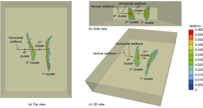
Fig. 10. Numerical simulation results of multi-cluster fracture propagation without temporary plugging. |
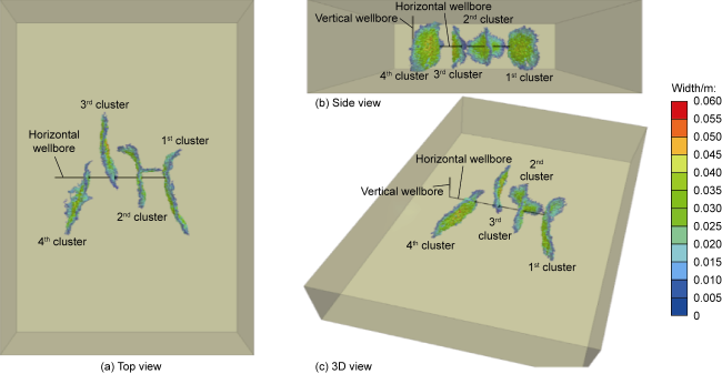
Fig. 11. Numerical simulation results of multi-cluster fracture propagation with temporary plugging. |
2.2. Optimization of sidetracking horizontal well fracturing tool and process
For flexible sidetracking horizontal well with small wellbore curvature radius (2-4 m), conventional jetting tool with large size cannot pass through the build section when open hole completion mode is adopted. Therefore, a new type of hydraulic ejector was designed (Fig. 12 ), with a length of 150 mm, 6 holes (5 mm in size), and a phase angle of 60°. One end of the ejector is designed with a universal joint structure, in which a dynamic sealing structure is adopted at the fitting surface. This sealing structure has a sealing pressure exceeding 50 MPa, and can smoothly pass through the build section to the open hole section of the sidetracking horizontal well, while meeting the seal requirements under fracturing conditions. A circular arc transition is used inside the joining part between the ejector body and the universal joint to reduce the frictional resistance caused by the sudden change in structural size when liquid flows through. Meanwhile, antifriction materials are sprayed on the liquid passage, extending the service life of the ejector by more than 30%. In addition, a centralizing structure is equipped to effectively reduce the energy loss caused by vibration during jetting, thus improving the effectiveness of jetting.
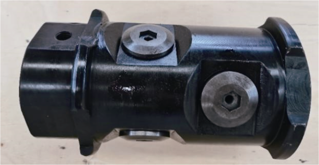
Fig. 12. The new hydraulic ejector. |
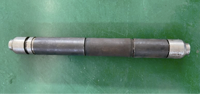
Since the curvature radius of ultrashort-radius sidetracked hole is less than 4 m, a conventional packer with large rigidity cannot smoothly pass through the build section to the designed setting position. To ensure the smooth throughput in sidetracked hole [19], the conventional expanding open hole packer was optimized structurally. Similar to the flexible drill pipe transmission structure, the upper and lower connection joints of the packer all adopt ball head design (Fig. 13 ). The mandrel of the packer is made of titanium alloy. When passing through the build section, the packer body can be elastically bent within a range of 7°, forming a flexible expanding open hole packer. This packer has a length of 620 mm, the outer diameter of 95 mm, the pressure resistance of 50 MPa, and the minimum allowable throughput curvature radius of 1.8 m. During hydraulic fracturing, the flexible expanding open hole packer is inserted deep into the horizontal section, and the designed setting point is more than 10 m away from the original wellbore to avoid the initiation of old fractures. The distance between the first jet perforation position and the original wellbore is increased from 10 m to 15 m, reducing the risk of connection of propagated fractures to old fractures.
Fig. 13. The flexible expanding open hole packer. |
By means of laboratory experiments and numerical simulation, combined with physical property characteristics of target reservoirs, the hydraulic jet pumping rate is optimized as 1.0-1.5 m3/min, the nozzle jet velocity as 142-198 m/s, and the sand concentration of jetting fluid as 6%-10% [20⇓-22]. During field fracturing operations, the hydraulic jet string is run in hole to conduct hydraulic jetting at the optimized perforation position, forming a mechanical weak surface at the jetting position to induce hydraulic fracture initiation and propagation. The hydraulic jetting string can be lifted in turn to achieve hydraulic jetting at multiple perforation positions. Then, after the jetting is completed, the hydraulic jetting string is tripped out, and the fracturing string is run in hole for fracturing process. The fracturing string is composed of new hydraulic ejector, flexible expanding open hole packer, flexible drill/composite pipe, and hydraulic safety joint, etc., from bottom to top. During the fracturing process, the intra-fracture temporary plugging agent is added to increase the net pressure in the fracture, facilitating the uniform propagation of multi-cluster fractures and the opening of natural fractures [23⇓-25].
3. Field application
Considering the difficult production of remaining oil and gas resources in lateral deep parts of low-permeability reservoirs, a field test of flexible sidetracking horizontal well stimulation was conducted in the flexible sidetracking demonstration area of ultra-low permeability reservoir in the Ansai Oilfield of Changqing.
3.1. Difficulties and countermeasures in stimulation
The Chang 6 oil reservoir in the Ansai Oilfield of Changqing is a typical ultra-low permeability reservoir, with an average buried depth of 1 365 m, a formation temperature of 44.5 °C, an initial formation pressure of 9.13 MPa, a saturation pressure of 6.23 MPa, a formation-saturation pressure difference of 2.90 MPa, and a pressure coefficient of 0.7-0.8. The reservoir thickness, porosity and permeability are 2-10 m, 8%-14% and (0.2-1.0)×10−3 μm2, respectively, and the oil saturation is 40%-60%. The oil reservoir has been developed by water injection for more than 30 years. Currently, the oil reservoir is being developed by a row well pattern, with a well array spacing of 160 m×200 m, the reserves recovery percent of 16.86%, and the composite water cut of 72.5%. It is in the middle-late development stage, facing the challenges such as low well productivity and difficult establishment of an effective pressure system. In this context, the flexible sidetracking horizontal well stimulation technology is designed to reduce the oil/water well array spacing, establish a pressure displacement system, realize pressure conduction, and ultimately enhance the production of low-yield and low-efficiency wells [26-27].
The observation of cores taken from inspection wells such as An 201 and Bai 209 shows that the cores are slightly washed at 25 m from the water line, and not washed beyond 40 m. The vertical washing thickness is less than 1 m. The injected water rushes along natural fractures, and remaining oil is enriched in a large area both horizontally and vertically. Based on remaining oil distribution law and the characteristics of flexible sidetracking horizontal well stimulation technology, ultra-short radius horizontal wells are deployed: (1) in the blocks with lateral local massive remaining oil distributed on the sides of fractures, to effectively improve the control degree of reserves and the well productivity; and (2) in the ultra-low permeability blocks characterized by large well array spacing, ineffective long-term waterflooding, and poor adaptability of basic well pattern, where the reserves recovery percent is less than 6%, the recovery rate is less than 4%, and the composite water cut is less than 50%, to reduce well array spacing, and quickly establish an effective pressure displacement system, thereby improving the stimulation effect and the well productivity.
3.2. Optimization design of sidetracking horizontal well and fracturing
According to the characteristic of remaining oil enrichment on the sides of fractures in low-permeability reservoirs, flexible sidetracking horizontal wells can directly communicate with the remaining oil enriched area. Therefore, accurately evaluating the distribution of remaining oil to guide the determination of sidetracking horizontal well azimuth and length is an important prerequisite for improving post-fracturing production and achieving efficient recovery of remaining oil [28⇓-30]. Numerical simulation was conducted on the remaining oil distribution in the demonstration area. First, based on a great deal of actual data, the reservoir numerical simulation software was used to build a geological model for the injection-production well group determined according to the location of the target well. Then, based on well logging and primary fracturing data, the model was refined by setting the parameters such as permeability, porosity and initial fracture. Finally, a history matching was conducted on the production performance of the well group to determine the remaining oil distribution of the well group, and the sidetracking horizontal well azimuth was optimized based on the remaining oil distribution results. In this case, the remaining oil is mainly enriched within 110 m range of the minimum horizontal principal stress of the target well, the oil saturation is 42%-57%, and the remaining oil saturation is higher in the upper layer. Therefore, the optimized sidetracking horizontal well azimuth is the minimum horizontal principal stress azimuth, that is, the azimuth is 337° or 157°. Based on the distribution of remaining oil saturation, the length of the sidetracking horizontal well is further optimized: if the sidetracking horizontal well is drilled along the 337° azimuth, the length of the horizontal section should be limited to 50 m to prevent from communicating the waterflooding front; if the sidetracking horizontal well is drilled along the 157° azimuth, the length of the horizontal section can be increased to 100 m.
3.3. Field implementation and application effect
From 2020 to 2021, the flexible sidetracking stimulation technology was successfully applied in 10 wells of the Ansai Oilfield of Changqing. The length of sidetracked horizontal sections is 24.0-43.3 m, the azimuth of sidetracking horizontal wells is controlled at 328°-24° or 155°-192°, the fracture spacing is 9-12 m, the number of clusters is 2-4, the pumping rate is 3-4 m3/min, the pumped-in fluid volume is 300-400 m3, and the sand addition volume of single fracture is 15-25 m3 (Table 4 ). By the end of December 2024, the incremental oil of 10 wells after fracturing was 1 172.0 t individually, and 11 719.6 t in total, indicating good results (Table 5 ). Due to the low cost of the technology, the break-even point of cumulative incremental oil per well is 400 t ($45/bbl), proving that the technology is economically beneficial.
Table 4. Operation parameters of flexible sidetracking horizontal well stimulation technology |
| Well | Length of sidetracked horizontal section/m | Sidetracking azimuth | Formation pressure before stimulation/% | Number of fracturing clusters | Pumping rate/ (m3·min−1) | Pumped- in fluid volume/m3 | Pumped-in proppant volume/m3 | Temporary plugging agent |
|---|---|---|---|---|---|---|---|---|
| PJ49-16 | 24.0 | 185° | 103.5 | 2 | 4 | 301.2 | 50.4 | 2-stage temporary plugging, 300 kg per stage |
| PJ48-17 | 42.0 | 6°-24° | 112.6 | 4 | 4 | 411.1 | 70.0 | 2-stage temporary plugging, 300 kg per stage |
| P39-41 | 29.6 | 347°-358° | 92.7 | 3 | 4 | 399.0 | 60.7 | 2-stage temporary plugging, 100 kg per stage |
| PJ21-07 | 35.0 | 157°-192° | 75.8 | 3 | 4 | 397.0 | 64.8 | 2-stage temporary plugging, 100 kg per stage |
| PJ13-12 | 28.5 | 337°-342° | 65.0 | 3 | 4 | 396.8 | 54.5 | 2-stage temporary plugging, 100 kg per stage |
| PJ23-11 | 32.5 | 355°-7° | 39.7 | 3 | 4 | 310.0 | 54.5 | 2-stage temporary plugging, 100 kg per stage |
| PJ11-17 | 43.3 | 166°-172° | 44.5 | 3 | 4 | 327.4 | 52.1 | 2-stage temporary plugging, 100 kg per stage |
| PJ17-14 | 34.5 | 328°-343° | 84.5 | 3 | 4 | 313.4 | 50.7 | 2-stage temporary plugging, 100 kg per stage |
| WJ41-0261 | 26.5 | 337° | 87.2 | 3 | 3 | 346.0 | 54.2 | 2-stage temporary plugging, 300 kg per stage |
| W399-101 | 30.9 | 80°-92° | 123.1 | 3 | 3 | 313.0 | 50.4 | 2-stage temporary plugging, 300 kg per stage |
Table 5. Application effect of flexible sidetracking horizontal well stimulation technology |
| Well | Early stage after fracturing | December 2024 | Production days/d | Stage incremental oil/t | Incremental oil per well/(t·d−1) | ||
|---|---|---|---|---|---|---|---|
| Liquid production/ (m3·d−1) | Oil production/ (t·d−1) | Liquid production/ (m3·d−1) | Oil production/ (t·d−1) | ||||
| PJ49-16 | 3.99 | 1.20 | 1.21 | 0.30 | 1 396 | 773.8 | 0.55 |
| PJ48-17 | 3.99 | 2.26 | 2.51 | 1.37 | 1 383 | 2 031.2 | 1.47 |
| P39-41 | 4.04 | 1.74 | 0.44 | 0.27 | 1 253 | 1 238.8 | 0.99 |
| PJ21-07 | 2.13 | 0.99 | 0.85 | 0.41 | 1 202 | 557.6 | 0.46 |
| PJ13-12 | 3.98 | 1.42 | 2.43 | 1.73 | 1 196 | 1 122. 5 | 0.93 |
| PJ23-11 | 3.57 | 0.74 | 0.54 | 0.39 | 1 185 | 422.7 | 0.36 |
| PJ11-17 | 2.83 | 1.80 | 1.23 | 0.71 | 1 160 | 733.7 | 0.63 |
| PJ17-14 | 2.46 | 1.32 | 1.93 | 1.58 | 1 157 | 1 626.0 | 1.41 |
| WJ41-0261 | 4.95 | 3.55 | 1.12 | 0.73 | 1 610 | 2 245.7 | 1.40 |
| W399-101 | 4.25 | 1.20 | 1.48 | 0.79 | 1 560 | 967.6 | 0.62 |
| Average | 3.62 | 1.62 | 1.37 | 0.83 | 1 310 | 1 172.0 | 0.88 |
Based on field operation data, the hydraulic fracturing software was used to perform net pressure fitting for six wells (PJ49-16, PJ48-17, PJ39-41, PJ21-07, PJ13-12 and PJ23-11). The fitting results show that after temporary plugging, the net pressure in the fracture is increased by 4-5 MPa, the fracture height is 15-20 m, and the fracture half-length is 70-80 m.
Post-fracturing comparative analysis indicates two key factors deciding the post-fracturing production of sidetracking horizontal wells. One factor is the azimuth of sidetracked hole. For Well W399-101, the length of sidetracked horizontal section is 30.9 m, and the angle between the sidetracking azimuth and the minimum principal stress direction is 65°-77°. For Well WJ41-0261, the length of sidetracked horizontal section is 26.5 m, and the angle between the sidetracking azimuth and the minimum principal stress direction is 0°. For the two wells, the proppant consumption is 50.4 m3 and 54.2 m3 respectively, and the proppant volume of single cluster is 16.8 m3 and 18.1 m3 respectively, with a difference of about 7.7%. Similar results are found for other reservoirs and operation parameters such as horizon, cluster number, pumping rate, fracturing process, fracturing fluid type and proppant grain size. By the end of 2024, the incremental oil of the two wells was 967.6 t and 2 245.7 t respectively, with a difference of 132.3%. It is believed that a smaller angle between the sidetracking horizontal well azimuth and the minimum principal stress direction is more conducive to communicating the remaining oil and improving the stimulation effect. The other factor is the length of sidetracked horizontal section and the scale of effective stimulation. For Well PJ48-17, the length of sidetracked horizontal section is 42 m, the number of clusters is 4, the proppant volume is 70.0 m3, and the proppant volume of single cluster is 17.5 m3. For Well PJ49-16, these parameters are 24 m, 2, 50.4 m3 and 25.2 m3, respectively. Similar results are obtained for other reservoirs and operation parameters such as horizon, pumping rate, fracturing process, fracturing fluid type and proppant grain size. By the end of 2024, the incremental oil of the two wells was 2 021.2 t and 773.8 t, respectively. Obviously, the longer the sidetracked horizontal section and the more the effective fractures, the higher the post-fracturing initial production and the cumulative production are.
4. Conclusions
The flexible sidetracking horizontal well stimulation technology is an effective option to improve the development effect of low-permeability mature fields. Specifically, depending on the remaining oil distribution in mature fields, low-cost sidetracking is conducted in old wells. Then, hydraulic jetting is used to induce initiation of fractures. Finally, the tubing string is run in hole to for fracturing the sidetracked hole. The field test results show that the flexible sidetracking horizontal well stimulation technology is feasible, well-performed, and promising for application.
Considering the current development status of low-permeability mature fields in China, more efforts will be devoted to further improve the length of sidetracked horizontal section and the accuracy of staged stimulation, thereby increasing the number of fractures and the stimulated reservoir volume. In this way, the remaining oil enriched area will be efficiently stimulated, and the post-fracturing production and economic benefit of flexible sidetracking horizontal wells will be improved.