

Introduction
Lost circulation refers to the phenomenon by which a large amount of drilling fluid flows into the formation during the drilling process. Lost circulation not only causes significant loss of drilling fluid and a prolonged drilling cycle but also may lead to complex situations such as borehole collapse, blowout and drill pipe sticking, and even borehole abandonment if not handled properly[1]. According to statistics, 26% of oil and gas wells worldwide have lost circulation problems, and the cost of lost circulation control is up to $2 billion annually [2-3]. From 2017 to 2019, the average annual time loss caused by lost circulation accounted for about 70% of the total time loss of drilling accidents, with the direct economic loss exceeding 4 billion yuan per year of CNPC (China National Petroleum Corporation) [4]. For drilling operations in the Gulf of Mexico, 12% of non-productive time is caused by lost circulation; at least 45% of wells in the Rumaila oilfield in Iraq experienced severe or total losses[5⇓-7]. As oil and gas exploration and development expands into deep, ultra-deep, and offshore deepwater, geological conditions become more complex, and the lost circulation problem becomes more prominent.
In order to effectively control and eliminate lost circulation problems, scholars at home and abroad have successively proposed optimization rules to select particle size distribution of lost circulation material (LCM) for porous and fractured formations [8]. The main plugging rules applicable to porous formation include the Abram’s law [9], Ideal Packing Theory [10⇓-12], and Vickers’s law [13], etc. The main plugging rules applicable to fractured formation are the D50 rule [14], Mortadha’s law [15] and Omid bimodal criteria [16]. These rules all propose the matching relationship between the particle size of plugging particles and formation pores or fractures from the experimental point of view and form methods for optimizing the size distribution of plugging particles. However, the formation mechanism of the plugging zone remains unclear, and there are still problems such as insufficient pressure-bearing capacity and the low success rate of primary plugging.
In this study, a plugging experimental device and granular material mechanics were applied to study the formation process of the plugging zone in fractured formations, analyze the composition and ratios of different sizes of particles in the plugging zone, reveal the essence of the formation of the plugging zone and the driving force for its destruction, and form the optimal selection rules of plugging particles. Novel LCMs were designed and formulated according to the optimal selection rules established to optimize the lost circulation control system. The research results can provide theoretical and technical support for dealing with lost circulation in fractured formations.
1. Plugging zone formation process
A visualized plugging experimental device and the Particle Flow Code (PFC) were used to simulate the formation process of the plugging zone in fractured formations. The visualized experimental system is shown in Fig. 1 .
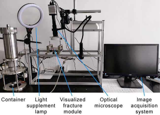
Fig. 1. Visualized plugging experimental device. |
During the plugging zone formation process, the interparticle contact force transfers along a chain-like path (i.e., force chain) in the lost circulation control system, which undergoes a multi-scale structural change from particle to force chain to plugging zone [17]. Macroscopically, it is manifested as a transition from a flow-like state to a solid-like state. According to the state of force chains between plugging particles, the flow regime of the lost circulation control system can be classified as inertial flow, elastic flow and quasi-static flow [18-19].
The inertial flow is at the early formation stage of the plugging zone. When the plugging particles enter the fracture of the lost circulation formation, they migrate in a fluid state under the action of the pressure differential. As shown in Fig. 2 , as the particles continue accumulating in the fracture, the particles collide frequently and transfer momentum. At this time, a stable force chain cannot be formed between the plugging particles, and this state is inertial flow.
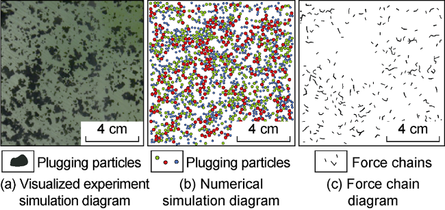
Fig. 2. Visualized experiment and numerical simulation of inertial flow. |
The elastic flow forms in the middle formation stage of the plugging zone. As shown in Fig. 3 , with further accumulation of particles in the fracture, a relatively stable force chain is generated locally in the plugging zone, and the flow state of plugging particles changes from inertial flow to elastic flow. At this time, although relatively stable force chains are formed locally in the plugging zone, most of them are still weak force chains, and there are still many particles not in contact with other particles. Moreover, the particles are subject to a high shear rate and violent collisions. In weak force chains, the particles are in slight contact with very limited deformation, and a tiny shear stress can break the weak force chains (Fig. 4 ).
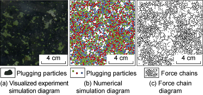
Fig. 3. Visualized experiment and numerical simulation of elastic flow. |
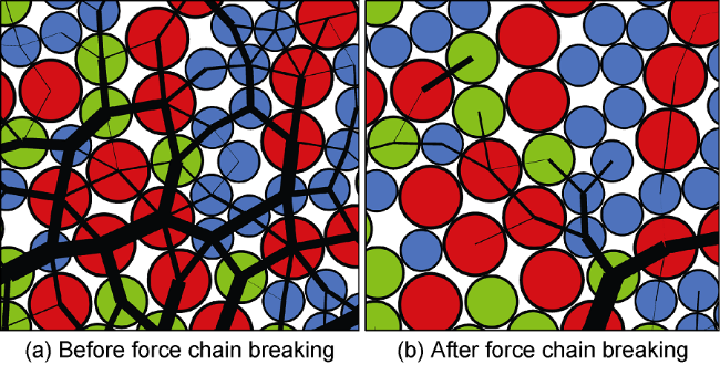
Fig. 4. Migration of local plugging particles and evolution of force chain of elastic flow in plugging zone (Circles of different colors in the figure represent plugging particles of different sizes, and black lines of different thicknesses represent force chains of different strengths). |
The quasi-static flow appears at the late stage of plugging zone formation. As shown in Fig. 5 , as the particles continue to bridge and accumulate within the fracture, they are squeezed together to form a stable force chain, followed by the formation of a stable plugging zone. At this time, the entire plugging zone can be regarded as a continuous solid, and the contact stress in the force chain is independent of the shear rate, which is called the quasi- static flow. Strong force chains account for a larger proportion in the quasi-static flow. The particles are in a self- locking state and can withstand a certain tangential force.
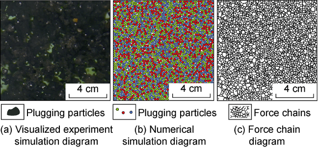
Fig. 5. Visualized experiment and numerical simulation of quasi-static flow. |
The transformation of inertial flow, elastic flow and quasi-static flow during the formation of the plugging zone involves multiple physical processes such as particle collision, adhesion and flow, which are related to the particle size and physical properties (stiffness, viscoelasticity) of plugging particles as well as reservoir stress. Therefore, when preparing the lost circulation controlsystem, the LCM with a suitable particle size distribution and physical properties should be optimally selected according to the characteristics of the formation fractures to achieve the optimal lost circulation control performance.
2. Composition and ratio of plugging particles in plugging zone
2.1. Composition of plugging zone and their functions
Researchers have successively proposed different lost circulation control mechanisms for the functions of plugging particles of different sizes in the plugging zone, including the mechanism of stress cage, fracture-closure stress (FCS), and fracture-propagation pressure (FPR)[20⇓⇓-23]. These mechanisms analyze the mechanical mechanisms of plugging particles of different sizes forming a plugging zone at the mouth, middle part, and tip of the fracture and improving the pressure-bearing capacity of the formation. According to the particle size and function, the plugging particles can be classified as fracture mouth plugging particles, bridging particles and filling particles (Fig. 6 ). The dosage of fracture mouth plugging particles is small. Their main functions are to form a plugging zone near the fracture mouth, develop a sufficient hoop stress around the wellbore, and protect the plugging zone in the fracture from pressure fluctuations. The bridging particles play a decisive role in the success of plugging, mainly forming a bridging plugging zone in the middle part of the fracture and increasing the fracture-closure stress. Filling particles mainly have two functions: (1) filling pores in the plugging zone after the formation of bridge plugging by bridging particles to improve the density of the plugging zone and (2) forming a plugging zone at the tail end of the fracture owing to their small size, isolating the fracture tip, and preventing the generation of induced fractures.
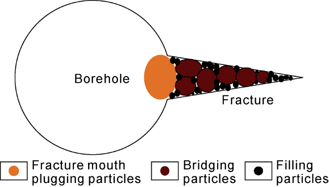
Fig. 6. Composition of plugging particles. |
2.2. Ratio of plugging particles in plugging zone
Assuming that the fracture mouth plugging particles, bridging particles, and filling particles in the plugging zone are spherical particles of relatively the same size, referring to the calculation method in the references [24⇓-26], the Z-φ phase diagram of the plugging particles can be obtained (Fig. 7 ). In the figure, Z is the mechanical coordination number, φ is the particle volume fraction, and X is the entropic compressibility of particles. As shown in Fig. 7 , the Z-φ curves of different entropic compressibilities form a triangular region. If the coordination number and entropic compressibility of plugging particles in the plugging zone fall in the triangular region, the plugging particles can form a plugging zone with a certain pressure-bearing capacity to perform successful loss control. Otherwise, the loss control fails.
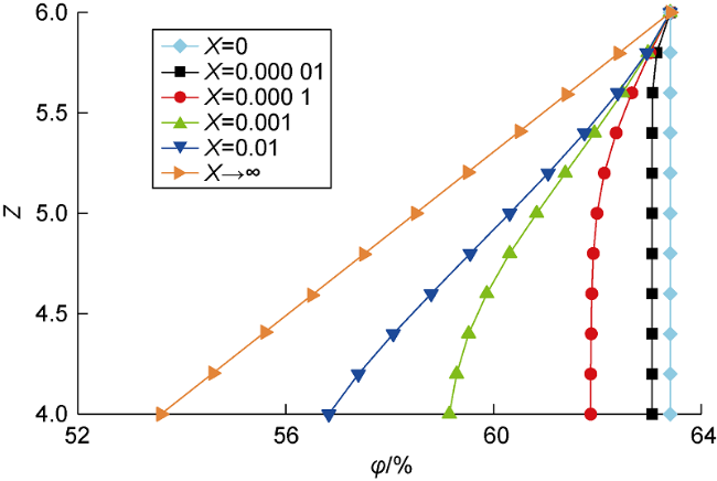
Fig. 7. Z-φ phase diagram of plugging particles. |
When the fracture mouth plugging particles and bridging particles (collectively called coarse particles) in the plugging zone are in the most closely packed state, i.e., when X=0, the volume fraction of coarse particles in the plugging zone is as follows:
${{\varphi }_{\text{c}}}=\varphi \left( X=0,Z \right)=\frac{6}{6+2\sqrt{3}}\text{=}63.4\text{ }\!\!%\!\!\text{ }$
The filling particles fill the pores between the coarse particles and are in a loose accumulation state, i.e., X→∞. At this time, the volume fraction of filling particles in the pores between the coarse particles can be calculated:
${{\varphi }_{\text{f}}}\text{=}\varphi (X\to \infty,Z)\approx \frac{\text{4}}{4+2\sqrt{3}}\text{=}53.6\text{ }\!\!%\!\!\text{ }$
Assuming that the volume of the plugging zone is V, the volume of the pores between coarse particles and that of coarse particles, respectively, are as follows:
${{V}_{\text{cv}}}=\left( 1-{{\varphi }_{\text{c}}} \right)V$
${{V}_{\text{cs}}}={{\varphi }_{\text{c}}}V$
The volume of filling particles is as follows:
${{V}_{\text{fs}}}={{\varphi }_{\text{f}}}{{V}_{\text{cv}}}$
The proportion of filling particles, i.e., the ratio of the volume of filling particles to the total volume of plugging particles, is as follows:
${{\varphi }_{\text{p}}}=\frac{{{V}_{\text{fs}}}}{{{V}_{\text{cs}}}+{{V}_{\text{fs}}}}$
Substituting Eqs. (1)-(5) into Eq. (6), the proportion of filling particles in the lost circulation control system is about 25%, and the total proportion of fracture mouth plugging particles and bridging particles is about 75%.
3. Formation mechanism of plugging zone and driving force for its destruction
3.1. Formation mechanism of plugging zone
The formation of the plugging zone is the transformation process of the LCMs from a non-interacting, non- rigid liquid-like system to an interacting rigid amorphous Jammed solid-state while maintaining the disordered structure of the liquid state. The essence of the formation of the plugging zone is a non-equilibrium Jamming phase transition.
If the purely repulsive part of the interaction is considered only, under a certain formation pressure, there exists a special state point for the volume fraction of the Jamming state particles in the plugging zone, usually called the J-point, when all particles are just in contact, as shown in Fig. 8 . When the volume fraction of plugging particles is lower than that at the J-point, no stable contact is formed between plugging particles. As the volume fraction of plugging particles increases to that at the J-point, the particles become in full contact to form the plugging zone. Along with the progression of the lost circulation control process, the volume fraction of plugging particles further increases, and the particles interact with each other to form a force chain network throughout the system, thus forming a dense solid plugging zone with a certain mechanical stiffness. The volume fraction at the J-point can be calculated as follows:
${{\varphi }_{\text{J}}}\text{=}\frac{{{V}_{\text{cs,J}}}+{{V}_{\text{fs,J}}}}{V}$
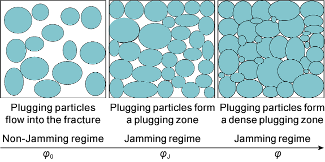
Fig. 8. Schematic diagram of Jamming phase transition of plugging particles. |
For the three-dimensional purely repulsive frictionless spherical particle plugging zone, the Jamming phase diagram of plugging particle system is shown in Fig. 9 a. When the volume fraction of particles is less than that at the J-point, the plugging particle system is in a flow-like state. When the volume fraction of particles is larger than that at the J-point, the plugging particle system is like an amorphous solid, and all particles are self-locked in the force chain and cannot move freely.
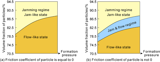
Fig. 9. Jamming phase diagram of plugging particle system. |
In fact, there are many types of particles including rigid particles, elastic particles and fiber particles, with different properties (e.g., friction coefficient, viscoelasticity). Therefore, in the plugging zone formation process, in addition to the pure repulsive force, there are also friction, adhesion and other interactive forces between plugging particles. The interaction forces such as friction and adhesion reduce the volume fraction at the J-point [25], prompting the rapid formation of the plugging zone by the plugging particles in the lost circulation channel, and the J-point becomes a region surrounded by the J-line, as shown in Fig. 9 b. With the increase of friction and adhesion, the volume fraction required for plugging particles to transform from a non-Jamming state to a Jamming state decreases, and the time for the formation of the plugging zone is also shortened. Therefore, when performing lost circulation control operations, gel or resin particles with higher friction coefficients and adhesive properties should be selected to accelerate the formation of the plugging zone and effectively reduce lost circulation of the drilling fluid.
3.2. Driving force for destruction of plugging zone
In comparison to solid materials, the plugging zone composed of plugging particles produces a high nonlinear response under small perturbations. At thermal equilibrium, the internal energy of the solid material system contributes much more to the free energy than entropy, and the structure and properties of the material are mainly determined by the minimum internal energy. However, for plugging particles, the internal energy is much smaller than the product of temperature and entropy, and thus, the structure of the equilibrium state is determined by the maximum value of entropy [27]. The force generated when the entropy of the plugging particle system deviates from the maximum value is the entropic force, and the response of particles to external perturbations is driven by this entropic force [28]. The plugging particles interact with each other by contact forces to form a system. During the formation of the plugging zone, the flow state of the plugging particles changes from inertial and elastic flows to quasi-static flow, entering into a disordered state characterized by the entropy of the particles [29].
The coordination number is the average number of particles in contact with each particle in the plugging particle system. Particles with a coordination number less than 2 do not contribute to the pressure-bearing capacity of the plugging zone. Under a certain porosity condition, the coordination number is mainly influenced by the interparticle friction coefficient and the dimension of formation fractures. The friction coefficient of plugging particles is generally in the range of 0.1-1.0. In this interval, the coordination number of plugging particles decreases significantly with the increase of the friction coefficient [26]. Fig. 10 shows the variation trend of the entropy of plugging particles with the coordination number, and it can be seen that the entropy of plugging particles is negatively correlated with the coordination number. Therefore, when performing lost circulation control operations, LCM with a large friction coefficient should be selected to reach the maximum value of entropy of the plugging particle system so that the plugging zone is in the most stable state.
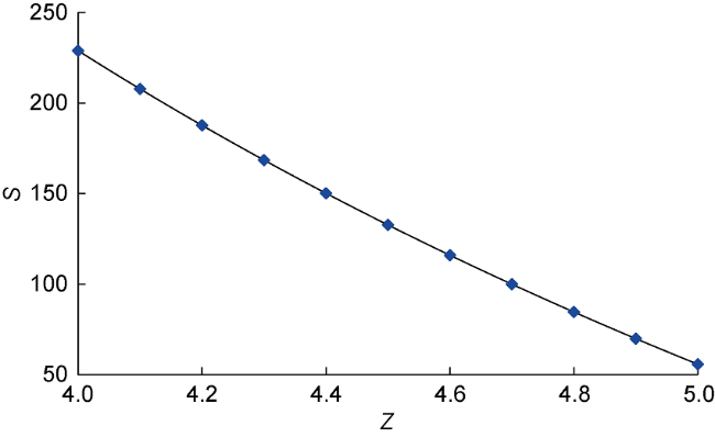
Fig. 10. Variation of entropy of plugging particles with coordination number. |
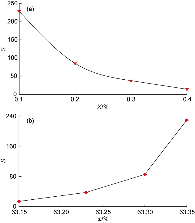
Fig. 11. Variation of entropy of plugging particles with entropic compressibility (a) and particle volume fraction (b). |
4. Optimal selection of LCM and formulation optimization
4.1. Matching particle size and dosage of plugging particles with fracture
Based on extensive optimization experiments of rigid particles, walnut shell particles were optimally selected. A rock sample simulated by metal and a real fractured rock sample (25 mm in diameter and 50 mm in length) were used for pressure-bearing lost circulation control experiments to reveal the matching relationship between the particle size and dosage of plugging particles in the drilling fluid with fracture width.
The Qingdao Tongchun TCP-2 high-temperature and high-pressure lost circulation simulator was used for the tests, and the experimental procedures were as follows: (1) The core was placed in the core holder, and a confining pressure of 1-2 MPa was applied. (2) The plugging particles were added to the container. (3) The upstream and downstream pressures were set with an initial pressure difference of 1 MPa, and the downstream outlet of the core holder was opened after 30 s. (4) The leakage loss at the outlet was recorded, and when the loss was zero, the corresponding pressure was kept for 10 min. If lost circulation occurred again within 10 min, the loss time and leakage loss were recorded; otherwise, the pressure was kept for another 10 min. (5) After 10 min of pressure stabilization, the pressure was increased by 0.5-1.0 MPa. (6) Steps 1-5 were repeated until the plugging failed, and the experiment was then ended.
Table 1. Pressure-bearing capacities of plugging particles of different sizes with dosage of 8% |
| No. | Particle size/mm | Fracture width/mm | Ratio of particle size and fracture width | Pressure-bearing capacity in simulated rock sample/MPa | Pressure-bearing capacity in fractured rock sample/MPa |
|---|---|---|---|---|---|
| 1 | 0.30≤d<0.35 | 0.5 | 0.6≤d/W<0.7 | 11.10 | 12.83 |
| 2 | 0.25≤d<0.30 | 0.5 | 0.5≤d/W<0.6 | 4.97 | 5.65 |
| 3 | 0.20≤d<0.25 | 0.5 | 0.4≤d/W<0.5 | 5.63 | 6.47 |
| 4 | 0.15≤d<0.20 | 0.5 | 0.3≤d/W<0.4 | 9.88 | 10.92 |
| 5 | 0.10≤d<0.15 | 0.5 | 0.2≤d/W<0.3 | 0.82 | 1.31 |

Fig. 12. Plugging effects of plugging particles of different sizes (left: metal simulated rock sample, right: fractured rock sample). |
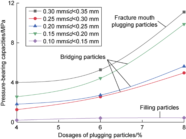
Fig. 13. Pressure-bearing capacities of plugging particles of different sizes and dosages in simulated rock sample. |
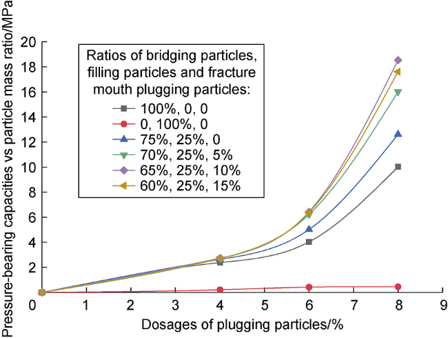
Fig. 14. Pressure-bearing capacities of plugging particles of different formulations and dosages in simulated rock sample. |
Table 2. Pressure-bearing capacities of plugging particles of different formulations with dosage of 8% |
| No. | Fracture Width/mm | Formulations | Pressure-bearing capacity/MPa |
|---|---|---|---|
| 1 | 0.5 | 8% bridging particles (the ratios of bridging particles, filling particles and fracture mouth plugging particles are 100%, 0 and 0) | 10.02 |
| 2 | 0.5 | 8% filling particles (the ratios of bridging particles, filling particles and fracture mouth plugging particles are 0, 100% and 0) | 0 |
| 3 | 0.5 | 6% bridging particles + 2% filling particles (the ratios of bridging particles, filling particles and fracture mouth plugging particles are 75%, 25% and 0) | 12.61 |
| 4 | 0.5 | 5.6% bridging particles + 2% filling particles + 0.4% fracture mouth plugging particles (the ratios of bridging particles, filling particles and fracture mouth plugging particles are 70%, 25% and 5%) | 16.01 |
| 5 | 0.5 | 5.2% bridging particles + 2% filling particles + 0.8% fracture mouth plugging particles (the ratios of bridging particles, filling particles and fracture mouth plugging particles are 65%, 25% and 10%) | 18.53 |
| 6 | 0.5 | 4.8% bridging particles + 2% filling particles + 1.2% fracture mouth plugging particles (the ratios of bridging particles, filling particles and fracture mouth plugging particles are 60%, 25% and 15%) | 17.64 |
4.2. Optimal selection rules of plugging particles
According to the above results on the formation process of the plugging zone, composition and ratio of plugging particles, formation mechanism of the plugging zone and the driving force for its destruction, and pressure-bearing experiments, we propose the following criteria for the optimal selection of plugging particles in fractured formation.
(1) Particle size and ratios of plugging particles: 10% fracture mouth plugging particles (W ≥ d > 2/3 W), 65% bridging particles (2/3 W ≥ d ≥ 1/3 W), and 25% filling particles (d < 1/3 W); i.e., when the particle size distribution fulfills the conditions of W ≥ D90 ≥ 2/3 W and D25 ≥ 1/3 W, a plugging zone with a high pressure-bearing capacity can be formed.
(2) Physical properties of plugging particles: the bridging particles should be materials with large surface friction coefficients and irregular shapes, and the fracture mouth plugging particles and filling particles should be materials with certain viscoelastic properties (rubber, gel, etc.).
4.3. Comparison of pressure-bearing plugging experimental results of plugging particles selected according to criterion proposed in this paper and other criteria
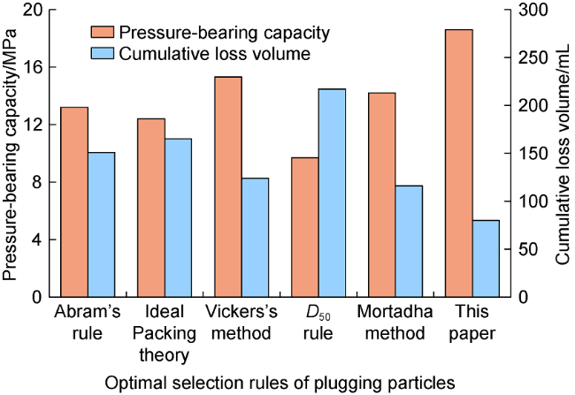
According to the optimal selection criteria of plugging particles for fractured formation proposed in this paper, the bridging particle LCM-A was selected, and the fracture mouth plugging particles and filling particles LCM-B were prepared. LCM-A has a large irregularity, high friction coefficient, and high temperature and pressure resistance. LCM-B can be activated by the high-temperature condition in formation, and it possess a high viscoelasticity, which can be used not only as a filling material to improve the density of the plugging zone but also to seal the fracture mouth or bond the bridging particles. Drilling fluids with lost circulation control systems formulated according to different optimal selection criteria were prepared with a total particle dosage of 8% (Table 3 ).
Table 3. Particle sizes of lost circulation control systems formulated based on different optimal selection criteria |
| No. | Rule | Content | Particle size |
|---|---|---|---|
| 1 | Abram’s rule | D50≥1/3 R | D50=0.5 mm |
| 2 | Ideal Packing theory | The cumulative volume fraction of particles is proportional to the square root of the particle size | D90=1.5 mm |
| 3 | Vickers’s method | D90=Rmax, D75<2/3 Rmax, D50≥1/3 R, D25=1/7 Rave, D10=Rmin | D90=1.5 mm, D75=0.9 mm, D50=0.5 mm, D25=0.2 mm |
| 4 | D50 rule | D50=W | D50=1.5 mm |
| 5 | Mortadha’s method | D50≥3/10 W, D90≥6/5 W | D50=0.45 mm, D90=2 mm |
| 6 | This paper | W≥D90≥2/3 W, D25≥1/3 W | D90=1 mm, D75=0.5 mm, D15 of 0.1-0.3 mm |
Both Vickers’s law and Mortadha’s law suggest lost circulation control formulations containing fracture mouth plugging particles, bridging particles, and filling particles; however, the ratios among the three types of particles are not reasonable. The Abram’s rule and Ideal Packing theory do not specify the ratios and roles of fracture mouth plugging particles, bridging particles, and filling particles that are more suitable for pore plugging. The D50 rule mainly selects fracture mouth plugging particles as the LCM, which is prone to bridging and accumulation at the fracture mouth and difficult to enter the fracture to form an effective plugging zone. The optimal selection criteria of plugging particles proposed in this paper clarify the ratios and roles of fracture mouth plugging particles, bridging particles, and filling particles, optimizing the dosage and particle sizes of plugging particles. The plugging performance of the formulated lost circulation control system and the pressure-bearing capacity of the plugging zone are significantly better than those formulated according to other criteria. Specifically, the accumulated leakage volume can be reduced to 80 mL, and the pressure-bearing capacity is up to 18.6 MPa (Fig. 15 ), which effectively improved fracture plugging effect of the plugging particles.
Fig. 15. Experimental results on pressure-bearing capacities of plugging particles formulated according to different criteria. |
5. Conclusions
The formation process of the plugging zone in the drilling fluid lost circulation channel undergoes multi- scale structural change from particle to force chain to system. Macroscopically, it is manifested as a flow state change process from inertial flow and then elastic flow to quasi-static flow. Jamming phase transition is a non- equilibrium transition process of the plugging particles from a non-interacting non-rigid liquid-like system to a rigid amorphous Jamming solid state, which is the essence of the formation of the plugging zone. The response of particles in the plugging zone to the formation pressure is driven by entropic forces, and the maximum value of entropy depends on the friction coefficient, coordination number and entropic compression of the LCM.
For the design of a drilling fluid lost circulation control system, the particle sizes and ratios of fracture mouth plugging particles, bridging particles, and filling particles should be optimized. The particle size distribution is recommended to meet W ≥ D90 ≥ 2/3 W and D25 ≥ 1/3 W. The physical properties of the plugging particles should also be considered. The bridging particles should be materials with large surface friction coefficients and irregular shapes, and the fracture mouth plugging particles and filling particles should be materials with certain viscoelastic properties for fast and dense plugging.
Nomenclature
d—particle size, m;
D10, D25, D50, D75, D90—particle size corresponding to the cumulative probability of 10%, 25%, 50%, 75%, 90% on the particle size distribution curve, m;
R—pore diameter, m;
Rave—average pore diameter, m;
Rmax—maximum pore diameter, m;
Rmin—minimum pore diameter, m;
S—entropy of plugging particles, J/K.
V—volume of the plugging zone, m3;
Vcs—total volume of fracture mouth plugging particles and bridging particles in the plugging zone, m3;
Vcs,J—total volume of fracture mouth plugging particles and bridging particles in the plugging zone at the J-point, m3;
Vcv—volume of pores between coarse particles (fracture mouth plugging particles and bridging particles) in the plugging zone, m3;
Vfs—volume of filling particles in the plugging zone, m3;
Vfs,J—volume of filling particles in the plugging zone at the J-point, m3;
W—fracture width, m;
X—entropic compression of plugging particles, dimensionless; Z—mechanical coordination number, dimensionless;
φ—volume fraction of plugging particles in the plugging zone, %;
φ0-volume fraction of plugging particles upon entering the lost circulation channel, %;
φc—total volume fraction of fracture mouth plugging particles and bridging particles in the plugging zone, %;
φf—volume fraction of filling particles in the pores between coarse particles (fracture mouth plugging particles and bridging particles), %;
φJ—volume fraction of particles in the plugging zone at the J-point, %;
φp—ratio of filling particles in the plugging system, %.