

Introduction
Shale oil is an important strategic replacement area for future oil resources of China [1]. Shale oil reservoirs are characterized by low porosity, low permeability, with no natural productivity in oil wells. Horizontal wells and large-scale hydraulic fracturing are mostly used for shale oil development [2]. However, the cement sheath of the shale oil well is prone to mechanical damage and interface seal failure under a high-pressure load, which leads to the decline in the wellbore sealing capability, affecting the fracturing effect [3].
Currently, the mechanical and sealing integrity of the cement sheath are generally ensured by optimizing the mechanical properties of the cement sheath [4-5]. Chu et al.[6] analyzed the influence of the change in the internal casing pressure on the mechanical integrity of the cement sheath by establishing an elastic-plastic mechanical model. They found that the cement sheath was plastic yielding during the loading stage, which caused interface debonding and micro-annulus problems during the unloading stage. In addition to the plastic yielding, Liu et al. found that the cement sheath was easily affected by fracturing loads, resulting in tensile and mechanical integrity failures. A cement sheath with low elastic modulus and high Poisson's ratio can effectively avoid yield failure and reduce the risk of micro-annulus [7-8]. Li et al. [9] established a theoretical model to evaluate the interface sealing integrity of the cement sheath under fracturing loads. They found that the Poisson's ratio of the cement sheath had a nonlinear effect on the interface crack length. Increasing elastic modulus of the cement sheath was beneficial in shortening the interface crack length. The study by Fan et al. [5] also pointed out that improving elastic modulus and bonding strength of the cement sheath was beneficial in shortening the propagation length of the interface crack. Wang et al. [10] found that elastic modulus of the cement sheath had a nonlinear effect on the interface crack width, which first increased and then decreased.
Different failure modes of cement sheath have different requirements for the mechanical property parameters of the cement sheath. A reasonable design of the mechanical property parameters was the key to ensuring the mechanical integrity of the cement sheath and the sealing integrity of the interface. To solve the above problems, based on the elastic-plastic model of the cement sheath under three-dimensional stress and the stress field model of the interface crack, by comprehensively considering the failure modes of the cement sheath tensile failure, plastic yield, interface crack propagation along the interface, and interface crack zigzag propagation, a wellbore seal evaluation method and design method for the mechanical properties of the cement sheath were established. Using this method, an analysis of wellbore seal failure under fracturing conditions was conducted, taking the GD horizontal well of shale oil in Dagang Oilfield as an example. The influence rules of cement sheath strength, elastic modulus, and Poisson's ratio on different failure modes were studied, and a quantitative index of mechanical properties was proposed to ensure the mechanical and sealing integrity of the cement sheath during fracturing of the GD Well.
1. Stress analysis of wellbore cement sheath
1.1. Stress analysis of elastic-plastic cement sheath
It is assumed that the casing is centered, casing and formation are homogeneous elastomers, and cement sheath is a homogeneous elastoplastic material. The tensile and compressive stresses are defined as positive and negative, respectively, and the stress state of the cement sheath during fracturing is considered the superposition of the stress change caused by the fracturing load on the initial stress state [11].
1.1.1. Stress and displacement analysis of elastic-plastic cement sheath
During fracturing, the cement sheath is subjected to radial (σr), circumferential (σθ), and axial (σz) stresses. Among them, the radial stress is significantly higher than the circumferential stress, and the axial stress lies be-tween the radial and circumferential stresses, as shown in Fig. 1 .
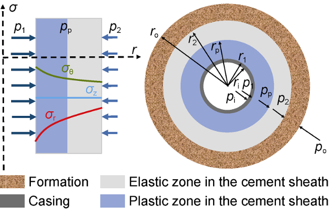
Fig. 1. Schematic of the three-dimensional stress and elastic-plastic model of the cement sheath. |
Considering the value and distribution law of the three-dimensional stress distribution of the wellbore cement sheath, an elastic-plastic mechanical model of the cement sheath is established based on the twin-shear unified strength theory (Eq. (1)) [12] as the yield criterion.
$\frac{1}{\alpha }{{\sigma }_{\text{r}}}-\frac{1}{1+b}\left( b{{\sigma }_{\text{z}}}+{{\sigma }_{\theta }} \right)\text{=}{{\sigma }_{\text{c}}}$
To simplify the derivation process, we consider ${{\sigma }_{\text{z}}}=$ $\left( {{\sigma }_{\text{r}}}+{{\sigma }_{\theta }} \right)/2$. Meanwhile, the stress components of the cement sheath in the radial and circumferential directions satisfy the following equilibrium equation:
$\frac{\text{d}{{\sigma }_{\text{r}}}}{\text{d}r}+\frac{{{\sigma }_{\text{r}}}-{{\sigma }_{\theta }}}{r}=0$
By combining Eq. (1) and Eq. (2), and introducing boundary conditions $r=r_{1}^{{}}$and ${{\sigma }_{\text{r}}}=-{{p}_{1}}$, the stress distribution expression of the plastic zone of the cement sheath is obtained as:
$\left\{ \begin{align} & {{\sigma }_{\text{r}}}=-{{\left( \frac{{{r}_{1}}}{r} \right)}^{M}}\left( {{p}_{1}}+\frac{\alpha {{\sigma }_{\text{c}}}}{1-\alpha } \right)+\frac{\alpha }{1-\alpha }{{\sigma }_{\text{c}}} \\ & {{\sigma }_{\theta }}=-N{{\left( \frac{{{r}_{1}}}{r} \right)}^{M}}\left( {{p}_{1}}+\frac{\alpha {{\sigma }_{\text{c}}}}{1-\alpha } \right)+\frac{\alpha }{1-\alpha }{{\sigma }_{\text{c}}} \\ \end{align} \right.$
where $M=\frac{2+2b-2b\alpha -2\alpha }{2+2b-b\alpha }$ $N=\frac{2\alpha +b\alpha }{2+2b-b\alpha }$
From the above expressions, the contact pressure at the outer boundary of the cement sheath in the plastic zone can be obtained as:
${{p}_{\text{p}}}={{\left( \frac{{{r}_{1}}}{{{r}_{\text{p}}}} \right)}^{M}}\left( {{p}_{1}}+\frac{\alpha {{\sigma }_{\text{c}}}}{1-\alpha } \right)-\frac{\alpha }{1-\alpha }{{\sigma }_{\text{c}}}$
Ignoring the plastic volume strain, according to the law of volume elasticity, the geometric equation, and the equilibrium equation (Eq. (2)), the displacement expression of the plastic zone of the cement sheath can be obtained by integration:
${{u}_{\text{cp}}}=\frac{\left( 1+{{\nu }_{\text{c}}} \right)\left( 1-2{{\nu }_{\text{c}}} \right)}{{{E}_{\text{c}}}}\left[ \frac{\alpha {{\sigma }_{\text{c}}}}{1-\alpha }r- \right.$$\left. \left( {{p}_{1}}+\frac{\alpha {{\sigma }_{\text{c}}}}{1-\alpha } \right)r_{1}^{M}{{r}^{N}} \right]+\frac{K}{r}$
The stress and displacement of the elastic zone of the cement sheath, casing, and formation can be characterized by the Lame formula and displacement formula in the thick-walled cylinder theory of elastic mechanics, as shown in Eq. (6) and Eq. (7):
$\left\{ \begin{align} & {{\sigma }_{\text{r}}}=\frac{R_{\text{i}}^{2}{{p}_{\text{in}}}-R_{\text{o}}^{2}{{p}_{\text{out}}}}{R_{\text{o}}^{2}-R_{\text{i}}^{\text{2}}}-\frac{R_{\text{i}}^{2}R_{\text{o}}^{2}\left( {{p}_{\text{in}}}-{{p}_{\text{out}}} \right)}{\left( R_{\text{o}}^{\text{2}}-R_{\text{i}}^{\text{2}} \right){{R}^{2}}} \\ & {{\sigma }_{\theta }}=\frac{R_{\text{i}}^{2}{{p}_{\text{in}}}-R_{\text{o}}^{2}{{p}_{\text{out}}}}{R_{\text{o}}^{2}-R_{\text{i}}^{\text{2}}}+\frac{R_{\text{i}}^{\text{2}}R_{\text{o}}^{\text{2}}\left( {{p}_{\text{in}}}-{{p}_{\text{out}}} \right)}{\left( R_{\text{o}}^{2}-R_{\text{i}}^{\text{2}} \right){{R}^{2}}} \\ \end{align} \right.$
$u=\frac{1-\nu }{E}\frac{\left( R_{\text{i}}^{2}{{p}_{\text{in}}}-R_{\text{o}}^{2}{{p}_{\text{out}}} \right)R}{R_{\text{o}}^{2}-R_{\text{i}}^{2}}+\frac{1+\nu }{E}\frac{R_{\text{i}}^{2}R_{\text{o}}^{2}\left( {{p}_{\text{in}}}-{{p}_{\text{out}}} \right)}{\left( R_{\text{o}}^{2}-R_{\text{i}}^{2} \right)R}$
At the same time, since the contact pressure between the inner wall of the cement sheath in elastic zone and the outer wall of the cement sheath in plastic zone is equal, the contact pressure on the outer wall of elastic zone of cement sheath can be expressed as:
${{p}_{\text{2}}}=\frac{\left[ \left( 1-\alpha +b-\alpha b \right)r_{\text{p}}^{2}+ \right.\left. \left( 1+\alpha +b \right)r_{2}^{2} \right]{{p}_{\text{p}}}}{r_{2}^{2}\left( 2+2b-\alpha b \right)}-$ $\frac{\alpha \left( 1+b \right)\left( r_{2}^{2}-r_{\text{p}}^{2} \right){{\sigma }_{\text{c}}}}{r_{2}^{2}\left( 2+2b-\alpha b \right)}$
1.1.2. Solution of the elastic-plastic model of cement sheath
Considering the equal displacement at the contact surface of the casing-cement sheath-formation combination, which is assumed as continuous condition, and combining with Eq. (4) and Eq. (8), the following equations are obtained:
$\left\{ \begin{align} & {{u}_{\text{so}}}={{u}_{\text{cpi}}} \\ & {{u}_{\text{cpo}}}={{u}_{\text{cei}}} \\ & {{u}_{\text{ceo}}}={{u}_{\text{fi}}} \\ & {{p}_{\text{p}}}={{\left( \frac{{{r}_{1}}}{{{r}_{\text{p}}}} \right)}^{M}}\left( {{p}_{1}}+\frac{\alpha {{\sigma }_{\text{c}}}}{1-\alpha } \right)-\frac{\alpha }{1-\alpha }{{\sigma }_{\text{c}}} \\ & {{p}_{\text{2}}}=\frac{\left[ \left( 1-\alpha +b-\alpha b \right)r_{\text{p}}^{2}+ \right.\left. \left( 1+\alpha +b \right)r_{2}^{2} \right]{{p}_{\text{p}}}}{r_{2}^{2}\left( 2+2b-\alpha b \right)}- \\ & \frac{\alpha \left( 1+b \right)\left( r_{2}^{2}-r_{\text{p}}^{2} \right){{\sigma }_{\text{c}}}}{r_{2}^{2}\left( 2+2b-\alpha b \right)} \\ \end{align} \right.$
Considering the increment in the internal casing pressure and formation pressure during the fracturing as boundary conditions, the stress state and displacement of any position in the combination can be solved.
1.2. Stress field analysis of cement sheath interface cracks
1.2.1. Characterization of the stress field of interface cracks
Based on the interface fracture mechanics, the stress intensity factor (SIF) method was used to characterize the stress field of the interface crack of the cement sheath under fracturing conditions [13]:
${{K}_{1}}+\text{i}{{K}_{2}}=\frac{\underset{{r}'\to 0}{\mathop{\lim }}\,\left[ \sqrt{2\pi {r}'}\left( {{\sigma }_{\text{y}}}+\text{i}{{\tau }_{\text{xy}}} \right) \right]}{{{\left( {{r}'} \right)}^{\text{i}\varepsilon }}}$
where
$\varepsilon =\frac{1}{2}\ln \frac{\frac{3-4{{\nu }_{1}}}{{{\mu }_{1}}}+\frac{1}{{{\mu }_{2}}}}{\frac{3-4{{\nu }_{2}}}{{{\mu }_{2}}}+\frac{1}{{{\mu }_{1}}}}$
where the subscripts 1 and 2 in Eq. (11) represent the materials on the two sides of the interface.
Taking the cement sheath-formation interface as an example, the stress field of the interface crack is shown in Fig. 2 . It is difficult to directly describe multiple loads in the stress field according to Eq. (10). Therefore, the linear superposition method is used to decompose the stress field of the interface crack into an interface stress field affected by the radial stress of the wellbore and interface bonding strength and a fracturing load field affected by the fracturing fluid load.
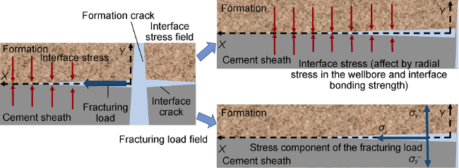
Fig. 2. Schematic diagram of the decomposition model and stress field of the interface crack of the cement sheath- formation interface. |
The interface stress field is numerically equal to the sum of the initial stress at the cement sheath-formation interface, stress increment caused by fracturing and interface bonding strength.
${{\sigma }_{\text{cf}}}\text{=}{{\sigma }_{\text{cf,i}}}+{{\sigma }_{\text{cf,p}}}+{{\sigma }_{\text{b}}}$
The fracturing load field can be divided into two stress components, one parallel and the other perpendicular to the wellbore direction, and its value is related to the fracturing pump pressure, fracturing fluid-column pressure and wellbore friction.
In summary, Eq. (13) can be used to characterize the interface stress field and fracturing load field:
$\left\{ \begin{align} & {{\sigma }_{\text{cf}}}=\frac{{{K}_{\text{1,}\sigma }}+\text{i}{{K}_{\text{2,}\sigma }}}{\sqrt{2\pi {r}'}}{{\left( \frac{{{r}'}}{2a} \right)}^{\text{i}\varepsilon }} \\ & {{\sigma }_{\text{y,p}}}+\text{i}{{\sigma }_{\text{x,p}}}=\frac{{{K}_{\text{1,p}}}+\text{i}{{K}_{\text{2,p}}}}{\sqrt{2\pi {r}'}}{{\left( \frac{{{r}'}}{2a} \right)}^{\text{i}\varepsilon }} \\ \end{align} \right.$
After obtaining the SIFs of the interface stress field and fracturing load field, the SIF of the stress field of the interface crack can be characterized as:
$\left\{ \begin{align} & {{K}_{1}}={{K}_{\text{1,p}}}-{{K}_{\text{1,}\sigma }} \\ & {{K}_{2}}={{K}_{\text{2,p}}}-{{K}_{\text{2,}\sigma }} \\ \end{align} \right.$
1.2.2. Evaluation of propagation length and direction of interface crack
The SIF of the stress field of the interface crack is compared with the critical SIF of the interface crack fracture to judge whether the interface crack propagates[14]:
$K_{1,2}^{*}=\sqrt{{{\left( \frac{{{K}_{1}}}{1.0} \right)}^{2}}+{{\left( \frac{{{K}_{2}}}{1.6} \right)}^{2}}}\ge {{K}_{\text{IC,ini}}}$
The interface crack is affected by the mechanical properties of the cement sheath and formation and the direction of the fracturing load in the crack. Additionally, the interface crack may propagate tortuously, damaging the cement sheath or formation and generating the propagate crack. The maximum circumferential stress is used to analyze the zigzag propagation of cracks and its propagation direction[15]:
$K_{_{I,II}}^{\text{*}}=\frac{\sqrt{K_{1}^{2}+K_{2}^{2}}}{2\cosh \left( \varepsilon \pi \right)}{{B}_{\text{j}}}\left( {{\theta }_{\text{o}}} \right)\ge {{K}_{\text{IJ,ini}}}$
2. Wellbore sealing evaluation method and design method for mechanical properties of cement sheath
2.1. Wellbore sealing evaluation method
The cement sheath has various integrity failure modes under fracturing conditions, including tensile failure, micro-annulus caused by plastic yielding, interface crack propagation along the interface, and interface crack zigzag propagation. The evaluation of the wellbore sealing ability must be analyzed in combination with different cement sheath failure modes. The evaluation process is shown in Fig. 3 .
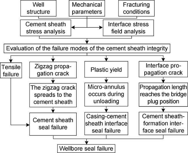
Fig. 3. Flowchart of the evaluation of the wellbore sealing capability. |
2.2. Design method for mechanical properties of cement sheath
If the cement sheath loses its integrity due to fracturing and causes wellbore seal failure, it is necessary to optimize the mechanical properties of the cement sheath according to its failure mode to ensure the cement sheath integrity in the subsequent fracturing wells. The design process is as follows:
3. Model validation and case analysis
3.1. Model validation
Jackson et al. [16] cured the cement sheath in the inner and outer casing, and evaluated the failure of the mechanical integrity of the cement sheath by loading and unloading the internal casing pressure. Chu et al. [6] established an elastic-plastic model of the cement sheath based on the Mohr-Coulomb criterion, and analyzed the elastic-plastic change in the cement sheath and size of the micro-annulus at 55 MPa and 69 MPa combined with the test conditions in the study conducted by Jackson.
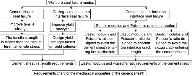
Fig. 4. Flowchart of the design of the mechanical properties of the cement sheath. |
To evaluate the accuracy of the elastic-plastic model established herein and compare the influence of different yield criteria on the calculation results, the same working conditions (55 MPa) as those in the Reference [6] were used for the calculation and discussion. Fig. 5 shows the variation in the elastic-plastic interface radius and radial stress of the cement sheath with the internal casing pressure.
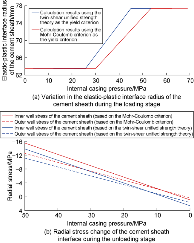
Fig. 5. Variation in the elastic-plastic interface radius and radial stress of the cement sheath with an internal casing pressure. |
In Fig. 5 a, the elastic-plastic interface radius of the cement sheath gradually expands with the increase in the internal casing pressure when the internal casing pressure reaches the yield value of the cement sheath; the cement sheath enters the plastic state earlier when the calculation is performed using the twin-shear unified strength theory as the yield criterion. In Fig. 5 b, the radial stress at the inner and outer walls of the cement sheath decreases as the internal casing pressure decreases. Assuming that the interface bonding strength is 2 MPa when the internal casing pressure drops to 0, the radial stress calculated based on the Mohr-Coulomb criterion is positive (0.89 MPa), indicating tensile stress at the interface. As this stress is lesser than the interface bonding strength, the cement sheath does not display interface debonding behavior. However, the radial tensile stress (2.58 MPa) calculated based on the twin-shear unified strength theory is greater than the bonding strength, indicating that the cement sheath possesses the risk of forming an interface micro-annulus.
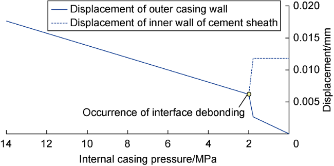
Fig. 6. Size of the micro-annulus at the cement sheath interface during the unloading stage. |
In conclusion, the elastic-plastic state and stress change laws of cement sheath calculated based on different yield criteria are the same, which proves the accuracy of the model. In addition, in the twin-shear unified strength theory, the influence of the intermediate principal stress is considered, which can avoid the results of the conservative analysis of the cement sheath yield and interface micro-annulus.
To analyze the cement sheath interface sealing under fracturing conditions, Bunger et al. [17] designed an evaluation device that regarded an aluminum tube and plexiglass as the casing and simulated formation, respectively, and filled epoxy resin between them as cement sheath. By prefabricating a 3-mm crack at one end of the simulated cement sheath and applying an internal casing pressure of 5 MPa and a fluid load of 10 MPa, the fluid channeling length along the interface was tested. The device sizes and material physical parameters are listed in Table 1 .
Table 1. Device sizes and material physical parameters in a study by Bunger et al. [17] |
| Material | Size/mm | Elastic modulus/GPa | Poisson’s radio |
|---|---|---|---|
| Casing (aluminum) | 14(ID) | 7.0 | 0.32 |
| Simulated cement sheath (epoxy resin) | 17(ID) | 1.0 | 0.38 |
| Simulated formation (plexiglass) | 20(ID) 21(OD) | 3.6 | 0.32 |
Assuming that the interface bonding strength is 2 MPa, based on the above parameters, the interface crack stress field model proposed in this study was used to calculate the channeling length of the interface fluid, the calculation result was 165 mm. Compared with the measured results (175 mm), the error between the two was approximately 5.7 %, which has proved that the calculation result of the model is accurate.
3.2. Case analysis
3.2.1. Overview of shale oil horizontal wells
Well GD in Dagang Oilfield is a shale oil horizontal well. The casing, cement sheath and formation parameters of this well are listed in Table 2 . The yield and tensile strengths of the cement sheath are 23.0 MPa and 4.3 MPa, respectively. The micro-seismic events in the second and third fracturing sections of the well have a high degree of repetition, and their distribution characteristics are primarily identical, indicating that there is a communication channel between the fracturing sections. To analyze the reasons for this phenomenon, the following wellbore sealing analysis is performed.
Table 2. Casing, cement sheath and formation parameters |
| Material | Elastic modulus/GPa | Poisson’s ratio | ID/mm | OD/mm |
|---|---|---|---|---|
| Casing | 210 | 0.30 | 115.52 | 139.7 |
| Cement sheath | 8 | 0.17 | 139.70 | 215.9 |
| Formation | 25 | 0.14 | 215.90 | 2159.0 |
3.2.2. Wellbore sealing analysis
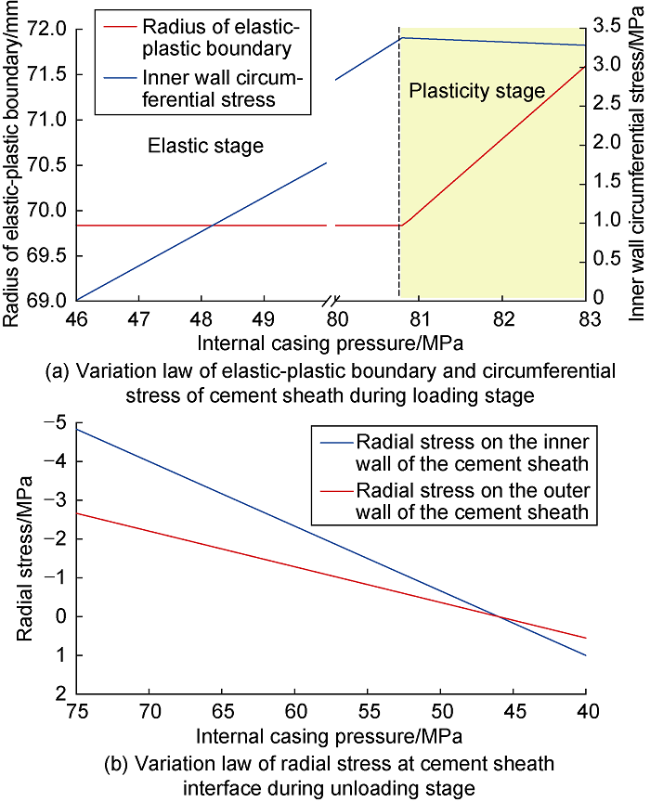
Fig. 7. Variation law of the cement sheath stress during fracturing. |
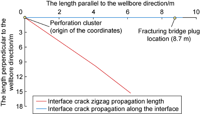
Fig. 8. Lengths of interface crack propagation along the interface and zigzag propagation at the cement sheath-formation interface. |
In conclusion, during fracturing, the cement sheath of Well GD undergoes plastic deformation and a risk of micro-annulus. The cement sheath-formation interface cracks in the second and third fracturing sections are interconnected, which is one of the main reasons for the wellbore sealing failure.
4. Influence of mechanical properties of the cement sheath on wellbore sealing
4.1. Influence of elastic modulus and Poisson's ratio on the cement sheath yield state
Using the parameters listed in Table 2 , keeping the wellbore size, fracturing parameters, and strength of the cement sheath constant, the three-dimensional stress at the inner wall of the cement sheath under the conditions of different elastic moduli and Poisson’s ratios of the cement sheath was calculated. Substitute the results into the left expression in Eq. (1), and subtract the calculation results of the left expression from the right expression (yield strength) to judge the yield state of the cement sheath under the calculation conditions. When the value is equal to 0 (dotted line in the figure), it means that the cement sheath is in the critical state of elastoplasticity; if it is less than 0, it means that the cement sheath has not reached the critical condition of yielding and is still in an elastic state; if it is greater than 0, it means that the cement sheath enters the yield state. The analysis results are shown in Fig. 9 .
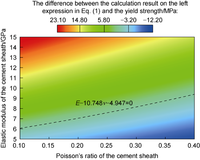
Fig. 9. Influence of elastic modulus and Poisson's ratio on the yield state of the cement sheath. |
Through calculation, it has been found that decreasing elastic modulus of the cement sheath and increasing the Poisson's ratio is beneficial for avoiding the yield of the cement sheath; if the values of Elastic modulus and Poisson's ratio satisfy the condition of $E-10.748\nu -$ $4.947\le 0$ (the area below the dotted line in Fig. 9 ), the cement sheath is always in an elastic state.
4.2. Influence of elastic modulus and Poisson's ratio on the interface crack length
Keeping other parameters constant, change elastic modulus and Poisson's ratio of the cement sheath, and calculate the change law of the interface crack length. The results are shown in Fig. 10 .
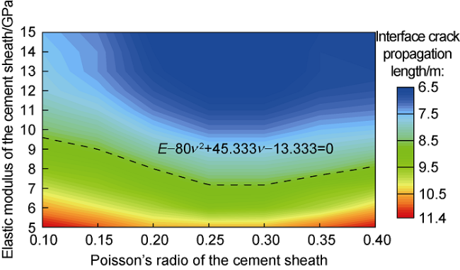
Fig. 10. Influence of elastic modulus and Poisson's ratio on the interface crack length. |
It is observed that when elastic modulus of the cement sheath remains constant, an increase in the Poisson's ratio has a nonlinear influence on the propagation length of the interface crack [9]; when the Poisson's ratio is constant, the greater elastic modulus of the cement sheath, the shorter the propagation length is. When elastic modulus and Poisson's ratio of the cement sheath satisfy the condition of $E-80{{\nu }^{2}}+45.333\nu -13.333\ge 0$ (the area above the dotted line in Fig. 10 ), the interface crack propagation length is less than 8.7 m, and it can be ensured that the interface crack will not be connected to the adjacent fracturing section.
4.3. Influence of elastic modulus and Poisson's ratio on the propagation direction of the zigzag crack
When the crack spreads along the interface, it also tends to spread to the cement sheath or formation on both sides of the interface [13]. Observing Eq. (16), it is found that the fracture angle of the crack is affected by the bi-material constant (ε) and interface crack stress field. Under the condition of constant formation and fracturing parameters, elastic modulus and Poisson's ratio of the cement sheath are the main factors affecting the interface crack stress field SIF and bi-material constant. When the bi-material constant is positive and the fracture propagation angle is negative, the zigzag crack will propagate to Material 2 (formation); when the bi-material constant is negative, the cement sheath and formation must be re-assumed. Moreover, if the fracture angle is negative, the crack will zigzag into the cement sheath.
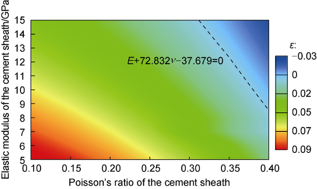
Fig. 11. Influence of elastic modulus and Poisson's ratio on the zigzag propagation direction of the crack. |
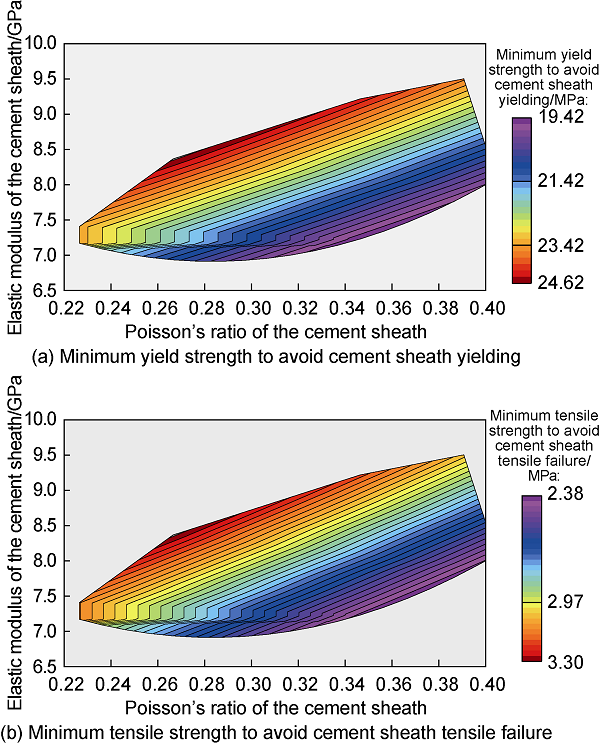
4.4. Influence of elastic Modulus and Poisson's Ratio on the strength requirements of the cement sheath
Keeping the fracturing condition unchanged, the three- dimensional stress of the cement sheath was calculated under different elastic moduli and Poisson's ratios, and the critical yield strength is analyzed to avoid the yield of the cement sheath based on Eq. (1). Based on the circumferential stress of the cement sheath, the critical tensile strength to avoid tensile failure is obtained. The results are shown in Fig. 12 .
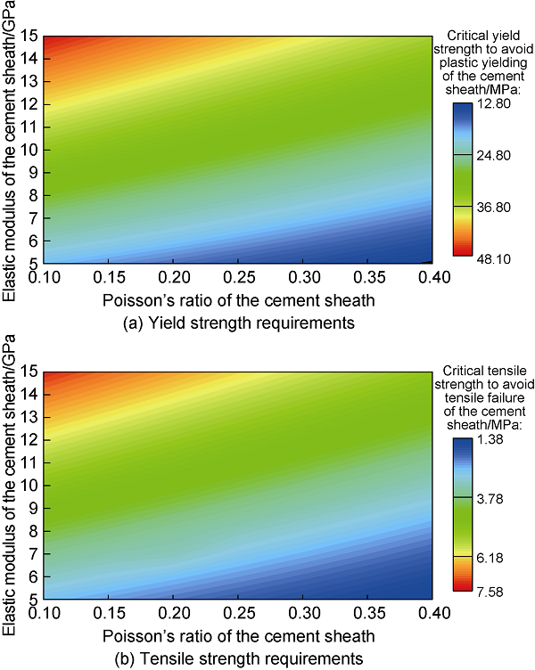
Fig. 12. Influence of elastic modulus and Poisson's ratio on the strength requirements of the cement sheath. |
It can be observed that if the cement sheath has a lower elastic modulus and higher Poisson's ratio, lower yield strength and tensile strength are required to avoid yield and tensile failure of the cement sheath during fracturing.
5. Requirements for properties of cement sheath to ensure wellbore sealing
For different failure modes, there are different optimization directions for the mechanical properties of the cement sheath. Only when the mechanical properties of the cement sheath consider the mechanical integrity and interface sealing integrity, an effective sealing of the wellbore can be ensured. By plotting the required range of mechanical properties to avoid cement sheath yielding, interface sealing failure, interface crack zigzagging into the cement sheath, the wellbore safe and risk areas caused by changes in elastic modulus and Poisson's ratio of the cement sheath can be obtained (Fig. 13 ).
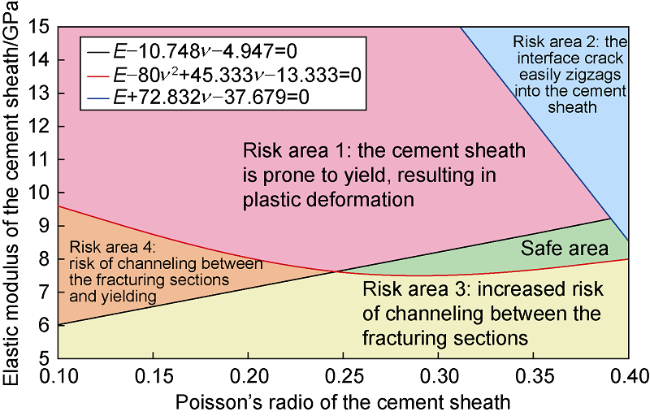
Fig. 13. Safe and risk areas based on the change in the elastic modulus and Poisson's ratio of the cement sheath. |
It can be observed that risk areas can be divided into four types: (1) The risk area where the cement sheath is prone to yield, resulting in plastic deformation; (2) The risk area where the interface crack easily zigzags into the cement sheath, leading to damage in the cement sheath; (3) The risk area where the interface crack propagates too long, resulting in an increased risk of mutual channeling between the fracturing sections; and (4) The risk area of cement sheath yielding and mutual channeling between the fracturing sections. There is only one safe area, which is the green range in Fig. 13 . When elastic modulus and Poisson's ratio of the cement sheath are within this area, the cement sheath integrity does not fail. Meanwhile, elastic modulus and Poisson's ratio in the safe area correspond to the strength in Fig. 12 , and the required range of the cement sheath strength to ensure wellbore sealing can be obtained, as shown in Fig. 14 .
Fig. 14. Requirement for the cement sheath yield and tensile strength. |
We consider the peak strengths in Fig. 14 as the requirements for the yield strength (24.62 MPa) and tensile strength (3.30 MPa) for the cement sheath. At this point, it can be considered that the strength, elastic modulus, and Poisson's ratio of the cement sheath can ensure the integrity of the cement sheath and wellbore sealing under fracturing conditions.
6. Conclusions
Based on the elastic-plastic model of the cement sheath and stress field model of the interface crack, considering various failure modes, such as the tensile failure and plastic yielding of the cement sheath, the interface crack propagation along the interface and interface crack zigzag propagation, an evaluation method for the wellbore sealing and a design method in regard to the mechanical properties of the cement sheath have been established. Model calculation verification with an example was performed to prove that the calculation accuracy is high.
Based on the design method with respect to the mechanical properties of the cement sheath, a quantitative design chart of elastic modulus and Poisson's ratio of the cement sheath has been constructed, the safe and risk areas of the wellbore have been clarified, and the yield and tensile strengths of the cement sheath have been quantified, which is convenient for field application.
Decreasing elastic modulus and increasing the yield strength and Poisson's ratio of the cement sheath can avoid the plastic deformation of the cement sheath; increasing the tensile strength of the cement sheath can prevent its tensile failure. Additionally, increasing elastic modulus and Poisson's ratio of the cement sheath can shorten the interface crack length. However, this increases the risk of the interface crack zigzagging into the cement sheath.
Nomenclature
a—interface crack length, m;
b—weight coefficient reflecting the influence of the intermediate principal stress, dimensionless;
${{B}_{\text{j}}}\left( {{\theta }_{\text{o}}} \right)$—a function of the fracture angle of the zigzag crack, dimensionless;
Ec—elastic modulus of the cement sheath, Pa;
E—elastic modulus, Pa;
i—imaginary unit;
K—integration constant, m2;
K1, K2—stress intensity factors of the open and shear modes of the interface crack, MPa•m1/2;
K1,σ, K2,σ—stress intensity factors of the open and shear modes of the interface crack affected by interface stress, MPa•m1/2;
K1,p, K2,p—stress intensity factors of the open and shear modes of the interface crack affected by fracturing load, MPa•m1/2;
$K_{1,2}^{*}$—stress intensity factor for the interface crack, MPa•m1/2;
KIC,ini—critical stress intensity factor for judging the interface crack propagation, MPa•m1/2;
$K_{,}^{*}$—stress intensity factor for the zigzag propagation of material on one side of the interface, MPa•m1/2;
KIJ,ini—critical stress intensity factor for judging the zigzag crack propagation, MPa•m1/2;
M, N—intermediate variables, dimensionless;
p1—casing-cement sheath contact pressure, Pa;
p2—cement sheath-formation contact pressure, Pa;
pi—internal casing pressure, Pa;
pin—thick-walled cylinder inner wall pressure, Pa;
po—formation pore pressure, Pa;
pout—thick-walled cylinder outer wall pressure, Pa;
pp—contact pressure of the cement sheath elastic-plastic interface, Pa;
r—radius at any points in casing-cement sheath-formation, m;
r1—radius of the outer wall of the casing (inner wall of the cement sheath), m;
r2—radius of the outer wall of the cement sheath (inner wall of the formation), m;
ri—radius of the inner wall of the casing, m;
ro—radius of the outer wall of the formation, m;
rp—radius of the elastic-plastic interface of the cement sheath, m;
R—radius at any points in the thick-walled cylinder, m;
Ri—inner radius of the thick-walled cylinder, m;
Ro—outer radius of the thick-walled cylinder, m;
u—displacement, m;
ucei—displacement of inner wall in the elastic zone of the cement sheath, m;
uceo—displacement of outer wall in the elastic zone of the cement sheath, m;
ucp—displacement of any position in the plastic zone of the cement sheath, m;
ucpi—displacement of inner wall in the plastic zone of the cement sheath, m;
ucpo—displacement of outer wall in the plastic zone of the cement sheath, m;
ufi—displacement of the formation inner wall, m;
uso—displacement of the outer wall of the casing, m;
X—axial coordinate of the wellbore, m;
Y—vertical coordinate of the wellbore, m;
α—the ratio of tensile strength to compressive strength, dimensionless;
ε—bi-material constant, dimensionless;
θ0—the fracture angle of the zigzag crack, (°);
ν—Poisson’s ratio, dimensionless;
ν1, ν2—Poisson’s ratio of materials 1 and 2, dimensionless;
νc—Poisson’s ratio of the cement sheath, dimensionless;
σ—stress, Pa;
σb—bonding strength, Pa;
σc—yield strength of the cement sheath, Pa;
σcf—stress at the cement sheath-formation interface, Pa;
σcf,i—initial stress at the cement sheath-formation interface, Pa;
σcf,p—interface stress increment due to the wellbore pressure, Pa;
σr—radial stress,
σx—fracturing fluid load parallel to the wellbore direction, Pa;
σx,p—the stress in the direction parallel to the interface caused by the fracturing load, Pa;
σy—stress perpendicular to the interface, Pa;
$\sigma _{\text{y}}^{+}$, $\sigma _{\text{y}}^{-}$—stresses in the direction of the formation and wellbore caused by the fracturing load, Pa;
σy,p—stress perpendicular to the interface caused by the fracturing load, Pa;
σz—axial stress, Pa;
σθ—circumferential stress, Pa;
μ1, μ2—shear moduli of materials 1 and 2, Pa;
τxy—stress parallel to the interface, Pa.