

Introduction
High-pressure water jet technology is widely used as an efficient rock-breaking method. It is used in oil drilling, coal mining, roadway excavation and other fields [1-2]. However, due to high rock-breaking threshold pressure and limited pumping pressure, it is difficult to achieve volume rock breaking, resulting in large rock breaking specific energy [3]. Swirling jet can create a three-dimensional velocity field by adding impeller guide elements inside the nozzle. In addition to tensile and water wedge effects [4] caused by vertical impact on the rock, tangential loads parallel to the rock surface are also formed [5]. Previous experiments showed that, on the same rock, the rock-breaking threshold pressure of swirling jet is only about 60% of that of straight jet [6]. Therefore, the rock breaking efficiency can be significantly improved [7]. In addition, the rock-breaking area of swirling jet is about ten times that of straight jet due to its spread characteristics [8]. At the same time, the back-flow from swirling jet radiates outwardly in a rotating mode, which reduces the interference to the jet column, and contributes to the improvement of rock-breaking efficiency.
The fundamental reason for the efficient rock-breaking ability of swirling jet is its unique swirling flow field structure. Many scholars have done a lot of researches on the flow field distribution of swirling jet. Bu et al. [9] and Ni et al. [10] measured the velocity distribution of swirling jet in submerged state with the five-hole probes. They found that the axial velocity profile presented an "M" shape distribution, while the tangential velocity profile presented an "N" shape distribution. Wang [11] found that the radial velocity distribution of swirling jet was in the shape of "M" under submerged conditions. The tangential velocity generated by the swirling jet increased the jet diffusion angle, but the axial symmetry characteristic of the tangential velocity was weakened under submergence conditions. Li [12] compared and analyzed the influence of different structural parameters on the swirling nozzle performance through numerical simulation on swirling-abrasive jet flow field by FLUENT software, based on fluid swirling flow and multi-phase flow mechanics theory. Wu et al. [13] analyzed the influence of nozzle structure parameters on swirling jet through numerical simulation, such as the outlet angle of impeller groove, impeller area and the convergence angle of mixing cavity. Previous studies mainly focused on the velocity distribution and the influence of nozzle structure on the flow field. However, they ignored many detailed characteristics of the flow field. Moreover, little literature has studied the development process of the flow field of swirling jet, such as the development characteristics of turbulence pulsation in the jet shear layer and the evolution process of large vortex structures. In order to deeply understand the flow characteristics of swirling jet and select appropriate engineering application scenarios, this paper intends to use numerical simulation methods to study the flow field evolution of swirling jet. The commonly used numerical simulation methods for studying jet flow field include Reynolds average Navier-Stokes (RANS) method and large eddy simulation (LES) method. RANS method is based on Reynolds averaged equation to study the time-averaging characteristics of flow field, which has the advantage of low computational complexity. However, it can only predict the average velocity field, average scalar field and average force of turbulence [14]. The vortex structures of different scales in the flow field cannot be captured precisely. LES method can effectively deal with unsteady complex flows, such as free jet flow and shear turbulence, by calculating all turbulent motions above a specific scale [15]. However, due to its high-resolution requirements for the wall boundary layer, the vast number of grids is restricted by computing resources [16]. The detached eddy simulation (DES) method, also known as the coupling LES/RANS algorithm, has the advantages of high precision of LES and low computational cost of RANS, so it is more suitable for solving the high Reynolds number turbulence problem. DES method uses a RANS turbulence model to analyze the flow field in the boundary layer and LES to calculate the turbulence region dominated by large vortices outside the boundary layer. Both the near-wall computational speed and the flow field accuracy far from wall surface are guaranteed simultaneously [17]. Several RANS turbulence models have been applied to the DES method, including Spalart-Allmaras model, Realizable k-ε model, Shear Stress Transport model (SST k-ω) and Transition SST model [18].
This paper uses an improved delayed detached eddy simulation (IDDES) method based on DES and an SST k-ω turbulence model to simulate the flow field of swirling jet at a high Reynolds number. The evolution processes of the vorticity, velocity and pressure fields of swirling jet are studied, the influence of nozzle pressure drop on large vortex structures and turbulent pulsation is explored, and the mechanism and flow field structure of swirling jet are revealed. The findings provide theoretical guidance for selecting suitable engineering application scenarios for swirling jet.
1. Numerical simulation model
The model is established based on the following assumptions: (1) ignore the effect of temperature change on fluid, (2) without considering the energy loss during jet impingement, and (3) the solid wall surface is smooth.
1.1. Mathematical model
1.1.1. Governing equation
The jet impact process under high-pressure is an unsteady viscous flow. When calculating the flow field, continuity equation and momentum equation should be satisfied first, and the governing equation is as follows:
$\frac{\partial {{\rho }_{f}}}{\partial t}+\frac{\partial \left( {{\rho }_{f}}{{v}_{i}} \right)}{\partial {{x}_{i}}}=0$
$\frac{\partial \left( {{\rho }_{f}}{{v}_{i}} \right)}{\partial t}+\frac{\partial \left( {{\rho }_{f}}{{v}_{i}}{{v}_{j}} \right)}{\partial {{x}_{j}}}=-\frac{\partial p}{\partial {{x}_{i}}}+\frac{\partial }{\partial {{x}_{i}}}\left( \mu \frac{\partial {{v}_{i}}}{\partial {{x}_{j}}} \right)+{{S}_{i}}$
1.1.2. Turbulence model
The research objective of this paper is the jet impact flow field at a high Reynolds number. We use an IDDES method based on DES and an SST k-ω turbulence model to calculate the flow field. The IDDES model can realize the adjustment between the LES analytical logarithm layer and the RANS simulated logarithm layer in boundary layer calculation, which solves the mismatch of the logarithm layers. IDDES provides a more flexible scale resolution and simulation method for flow fields at high Reynolds numbers [19]. The SST k-ω turbulence model is a two-equation eddy viscous turbulence model. The model takes into account the transport of turbulent shear stress. It can simulate turbulence at low Reynolds numbers without additional viscosity attenuation function and be applied to areas far away from the boundary layer [20]. Therefore, compared with other models, the SST k-ω model has higher accuracy and broader adaptability in flow scenarios such as inverse pressure gradient flow and airfoil transonic shock. In the SST k-ω turbulence model, the transport equations of turbulence kinetic energy (k) and specific dissipation rate (ω) are [21-22]:
$\frac{\partial \left( {{\rho }_{f}}k \right)}{\partial t}\text{+}\frac{\partial }{\partial {{x}_{i}}}\left( {{\rho }_{f}}k{{v}_{i}} \right)\text{=}\frac{\partial }{\partial {{x}_{j}}}\left( {{\Gamma }_{k}}\frac{\partial k}{\partial {{x}_{j}}} \right)+{{G}_{k}}-{{Y}_{k}}+{{S}_{k}}$
$\frac{\partial }{\partial t}\left( {{\rho }_{f}}\omega \right)\text{+}\frac{\partial }{\partial {{x}_{i}}}\left( {{\rho }_{f}}\omega {{v}_{i}} \right)\text{=}\frac{\partial }{\partial {{x}_{j}}}\left( {{\Gamma }_{\omega }}\frac{\partial \omega }{\partial {{x}_{j}}} \right)+$ ${{G}_{\omega }}-{{Y}_{\omega }}+{{D}_{\omega }}+{{S}_{\omega }}$
$\frac{\partial \left( {{\rho }_{f}}k \right)}{\partial t}+\nabla \left( {{\rho }_{f}}kv \right)=\nabla \left[ \left( \mu +{{\sigma }_{k}}{{\mu }_{t}} \right)\nabla k \right]+{{P}_{k}}-\frac{{{\rho }_{f}}\sqrt{{{k}^{3}}}}{{{L}_{IDDES}}}$
$\frac{\partial \left( {{\rho }_{f}}\omega \right)}{\partial t}+\nabla \left( {{\rho }_{f}}\omega v \right)=\nabla \left[ \left( \mu +{{\sigma }_{\omega }}{{\mu }_{t}} \right)\nabla \omega \right]+$ $2\left( 1-{{F}_{1}} \right){{\rho }_{f}}{{\sigma }_{\omega }}\frac{\nabla k\nabla \omega }{\omega }+\alpha \frac{{{\rho }_{f}}}{{{\mu }_{t}}}{{P}_{k}}-\beta {{\rho }_{f}}{{\omega }^{2}}$
where ${{P}_{k}}={{\mu }_{t}}\frac{\partial {{v}_{i}}}{\partial {{x}_{j}}}\left( \frac{\partial {{v}_{i}}}{\partial {{x}_{j}}}+\frac{\partial {{v}_{j}}}{\partial {{x}_{i}}} \right)$
${{\mu }_{t}}={{\rho }_{f}}\frac{0.31k}{\max \left( 0.31\omega,{{F}_{2}}S \right)}$
${{L}_{IDDES}}={{\tilde{f}}_{d}}{{L}_{RANS}}+(1-{{\tilde{f}}_{d}}){{L}_{LES}}$
${{L}_{RANS}}=\frac{\sqrt{k}}{{{C}_{\mu }}\omega }$
${{L}_{LES}}={{C}_{DES}}\Delta $
$\Delta =\min \left\{ \max \left\{ {{C}_{\omega }}{{d}_{w}}, \right. \right.{{C}_{\omega }}{{h}_{\max }},\left. \left. {{h}_{wn}} \right\},{{h}_{\max }} \right\}$
${{\tilde{f}}_{d}}=\max \left\{ 1-\left[ 1-\tanh {{\left( {{C}_{dt1}}{{r}_{dt}} \right)}^{{{C}_{dt2}}}} \right],{{f}_{b}} \right\}$
${{r}_{dt}}=\frac{{{\upsilon }_{t}}}{{{\kappa }^{2}}{{d}_{w}}^{2}\sqrt{0.5\left( {{S}^{2}}+{{\Omega }^{2}} \right)}}$
${{f}_{b}}=\min \left\{ 2\exp \left[ -9{{\left( 0.25-\frac{{{d}_{w}}}{{{h}_{\max }}} \right)}^{2}} \right],\ \text{1} \right\}$
1.2. Geometric model and meshing
The flow field model of the swirling jet is shown in Fig. 1 a. The coordinate origin is at the center of the impeller top. The flow field model includes the swirling nozzle flow field inside impeller and the external flow field. The flow field in the impeller is composed of three rotationally symmetric helical flow channels with a rotation angle of 360°. The nozzle diameter D is 5 mm, and the external flow field is set as a cuboid with a length of 70 mm, a width of 70 mm and a height of 80 mm. The high-pressure fluid flows into the nozzle inlet, then it is guided by the impeller and accelerated through contraction section and development section, and finally enters the external flow field in a spiral shape radially and flows out in radial direction after impacting the bottom plane. The model adopts pressure inlet and outlet boundary conditions. The wall surface of the rotating nozzle and bottom impact surface adopts standard no-slip wall boundary conditions.
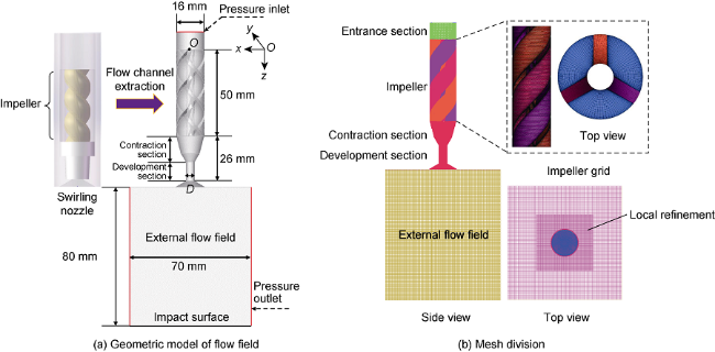
Fig. 1. Numerical simulation model of swirling jet flow field. |
The geometrical model of the swirling jet was imported into the pre-processing software ICEM CFD (The Integrated Computer Engineering and Manufacturing Code for Computational Fluid Dynamics). In order to improve the grid quality and enhance the calculation accuracy and convergence, structured mesh division is adopted (Fig. 1 b). Due to the complex structure of the flow channel in swirling nozzle, the jet model was divided into four sub-blocks (entrance section, contraction and development section, impeller section, and external flow field), for which specific topological structures were built, respectively. The grids of four sub-blocks are connected by Interface. The entrance section and contraction & development section are cylinder-like, which adopted the O-type mesh division technology to improve the quality of the grids at the circular boundary. The impeller section is composed of several curved streamlines. The mesh in this part is discretized by segmental cutting and rotational symmetry. The external flow field is a rectangle and it is the main development section of swirling jet. In order to improve the computational efficiency and accurately capture the complex turbulence characteristics of swirling jet, the mesh within the shear layer of the jet is refined. Since the turbulent distribution of the external flow field dominated by large eddy is calculated through LES, the cut-off scale of LES is mainly related to the local grid scale. Mesh size can be selected according to the size of the vortex structure required [24]. Considering the influence of calculation efficiency and flow field resolution, the mesh size of the external flow field and central refined mesh is finally selected as 0.6 mm and 0.3 mm, respectively. In addition, considering the influence of the boundary layer, the mesh of the swirling nozzle wall surface is refined. After the refinement, the overall flow field mesh number is 730×104, and the mesh quality remains above 0.6, which could meet the requirement of high-speed flow field simulation [25]. In order to further improve the accuracy of DES simulation, the solving speed of the model should be higher than the propagating speed of the actual physical disturbance to obtain the vortex structure with small scale of the jet flow. In this study, the simulation time step Δt is set as 1×10⁻⁶ s, and the corresponding Courant number (CFL) is less than 0.6, which ensure high simulation accuracy [16]. The jet fluid in the model is liquid water, with a viscosity of 1.003×10⁻³ Pa·s and a density of 998.2 kg/m3. The model inlet and outlet pressures (outlet pressure is the ambient confining pressure) are 30 MPa and 20 MPa, respectively. The iterative step in unit time is 40.
1.3. Numerical model validation
The experimental data of Tummers et al. [26] were used to verify the accuracy of the numerical model. Tummer's experiment studied the turbulent impingement flow field at Reynolds number of 23 000, and measured the velocity distribution of the impingement flow field. The result has been widely accepted by scholars for its high reliability[27-28]. Tummers et al. used a round pipe impingement jet in their experiment, which is similar to the flow field of the impingement jet in this paper to some degree. We used the IDDES method based on an SST k-ω model to simulate the impact flow field under experimental conditions to verify the accuracy of the turbulence model under the impact jet flow field condition. Fig. 2 a-2b shows the velocity distribution at the central axis and the section 7 mm away from the nozzle outlet. The dimensionless velocity term v/va was used to characterize the velocity in Fig. 2 , where v is the fluid velocity at a given point in the flow field, and va is the average velocity at the nozzle outlet. The numerical results agree with the experimental data, which has verified the accuracy of the turbulence model used in this paper in calculating the flow field of the impingement jet.
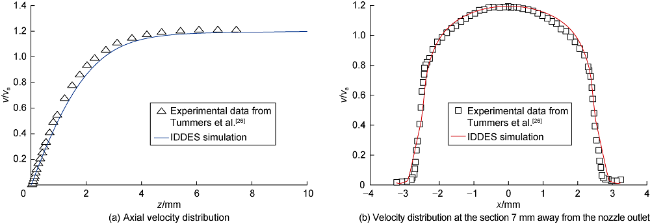
Fig. 2. Simulation result and experimental data. |
2. Simulation results and discussion
2.1. Vorticity distribution
2.1.1. Evolution process of swirling jet vortex
The time-series evolution process of the vortex structure of swirling jet is shown in Fig. 3 . The turbulence evolution with disordered motion can be described by the deformation, stretching and breaking of the three-dimensional vortex elements [15]. In this paper, we used Q-criterion isosurface [29] to identify and characterize the quasi-ordered structure of vortices. The vortex structure was calibrated with axial velocity. Based on the vortex evolution and previous research [30], the evolution of swirling jet vortex can be divided into three stages: Kelvin-Helmholtz (K-H) instability stage, transition stage, and swirling instability stage.
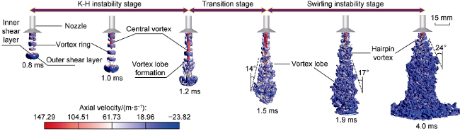
Fig. 3. Evolution of the vortex structure of swirling jet. |
When swirling jet initially entered the external flow field, it was mainly controlled by K-H instability in the shear layer. Internal spiral convergence occurred in the fluid, forming a vortex ring sequence with the size close to the nozzle outlet perpendicular to the direction of the jet. The vortex ring consists of inner and outer shear layers. The velocity of the inner shear layer is higher and consistent with the direction of the jet. In comparison, the velocity of the outer shear layer is lower and opposite to the direction of the jet. On the whole, the vortex structure is relatively stable in K-H instability stage.
As the jet advanced, swirling instability increased, which made the jet shear layer instable. Moreover, the circumferential quasi-order of the vortex ring decreased, resulting in tensile failure. At the edge of the vortex ring, vortex curl and vortex pairing occurred, forming vortex lobes. Meanwhile, the central vortex structure was generated inside the vortex ring and extended downward along the axis. The existence of this structure has also been observed in the flow field of the swirl burner [30]. At about 1.2 ms, "vortex breakdown" occurred [31], which means the backflow occurred at the jet end. It is generally believed that the backflow zone is related to the centrifugal force caused by the rotation effect [32]. According to the continuity equation and Bernoulli equation, the radial pressure gradient will be generated near the jet axis due to circumferential velocity. Near the nozzle outlet, the circumferential velocity is high and the rotation effect is strong, resulting in lower pressure. Along the downstream of the jet flow, circumferential velocity attenuated, the rotation effect weakened, and the pressure near the axis gradually recovered. Therefore, the "inverse pressure gradient" phenomenon of low upstream pressure and high downstream pressure is formed at the jet axis [31]. When the inverse pressure gradient reached a certain degree, fluid backflow occurred, promoting the mixing the jet flow and ambient fluid and increasing the jet diffusion range. At 1.9 ms, the jet impinged on the bottom plane. The fragmentation degree of vortex lobes increased with further development of the jet structure, and radial flow appeared on the impact surface.
At about 4.0 ms, the jet structure has been fully developed, and the rotational instability became dominant. The development of circumferential velocity increased the momentum exchange between internal and external fluids, and the jet expanded further along the radial direction. Hairpin and streamwise vortex structures were formed near the shear layer [31]. At the same time, the large-scale vortex structures downstream interacted, merged, and continuously cracked to form new small-scale vortex structures. In the stage with fully developed swirling jet, radial expansion caused by the rotation effect is beneficial to increasing jet diffusion angle and impact area.
In the stable flow field, we used streamline density to characterize the vortex structure in external flow field and the velocity vector to represent the direction of fluid motion (Fig. 4 ). The streamlines could be divided into the fluid from the nozzle and the ambient fluid. Most fluid from the nozzle directly impacted the bottom plane along the jet axis, and then left the flow field in the radial direction, while the fluid from the external flow field was the primary vortex source in the shear layer. It can be seen from the distribution of the vortex structure in the shear layer that small vortices formed near the nozzle outlet and then gradually developed and expanded downwards. At 2.9 ms, there were mainly three large vortex structures A, B and C in the flow field. And Vortex A gradually differentiated into A' and A". From the change of streamline density, it can be found that the change of vortex strength decreased first and then increased. First, the large vortex structure in the shear layer attracted the low-speed fluid around the jet into the jet. Then the vortex intensity and the streamline density decreased gradually. However, when the fluid reached the bottom impact surface, the streamline density and vortex strength increased again influenced by radial flow and fluid accumulation at the stagnation point.
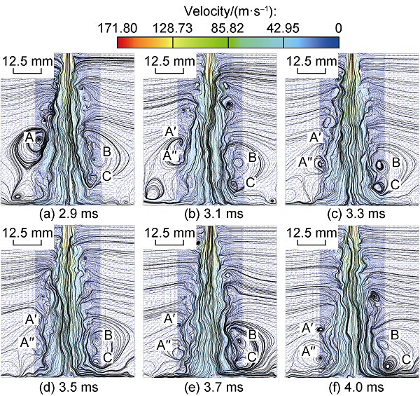
Fig. 4. Vortex distribution of the external flow field. |
2.1.2. Effect of pressure drop on vortex structure distribution
According to Fig. 5 a, the distribution of vortex in the external flow field remains consistent on the whole during evolution process, and increasing the jet pressure drop has no significant effect on the distribution of the vortex structures. However, more small vortex structures develop in the shear layer near the nozzle outlet as pressure drop increases. It is because the jet velocity increases significantly with pressure drop. And based on Bernoulli's principle, static pressure significantly reduces, and further increases the pressure difference between the fluid in the shear layer and ambient fluid, which enhances the jet entrainment ability to low-speed fluid.

Fig. 5. Vortex structure cloud maps (a) and helicitydistribution cloud maps (b) of the external flow field under different pressure drops. |
2.2. Velocity distribution
2.2.1. Flow field evolution and velocity distribution
From Fig. 6 a, when the jet initially entered the flow field, the structure of the jet was not fully developed, and the shape of the jet was spindly. At about 2.0 ms, the jet impacted on the bottom plane, resulting in a radial flow. Meanwhile, the jet diffusion angle gradually increased under the jet entrainment effect of the shear layer, and the shape of the swirling jet was initially formed. With the evolution of the flow field, the jet was constantly mixing the low-velocity fluid from surroundings. The flow filed structure was fully developed at 3.0-4.0 ms, and the jet core velocity and the diffusion angle became stable. Outside the jet core region, jet flow and ambient fluid were sufficiently disturbed, accompanied by decreased total pressure and velocity and enhanced turbulence pulsation. From Fig. 6 b, compared with the steady flow field at 4.0 ms, the velocity at 1.5 ms is higher and the fluctuation range is smaller near the nozzle outlet. This is because the swirling jet structure has not been formed at this stage, and the turbulence pulsation was weak, so the velocity dropped more slowly. Therefore, it is further confirmed that the main reason for the velocity attenuation is the dissipation of turbulence pulsation caused by swirling flow.
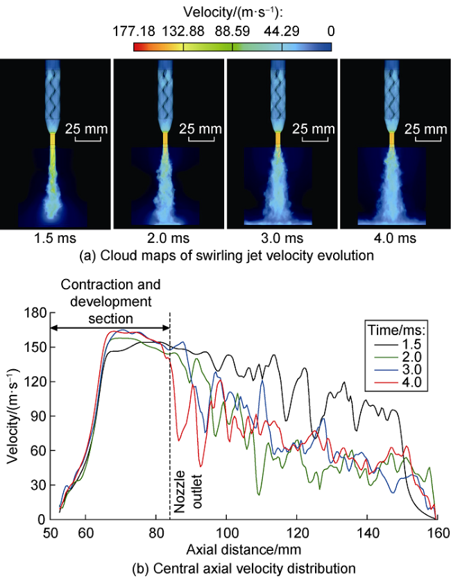
Fig. 6. Velocity cloud maps (a) and axial velocity distribution (b) of swirling jet. |
At pressure drop of 10 MPa and 4.0 ms, cloud maps of different swirling jet velocity components and velocity distribution curves under corresponding dimensionless jet distance (where the dimensionless jet distance is the ratio of the axial distance between nozzle outlet and impact surface to the nozzle diameter) are shown in Fig. 7 . The velocity of the swirling jet is decomposed into three directions (x, y and z). vx and vy determine the rotating effect of the jet, and vz determines the transport capacity of the swirling jet. The radial velocity components vx and vy curve present rotational symmetry distribution (Fig. 7 a), and in an "N" shape near the nozzle outlet (Fig. 7 b). As the jet distance increases, the jet range increases gradually due to the entrainment of low-speed fluid into shear layer, the symmetric form weakens, and the velocity attenuates rapidly. The velocity distribution curve of vz is in a M shape near the nozzle outlet. With the increase of jet distance, the "M" distribution disappears gradually and the velocity decreases rapidly, which is consistent with previous experimental observation results [9]. Compared with straight jet, swirling jet decreases the potential core length. It dissipates faster, but its higher circumferential velocity increases the radial expansion rate and turbulence pulsation intensity. The rotational effect could significantly enhance turbulence pulsation near the nozzle outlet, especially the radial turbulence pulsation. Downstream, the turbulent dissipation effect causes the rapid attenuation of turbulence pulsation, making the symmetric form of jet flow weak, and the velocity decreases rapidly.
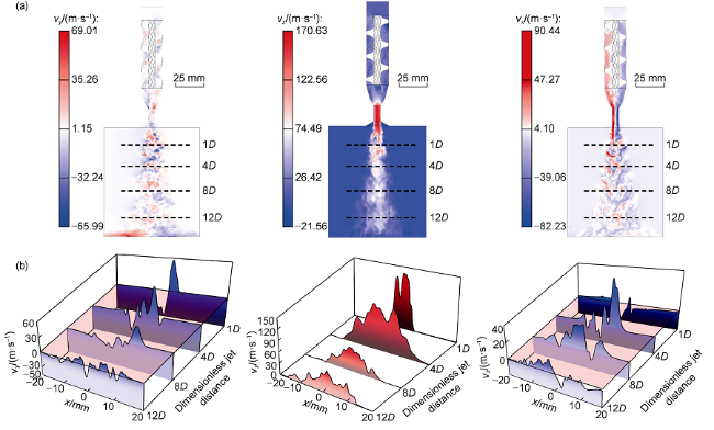
Fig. 7. Cloud maps of different velocity components (a) and velocity distribution curves at different jet distances (b). |
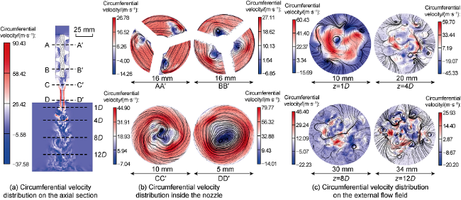
Fig. 8. Circumferential velocity cloud maps of swirling jet. |
By analyzing the variation of circumferential velocity, it is found that the swirling intensity depends on the structural characteristics of the contraction and development section. Therefore, increasing the length of the contraction and development section in the nozzle structure will benefit from higher circumferential and axial velocities, which increases the swirl intensity and transport capacity simultaneously, and finally increasing the effective jet distance in the external flow field and weakening the influence of turbulent dissipation.
2.2.2. Influence of pressure drop on jet velocity distribution
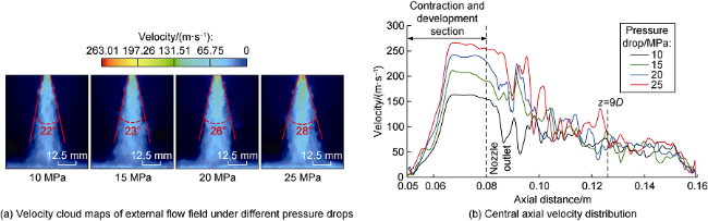
Fig. 9. Velocity cloud maps and axial velocity distribution curves of swirling jet under different pressure drops. |
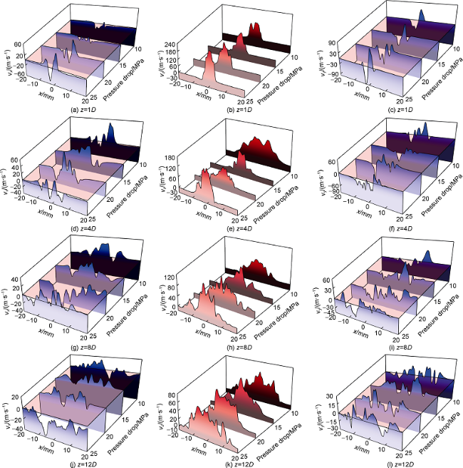
Fig. 10. Distribution curves of different velocity components of swirling jet. |
2.3. Pressure distribution
2.3.1. Pressure distribution and pressure evolution of external flow field
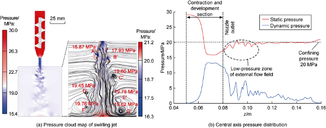
Fig. 11. Pressure cloud map of swirling jet (a) and axial pressure distribution (b). A°-G° represent vortices; the value means the pressure in the center of the vortex. |
2.3.2. Effect of pressure drop on pressure field distribution
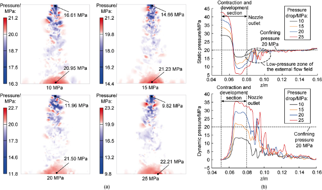
Fig. 12. Pressure cloud maps (a) and axial pressure curves (b) of swirling jet under different pressure drops. |
3. Conclusions
The development of vortex structure of swirling jet can be divided into three stages: Kelvin-Helmholtz (K-H) instability stage, transition stage, and swirling instability stage. Developed vortex structures in the shear layer promotes the momentum exchange between jet and ambient fluid. This process accelerates the jet to mix with ambient fluid, and expands jet diffusion area, but it also causes rapid attenuation of jet strength. The rotation effect can significantly enhance turbulence pulsation near the nozzle, especially radial pulsation, and making the velocity curve symmetric. At downstream, the main reason for velocity attenuation is the dissipation of turbulence pulsation caused by the rotation effect. The pressure distribution of swirling jet is closely related to velocity. Due to the rotation effect, the pressure at the nozzle outlet is much lower than the surrounding confining pressure. The vortex structure developed at the edge of the low-pressure region in external flow field, which is beneficial for promoting the mixing of jet with abrasive particles. This is of great significance in improving the impact strength and range of abrasive jet.
Around the nozzle outlet, pressure drop significantly influences the vortex structure, velocity field and pressure field of swirling jet. The swirl intensity and radial turbulence pulsation can be significantly increased by increasing pressure drop, thus increasing the diffusion angle and impact range. However, the influence of pressure drop dissipates when the jet distance is larger than 9D due to strong turbulent dissipation, it’s not possible to increase the effective impact distance by further pressure drop anymore. In conclusion, swirling jet is more suitable for radial horizontal drilling with large hole size, horizontal well cavity completion and coal mine roadway drilling, etc.
Nomenclature
Cdt1, Cdt2, Cμ, Cω—empirical constant, dimensionless;
CDES—calibration factor, dimensionless;
dw—distance from grid node to the nearest wall, m;
D—nozzle diameter, m;
Dω—diffusion term, kg/(m3·s2);
fb—empirical mixing function, dimensionless;
${{\tilde{f}}_{d}}$—screen function, dimensionless;
F1, F2—SST model mixing function, dimensionless;
Gk—generation term of turbulence kinetic energy k, kg/(m·s3);
Gω—generation term of specific dissipation rate ω, kg/(m3·s2);
hmax—maximum side length of a grid cell, m;
hwn—unit grid along the normal direction of the wall, m;
i, j—directions of the coordinate system, set as 1, 2, 3;
k—turbulent kinetic energy, m2/s2;
LIDDES—IDDES characteristic length, m;
LLES—LES characteristic length, m;
LRANS—RANS characteristic length, m;
p—fluid pressure, Pa;
Pk—generation term of turbulent kinetic energy, kg/(m·s3);
rdt—retardation factor, dimensionless;
S—rate of strain tensor, s-1;
Si—source term of momentum conservation equation, kg/(m2·s2);
Sk—custom source term of turbulent kinetic energy, kg/(m·s3);
Sω—custom source term of specific dissipation rate, kg/(m3·s2);
t—time, s;
v—fluid velocity at the given point in flow field, m/s;
va—average velocity at nozzle outlet, m/s;
v—velocity vector, m/s;
x, y, z—coordinates in space, m;
Yk—dissipation term of turbulent kinetic energy k, kg/(m·s3);
Yω—dissipation term of specific dissipation rate, kg/(m3·s2);
α, β—inhibitory factor of turbulence viscosity, dimensionless;
ε—dissipation rate, dimensionless;
Δ—cut-off length, m;
κ—Von Karmans constant, dimensionless;
μ—fluid dynamic viscosity, Pa·s;
μt—turbulent viscosity coefficient, Pa·s;
ρf—fluid density, kg/m3;
σk—the turbulent Prandtl number for k, dimensionless;
σω—the turbulent Prandtl number for ω, dimensionless;
Γk—effective diffusivity term of turbulent kinetic energy, kg/(m·s);
Γω—effective diffusivity term of specific dissipation rate, kg/(m·s);
υt—kinematic viscosity coefficient, m2/s;
ω—specific dissipation rate, s-1;
Ω—vorticity tensor, s-1;
$\nabla$—Hamiltonian operator.