

Introduction
With the development of unconventional oil and gas reservoirs, multi-well pad fracturing operation has become popular and promoted resource sharing and reuse, and saving cost while increasing production efficiency [1-2]. The concept of hydraulic fracturing stimulation evolved from single fractures to volume fracturing and finally to fracture-controlled stimulation. The primary purpose is to increase reservoir contact by fracturing techniques such as short well spacing, dense perforation and long horizontal section [3⇓-5]. The investigation to fracture propagation and proppant transport on a multi-well pad is of great significance for well placement and fracturing design, no matter in terms of technical or fracturing theories.
To satisfy the optimization of multi-well fracturing stimulation, inter-fracture stress interference was analyzed by studying the analytical solution of ideal fractures by various fracturing methods, such as alternate fracturing, zipper fracturing, simultaneous fracturing, and modified zipper fracturing [6⇓-8]. With the development of numerical simulation technology, scholars made great efforts to establish multi-well fracture propagation models based on coupled solid-fluid equations. Wu et al. [9] established a fracturing model between two horizontal wells to analyze inter-well interference and proposed that fractures induced in two wells tended to attract each other, which could lead to fracture coalesce and fracture hits. Sesetty et al. confirmed that the closure width of fractures had a significant influence on stress field and post-fracturing fracture propagation [10-11]. Although a high horizontal stress difference can effectively mitigate the influence of inter-well stress interference on fracture deflection, there are asymmetrical propagation of fracture wings and inadequate stimulated reservoir volume between wells [12⇓-14]. Qiu et al. found that there were optimum well spacing and cluster spacing in multi-well fracturing treatment, and zipper fracturing is more effective than sequential fracturing for reservoirs with natural fractures [15-16]. Furthermore, stimulation effectiveness is not only affected by fracture propagation and shapes, but also closely related to proppant distribution in fractures[17]. Experimental simulation to proppant transport and placement in hydraulic fractures is mainly based on large-scale slot flow devices, which enables visual observation of proppant movement [18-19]. Numerical simulation to proppant transport mainly follows the Euler-Lagrange framework (E-L) and the Euler-Euler framework (E-E)[20-21]. According to the E-L framework, the most common computational fluid dynamics-discrete element method (CFD-DEM) can be established to calculate accurate results in proppant simulation, but the computational efficiency is too low to be suitable for field-scale application. The E-E method is less computational and cost-effective because it characterizes proppant distribution by volume fraction or two-phase flow, and it can be coupled with fracture propagation models more efficiently. Dontsov et al. [22] coupled the E-E proppant transport model with the KGD (Khristianovich-Geersma-Daneshy) model and a pseudo-3D model to investigate proppant transport in a single fracture while it propagates and proposed that proppant bridges would slow down the flow of slurry, thus affecting fracture propagation. Wang et al. [23] established a coupled model of the PKN (Perkin-Kern- Nordgren) model and the E-E proppant transport model, and evaluated the influence of proppant distribution on residual fracture width and conductivity after fracture closure. In a word, prior studies on simulating proppant transport are based on a few hydraulic fractures, which could not account for stress interference between closely- spaced fractures during multi-well pad fracturing treatments.
It is difficult to accurately evaluate the effective volume of stimulated reservoir due to insufficient consideration of fracture propagation and proppant transport in multi-well pad fracturing treatment. In this work, a coupled model of 3D fracture propagation and proppant transport in multi-well fracturing treatment was established based on the discontinuous displacement method. Then, multi-fracture propagation geometry and proppant distribution in fractures were studied by using actual multi-well pad parameters, to promote the optimization and design for multi-well fracturing treatment.
1. Governing equations
1.1. Elasticity deformation
It is assumed that there are several planar fractures propagating in the direction of the maximum horizontal principal stress in an infinite and homogeneous reservoir. The three-dimensional discontinuity method is used to solve rock deformation. All fracture surfaces are discretized into rectangular grids, and the variables such as displacement and pressure are located at the center of the grid (Fig. 1 ).
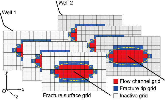
Fig. 1. 3D fracture surface grids. |
Considering that the tangential displacement of fracture is zero, and the normal displacement is equal to the fracture width w. The normal stress in a local coordinate system induced by a fracture grid at any point in the reservoir can be expressed as [24]:
${{\sigma }_{33}}=\frac{G}{4\pi (1-v)}w[{{I}_{33}}-{{x}_{3}}{{I}_{333}}]$
Since the model proposed in this paper is 3D planar fractures that ignore fracture deflection, the stress induced in a grid can be calculated only through one coordinate transformation, and then the matrix equations of stress and displacement under the global coordinate system can be established through stress superposition principle:
$p-{{\sigma }_{\text{h}}}=Aw$
For multi-well and multi-stage fracturing operation on a well pad, it is assumed that the fractures induced in previous stages are supported by fluid, and induce stress shadow that affects fracture propagation in next stages.
1.2. Flow of proppant-carrying fluid
The flow of the proppant- carrying fluid in fractures is similar to the flow in thin plates, and it is incompressible Newtonian fluid. The mass conservation equation is [25]:
$\frac{\partial w\left( x,y,t \right)}{\partial t}+\nabla {{q}_{\text{s}}}\left( x,y,t \right)+{{v}_{\text{L}}}\left( x,y,t \right)=Q\left( t \right)\delta \left( x,y \right)$
Considering that the fluid flowing in fractures satisfies laminar flow, the momentum equation is described by the Poiseuille's law [26]:
${{q}_{\text{s}}}\left( x,y,t \right)=-\frac{{{w}^{3}}\left( x,y,t \right)}{12\mu }\nabla p\left( x,y,t \right){{\hat{Q}}_{\text{s}}}\left( \bar{\phi },\frac{w}{a} \right)$
where ${{\hat{Q}}_{\text{s}}}$is a dimensionless function representing the effect of proppants on fluid flow. It can capture the transform of fluid flow from the Poiseuille’s flow to the Darcy’s flow with the increase of normalized proppant concentration.
1.3. Proppant transport
According to the Euler-Euler framework, both proppant particles and fracturing fluid are treated as continuums. Considering that proppants have uniform particle sizes, the proppant transport equation is established based on the empirical constitutive model of fluid flow, which integrates the transform from the Poiseuille’s flow to the Darcy’s flow, proppant bridging and gravity settlement comprehensively [22]. In order to simulate proppant migration in propagating fractures, the proppant transport model and the fracture propagation model are sequentially coupled. Specifically, the proppant concentration distribution is calculated after the fracture width and pressure field are obtained from the coupled solid-fluid equation. The mass conservation equation of proppant can be expressed as:
$\frac{\partial w\left( x,y,t \right)\bar{\phi }}{\partial t}+\nabla {{q}_{\text{p}}}\left( x,y,t \right)={{\phi }_{0}}Q\left( t \right)\delta \left( x,y \right)$
The proppant flux is composed of an advective term and a gravitational settlement term:
${{q}_{\text{p}}}=B\left( \frac{w}{a} \right)\left[ {{{\hat{G}}}_{\text{p}}}\left( \bar{\phi },\frac{w}{a} \right){{q}_{\text{s}}}-\frac{{{a}^{2}}w}{12\mu }\Delta \rho g{{{\hat{G}}}_{\text{p}}}\left( \bar{\phi },\frac{w}{a} \right) \right]$
where${{\hat{Q}}_{\text{p}}}$ and ${{\hat{G}}_{\text{p}}}$ are dimensionless functions obtained based on the empirical constitutive model of fluid flow, and describe the proppant flow caused by fluid flow and gravity settlement, respectively.
1.4. Fracture propagation criterion
The process of fracture propagation involves the coupling of multiple physical fields such as rock deformation, fluid flow and fracture propagation, which results in complex and multi-scale behaviors at the fracture tips. The solution to linear elastic fracture mechanics takes into account the fracture propagation behavior dominated by toughness propagation and is only applicable to the fracture tip within a very small range under common engineering parameters. Therefore, accurate simulation requires extremely fine fracture elements [27-28]. In our model, the approximate expression of multi-scale-tip asymptotic solution is used as the fracture propagation criterion. This solution takes the fracture propagation dominated by toughness, viscosity, and leak-off into consideration, enlarges the application of the asymptotic solution, and can capture the multi-scale behaviors at fracture tips more accurately and efficiently. The critical fracture width satisfying fracture propagation is expressed as [29]:
${{w}_{\text{c}}}={{\left[ \frac{512{{K}_{\text{IC}}}^{3}}{{{{{E}'}}^{3}}}{{\left( \frac{r}{2\pi } \right)}^{\frac{3}{2}}}+{{3}^{\frac{5}{2}}}\frac{24u{{v}_{\text{tip}}}{{r}^{2}}}{{{E}'}} \right]}^{\frac{1}{3}}}$
1.5. Wellbore fluid flow and fluid distribution
Wellbore fluid flow equations are established according to the Kirchhoff's law to calculate the fluid distribution in fractures. Without considering wellbore storage effect, the fluid flow rate in the fractures induced in each stage should satisfy fluid volume conservation and pressure balance [30]:
$\left\{ \begin{align} & Q=\sum\limits_{i=1}^{N}{{{Q}_{i}}} \\ & {{p}_{\text{w}}}={{p}_{\text{f}}}+{{p}_{\text{p}}}\left( {{Q}_{i}} \right)+{{p}_{\text{c}}}\left( {{Q}_{i}} \right) \\ \end{align} \right.$
The equations of perforation friction and wellbore friction are as follows [31]:
${{p}_{\text{p}}}=\frac{8\rho {{Q}_{i}}^{2}}{{{\pi }^{2}}D_{\text{p}}^{4}N_{\text{p}}^{2}C_{\text{d}}^{2}}\ \ \ \ \ \ \text{ }{{p}_{\text{c}}}=\frac{128\mu }{\pi D_{\text{w}}^{4}}\sum\limits_{i=1}^{N}{{{{{Q}'}}_{i}}}{{L}_{\text{c}}}$
Considering that perforations may be gradually worn by high-rate proppant-carrying fluid, a model is built to consider the change of perforation diameters and the coefficient of fluid flow rate [32].
1.6. Numerical solution algorithm
In the multi-well pad fracturing numerical model, the three-dimensional discontinuous displacement method is used to solve the elasticity deformation, the finite volume method to solve the mass conservation equation of fluid flow, the RKL (Runge-Kutta-Legendre) super-time-stepping explicit method to solve the coupled solid-fluid equation [33-34], the weighted essential non-oscillating method to differentially discrete the space term of the proppant transport equation, and the third-order Runge-Kutta method to calculate the time term of the proppant transport equation [35]. The specific procedures are as follows: (1) Input basic parameters and grid fracture surfaces; (2) use the Newton-Raphson method to calculate the fluid flow rate in the fractures induced in each stage at a given time step; (3) calculate fracture width by fluid mass conservation equation and obtain the corresponding fluid pressure by elasticity deformation equation; (4) recalculate the fluid flow rate in the fractures induced in each stage according to the new fluid pressure until numerical convergence; (5) subdivide the time step and calculate the proppant concentration distribution on the proppant transport model; (6) use the multi-scale-tip asymptotic solution to calculate the critical tip width and determine whether fracture propagation occurs; (7) repeat steps 2-6 until the end of pumping treatment.
2. Numerical model verification and basic parameter
For the three-dimensional planar fracture propagation model, the accuracy can be verified by using the Penny-fracture analytical solution. The fracture surface grid is 2 m by 2 m. The basic parameters of the model are selected as follows: the injection rate is 5 m3/min; the fluid viscosity is 5 mPa·s; the Young's modulus is 30 GPa; the pumping time is 20 min; and the fracture toughness is 0.2 MPa·m0.5. In this case, the fracture propagation is dominated by viscous propagation. The fracture inlet width and fracture radius can be expressed by Eq. (9) [36].
$\left\{ \begin{align} & w\left( 0,t \right)=1.190\ 1{{\left[ \frac{{{\left( 12\mu \right)}^{2}}{{\left( 1-v \right)}^{2}}{{Q}^{3}}t}{{{E}^{2}}} \right]}^{1/9}} \\ & R\left( t \right)=0.694\ 4{{\left[ \frac{{{Q}^{3}}E{{t}^{4}}}{12\mu {{\left( 1-v \right)}^{2}}} \right]}^{1/9}} \\ \end{align} \right.$
Within the first 20 min, the numerical fracture width and radius are in good agreement with the analytical solutions, indicating that the numerical model is accurate and reliable (Fig. 2 ).
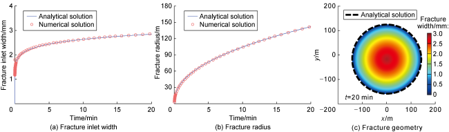
Fig. 2. Results of the numerical model proposed in the paper and analytical solutions. |
The shale oil reservoir of the Lucaogou Formation in the Jimsar Sag of the Junggar Basin, NW China is typical continental thin interbedded shale with deep burial and strong petrophysical heterogeneity. To achieve adequate stimulation and efficient development of the reservoir, multi-well pad fracturing stimulation has been applied in this sag. This paper uses the actual geological and engineering parameters of multi-well pad A in the Jimsar Sag (Table 1 ) as basic data to conduct numerical simulation to fracture propagation and proppant transport through zipper fracturing operation.
Table 1. Basic parameters of multi-well pad A |
| Parameter | Value | Parameter | Value |
|---|---|---|---|
| Yong’s modulus | 28 GPa | Cluster spacing | 8 m |
| Poisson’s ratio | 0.2 | Number of perfora- tions per cluster | 6 |
| Fracture toughness | 1 MPa·m0.5 | Perforation diameter | 12 mm |
| Reservoir thickness | 20 m | Discharge coefficient | 0.65 |
| Minimum horizontal principal stress | 60 MPa | Injection rate | 14 m3/min |
| Interbed stress difference | 5 MPa | Fluid viscosity | 10 mPa·s |
| Well spacing | 200 m | Fluid density | 1 000 kg/m3 |
| Wellbore diameter | 0.10 m | Proppant density | 2 500 kg/m3 |
| Stage interval | 48 m | Normalized proppant concentration | 0.1-0.25 |
| Number of clusters per stage | 6 | Average proppant size | 0.38 mm |
Note that the normalized proppant concentration is the ratio of proppant volumetric concentration to the maximum allowable volumetric concentration |
To fully consider the influence of inter-well and inter- stage stress interference on multi-fracture propagation and proppant transport during zipper fracturing stimulation on a well pad, simulation to multi-stage and multi- cluster fracturing operation was carried out on two adjacent horizontal wells, and the staggered distance of fractures between the two wells is equal to the half of the cluster spacing. During the hydraulic fracturing treatment, one well was fractured while the other well was plugged and perforated. In other words, the two wells were fractured alternately, by following the sequence “Stage 1-1→Stage 2-1→Stage 1-2→Stage 2-2” (Fig. 3 ).
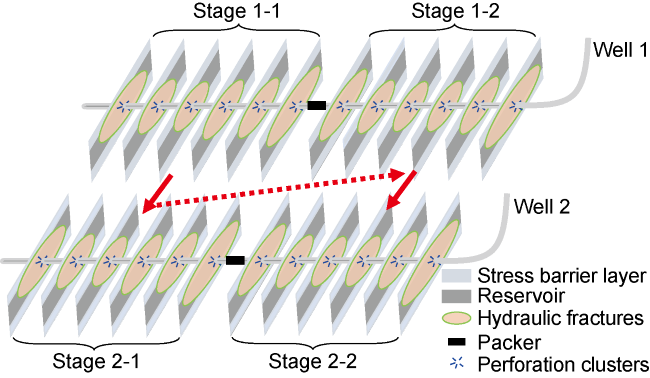
Fig. 3. Schematic of zipper fracturing operation in two wells (the red arrows indicate fracturing sequence). |
3. Fracture propagation geometry and proppant distribution
3.1. Geometry of multi-fracture propagation
The dynamic changes of the intensity and range of the induced stress field during zipper fracturing operation on a multi-well pad leads to the difference in the geometry of multi-fracture propagation and proppant concentration distribution in different stages. For the convenience of description and comparative analysis, the fractures are divided into positive and negative wings according to the propagation direction (the y axis). The fractures propagating from the wellbore and in the positive direction of the y axis are called positive fracture wings, and those in the negative direction of the y axis are called negative fracture wings. In addition, the clusters in any stages are numbered clusters 1-6 from toe to heel. During stage 1-1 fracturing, the propagation of the fractures presented a common non-uniform geometry under the influence of only in-stage stress interference. In addition to smaller length and width, the fractures related to the inner clusters tended to propagate in the direction of fracture height to avoid stress interference. This is the same as petal-like fracture morphology, which satisfies the minimum energy principle [37]. However, the fracture width was limited by the barrier layer with high compressive stress (Fig. 4 ).
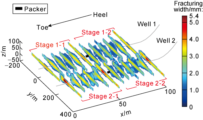
Fig. 4. Fracture propagation in multi-well zipper fracturing. |
Stage 2-1 started immediately after Stage 1-1. Under the influence of inter-well stress interference, the fractures propagated in an obviously asymmetric geometry. The fractures mainly tended to propagate in the direction of positive wings, and the vertical propagation was more significant in order to avoid the influence of stress interference. The microseismic monitoring results also showed that there was asymmetric fracture propagation caused by the well completion sequence in field [38], which not only intensified the uneven propagation of fractures but also reduced the reservoir volume stimulated on the well pad. The geometry of the fractures induced in Stages 1-2 is similar to that in Stage 1-1, and there are no obviously asymmetric fractures due to the smaller inter-well stress interference. However, the length and width of the fracture induced at the toe cluster in Stage 1-2 decreased significantly after being interfered by inter-stage stress interference, but the fracture induced at the heel was almost unaffected. The fracture geometry in Stage 1-2 showed an obvious heel bias, which is consistent with the fracture morphology recognized by fiber-optic sensing and downhole video imaging technology [39-40]. In Stage 2-2, the last fracturing stage, the stress interference was most complicated due to several completed fractured stages. Under the effect of inter-well and inter-stage stress interference, the geometry of fracture propagation was obviously asymmetric with heel bias. In addition, the fracturing curves of the adjacent well are almost the same without fracture intersection (Fig. 5 ). For the two wells, the initial fracturing pressure in the first stages (Stages 1-1 and 2-1) was about 68 MPa, the propagating pressure was about 67 MPa, and the instantaneous shutdown pressure was 63 MPa. In Stages 1-2 and 2-2, the pressure increased by about 0.6 MPa under the effect of inter-stage stress interference.
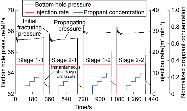
Fig. 5. Fracturing curves of multi-well zipper fracturing stimulation |
3.2. Proppant distribution in fractures
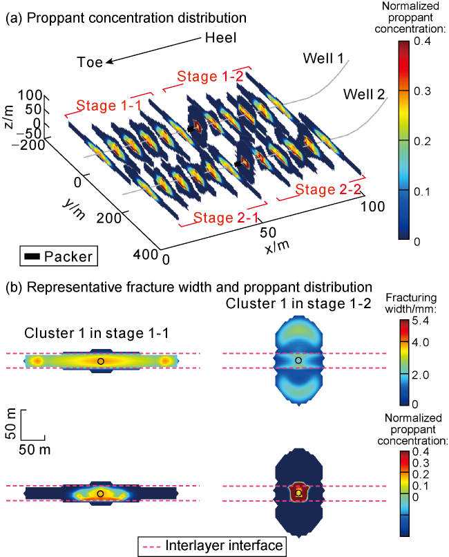
Proppant distribution determines the effectiveness of artificial fractures and has a significant impact on the effective stimulated reservoir volume and oil production. Numerical simulation results show that the propped area in a fracture is limited and the proppants are mainly concentrated in the wide fracture part near the wellbore. This is due to the formation of proppant banks at the bottom of the fracture under the effect of gravitational settlement, and the capacity of proppant transport is further inhibited as the fracture width decreases, resulting in many unpropped fractures between wells (Fig. 6a ). On the whole, the propagation of outer fractures is more dominant, their fracture length and width are larger, and the proppant transport distance and the propped area in them are larger than those in inner fractures, indicating that the capacity of proppant transport is dominated by fracture width. In addition, the proppant distribution is also as asymmetrical as the fracture wings. For example, the proppant transport distance in the negative wing of the 5th fracture in Stage 2-1 is shorter than that in the positive wing, but the proppant concentration is higher than that in the positive wing (Fig. 6b ). Fractures in any stage would break through the layer interface and propagate vertically due to stress interference. However, the high comprehensive stress of the barrier layer may reduce the fracture width and make less effective transport of proppants into the barrier layer. Instead, the proppants quickly bridge at the interface between reservoir and barrier, further hindering fluid and proppants. True triaxial sand fracturing experiments in thin interbedded shale samples have also indicated that even though hydraulic fractures can break through barrier layers, proppants cannot transport effectively due to smaller fracture width, and the overall placement range of proppants is limited, which reflects that the capacity of proppant transport is dominated by fracture width [41].
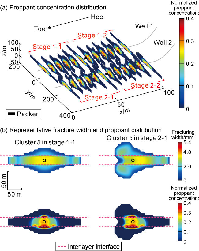
Fig. 6. Fracture geometry and proppant distribution during multi-well zipper fracturing stimulation. |
3.3. Stimulated reservoir volume
Due to different stress interference and direction, the fracture and propped areas in different stages are significantly different, and the propped ratio (propped area to fracture area) is 45%-51% (Fig. 7 ). Besides, the fracture area and propped area in the two stages in well 2 are smaller under the effect of completion sequence, and the difference in fracture area and propped area of the two wings is larger, indicating that the inter-well stress interference is not conducive to even fracture geometry and reservoir stimulation between wells. Moreover, the fracture area of Stage 1-2 is significantly larger than that of Stage 2-1, indicating that the inter-well stress interference induced more significant effects on reservoir stimulation during the zipper fracturing operation with 200 m well spacing. Therefore, it is necessary to optimize the well spacing, stage interval and cluster spacing to increase the effectively stimulated reservoir volume in multi-well pad fracturing operation.
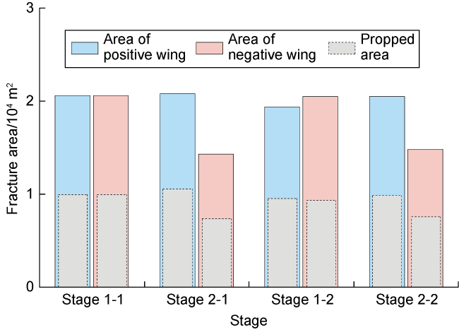
Fig. 7. Fracture area of each stage. |
4. Parametric analysis
4.1. Effect of well spacing
Well spacing is a key parameter to balance stimulated reservoir volume and economic development. The well spacing from 100-350 m was selected to simulate zipper fracturing completion and investigate the influence of well spacing on multi-fracture geometry and proppant concentration distribution. As the well spacing decreased from 200m to 100 m, the inter-well stress interference became more serious, resulting in more uneven geometry of multi-fracture propagation and proppant distribution. Especially in the two stages of well 2, the propagation of the negative wings was severely inhibited and tended to propagate longitudinally, while the lateral propagation of positive wings was more uneven. The asymmetric fractures resulted in asymmetric proppant distribution in both wings and produced more proppant bridges with higher concentration, which may increase the risk of premature screen-out. In addition, too small well spacing may result in intersection between the fractures from two wells. This may cause casing deformation and hinder subsequent fracturing treatment (Fig. 8a ). However, the inter-well stress interference decreased when the well spacing increased to 300 m. The fracture propagation became uniform and symmetrical, and no fractures hit. As a result, the fracture geometry and proppant concentration distribution are almost identical in both wells (Fig. 8b ).
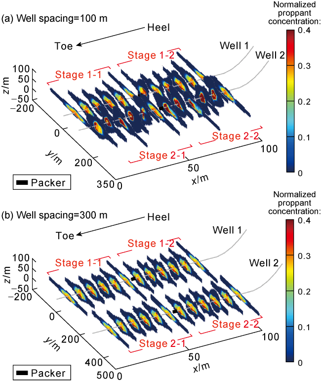
Fig. 8. Multi-fracture geometry and proppant concentration distribution at different well spacing. |
As the well spacing increased, the lateral propagation of hydraulic fractures became more uniform and the two wings became more symmetrical, resulting in a gradual increase in the total fracture area and propped area (Fig. 9 ). It indicates that the inter-well stress interference became weak with the increase of well spacing. This not only avoids fracture-driven interferences in a multi-well pad but also promotes uniform fracture propagation and proppant transport, and increase stimulated reservoir volume. However, there is an optimal well spacing in field for comprehensively considering stimulated reservoir volume and economic benefits. In order to maximize the stimulated reservoir volume, or to achieve the even geometry of fracture propagation, the reliable well spacing in this multi-well pad is 250-300 m.
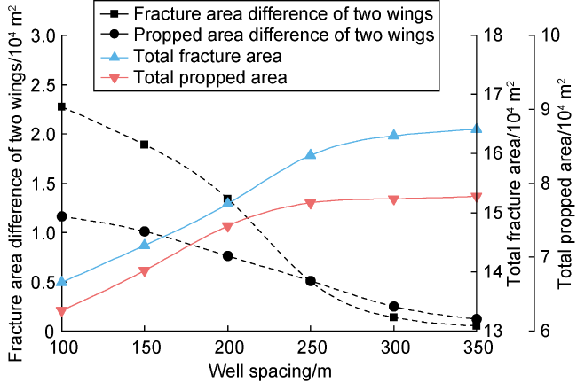
Fig. 9. Stimulated reservoir area at different well spacing. |
4.2. Effect of cluster spacing
Hydraulic fracturing test results in field indicate that a short cluster spacing can not only increase the density of artificial fractures but also significantly reduce the distance for fluid flow from reservoir matrix to fractures and the pressure driving hydrocarbon out of the matrix, which is conducive to increasing effective stimulated reservoir volume [3]. With a fixed stage interval, the number of clusters in a stage (4-8 clusters per stage) was selected to investigate the effect of cluster spacing on fracture propagation and proppant distribution. For different cluster numbers, the total fluid volume and proppant volume in a stage were converted from the same average fluid volume and proppant volume in a cluster, and other parameters remained consistent. When the number of clusters decreased from 6 to 4, the cluster spacing increased from 8 m to 12 m, resulting in a weaker stress interference. The longitudinal fracture propagation in all stages became shorter, while the lateral propagation of both wings was more adequate. The fracture propagation and proppant distribution were more uniform (Fig. 10a ). However, too large cluster spacing may cause the hydrocarbon between fractures cannot be produced, so it is critical to increasing the number of artificial fractures if necessary. When the number of clusters in a stage increased to 8, and the cluster spacing reduced to 6 m, the fracture propagation and proppant distribution became more uneven due to severer stress interference. Specifically, the propagation of exterior fractures (e.g., Cluster 8, Stage 1-1) and proppant placement became more conductive, while interior fractures (e.g., Cluster 3, Stage 1-1) tended more obvious longitudinal propagation, and their lateral propagation and proppant transport became shorter after being inhibited (Fig. 10b ). Overall, the capacity of proppant transport reduced in most fractures due to a smaller cluster spacing, resulting in less proppant placement and more proppant bridges near the wellbore.
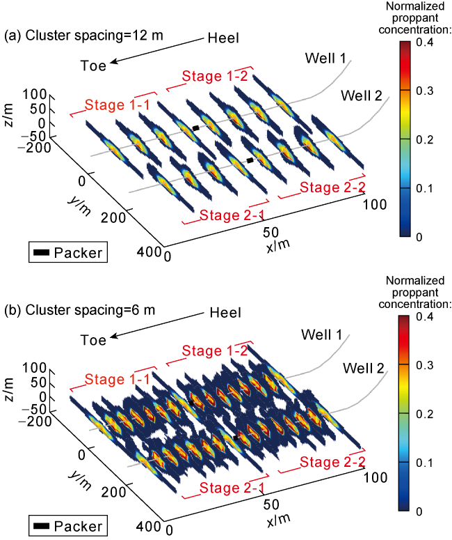
Fig. 10. Multi-fracture geometry and proppant concentration distribution at different cluster spacing. |
As the cluster spacing decreased gradually, the difference coefficient of fracture area (the ratio of standard difference of fracture area to the average value) increased obviously, indicating more uneven fracture propagation. Although the total fracture area and the propped area gradually increased as the cluster spacing decreased, the propped area became stable when the cluster spacing was less than 7 m (Fig. 11 ). Therefore, even though closely- spaced hydraulic fractures can increase the fracture area, a short cluster spacing would enhance the stress interference, which inhibits the propagation and width of interior fractures and reduces the capacity of proppant transport in the fractures. It indicates that simply shortening the cluster spacing cannot effectively enlarge propped area, but will increase the proppant concentration near the wellbore, resulting in the occurrence of proppant screen-out and sand production.
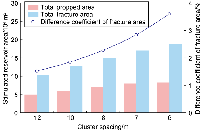
Fig. 11. Stimulated reservoir area at different cluster spacing. |
The production data of shale oil horizontal wells after hydraulic fracturing stimulation show that cluster spacing is strongly correlated with stimulated reservoir volume and economic benefits, and well productivity and ultimate recovery can be significantly improved by properly shortening cluster spacing. However, too short cluster spacing would slow down the increase of production and increase investment cost [42]. To maximize the economic benefits by inducing closely-spaced hydraulic fractures, it is necessary to make even and wide fractures and effective proppant transport. This can be realized by limiting fracturing fluid rate and temporarily plugging and diverting technologies [43-44].
4.3. Effect of time interval
After the completion of fracturing treatments, fractures induced at different stages tend to close under the action of compressive stress, and the stress interference becomes small and weak. To investigate the effect of time interval on fracture propagation and proppant distribution, with the same fracturing parameters of the basic case, the original zipper fracturing operation changed to sequential fracturing, namely Stage 1-1→Stage 1-2→Stage 2-1→Stage 2-2. Compared with the original zipper fracturing, sequential fracturing reduces the time interval between stages of one well to zero while delaying that of the other well to the entire treating time of the counterpart. The simulation results showed that the toe fractures in late stages (such as Cluster 1 in Stages 1-2) were severely inhibited and tended to propagate vertically; and small fracture width restricted proppant transport, and resulted in a smaller area of proppant placement and more proppant bridges with higher concentration near the wellbore, increasing the risk of premature screen-out (Fig. 12 ). This is because the fracturing time interval in one well is shorter, so that fracturing fluid in previous fractures is not sufficiently leak-off, resulting in higher fluid pressure and severer stress interference on new fractures. The results of true triaxial hydraulic fracturing experiment also indicate that the higher the fluid pressure in previous fractures, the more obvious the influence of stress interference on late fracture propagation [45]. Although the time interval between adjacent wells is small in zipper fracturing, controlled by well spacing, the inter-well stress interference is less than that in sequential fracturing. In conclusion, zipper fracturing not only enhances fracturing efficiency but also reduces inter-stage stress interference, therefore promoting more uniform fracture propagation and proppant distribution.
Fig. 12. Multi-fracture geometry and proppant concentration distribution in sequential fracturing. |
5. Conclusions
Fracture initiation and propagation during zipper fracturing operation are affected by inter-cluster, inter-stage, and inter-well stress interferences, and the fracture morphology is characterized by uneven distribution, asymmetric wings and heel bias.
The proppant transport is dominated by fracture geometry and width. Proppants are mainly concentrated near the wellbore where the fracture width is larger, and they are easy to accumulate and bridge quickly at the narrow part such as fracture tip and interlayer interface, which further hinders fluid flow. Generally, the propped area is only 45%-51%.
Increasing well spacing is helpful to reducing inter-well stress interference and promoting the uniform distribution of fractures and proppants in two wings. There is an optimal well spacing in field to get the maximum stimulated reservoir volume and even fracture propagation.
Stimulated reservoir volume can be improved by shortening cluster spacing appropriately, but too short cluster spacing is not conducive to get uniform fracture geometry and proppant distribution, resulting in smaller propped areas and greater risk of proppant screen-out. There is an optimal cluster spacing in multi-well pad fracturing treatment.
Increasing fracturing time interval is conducive to closing previous fractures and reducing inter-stage stress interference. Zipper fracturing treatment provides more uniform fracture propagation and proppant distribution than sequential fracturing treatment.
Nomenclature
a—proppant radius, m;
A—influencing coefficient matrix, Pa/m;
B—blocking function, dimensionless;
Cd—discharge coefficient, dimensionless;
Dp—perforation diameter, m;
Dw—wellbore diameter, m;
E—Yong’s modulus, Pa;
E°—Young’s modulus of plane strain, Pa;
g—acceleration of gravity, m/s2;
G—shear modulus, Pa;
${{\hat{G}}_{\text{p}}}$—the function of proppant gravitational settlement, dimensionless;
i—number of perforation clusters;
I33, I333—partial derivative of Green function I [24];
KIC—fracture toughness, Pa·m0.5;
Lc—cluster spacing, m;
N—number of clusters per stage;
Np—number of perforations;
p—fluid pressure in fractures, Pa;
p—column vector of fluid pressure in fractures, Pa;
pc—wellbore friction, Pa;
pf—fracture inlet pressure, Pa;
pp—perforation friction, Pa;
pw—bottom hole pressure, Pa;
qp—proppant flux per unit length, m2/s;
qs—fluid flux per unit length, m2/s;
Q—injection rate, m3/s;
Qi—injection rate of cluster i, m3/s;
${{{Q}'}_{i}}$—flow rate between cluster i and cluster i-1, m3/s;
${{\hat{Q}}_{\text{p}}}$—function of proppant advection, dimensionless;
${{\hat{Q}}_{\text{s}}}$—function of capturing fluid flow from Poiseuille’s flow to Darcy’s flow, dimensionless;
r—length to fracture tip, m;
R—penny fracture radius, m;
t—time, s;
${{v}_{\text{tip}}}$—propagation velocity of fracture tip, m/s;
μ—fluid viscosity, Pa·s;
v—Poisson’s ratio;
vL—leak-off rate, m/s;
w—fracture width, m;
w—column vector of fracture width, m;
wc—critical width of fracture propagation, m;
x, y, z—global coordinate, m;
x3—local coordinate, m;
σ33—normal stress in the local coordinate, Pa;
${{\sigma }_{\text{h}}}$—column vector of minimum horizontal principal stress, Pa;
δ—dirac delta function, m−2;
$\bar{\phi }$—normalized proppant concentration, dimensionless;
${{\phi }_{0}}$—normalized proppant injection concentration, dimensionless;
Δρ—density difference between proppant and fluid, kg/m3;
ρ—density of proppant-carrying fluid, kg/m3.