

Introduction
Deep shale gas will be the focus in future natural gas exploration and development in China [1-2], and horizontal well and staged fracturing technology are the key to the effective development of deep shale gas [3-4]. However, casing deformation (CD) has not been well solved, thus restricting the large-scale and effective development of deep shale gas. CD events occurring in deep shale gas wells in the Luzhou block in southern Sichuan Basin had been up to 51.0% by December 2022, of which 68.6% in the L203 well block, and 45.7% of CD wells were not fractured (well deformed before fracturing, WDBF in brief). This badly affects the fracturing effect.
A lot of researches have been made on CD in shale gas wells in the Sichuan Basin [5⇓⇓-8]. It’s found that CD in horizontal wells is directly related to natural fracture-activated slip and concluded that the in-situ stress field, fracture strike, and pore pressure are the major factors affecting fracture stability. Meanwhile, scholars have conducted numerical simulation and casing shear deformation experiments to find out the following two measures to reduce CD events [9⇓⇓⇓-13]: (1) Lower the risk of fault slip by temporary fracture plugging and multi- cluster perforation to control and reduce fluid pressure increment. (2) Enhance the casing shear strength by increasing the casing wall thickness and steel grade, and reducing cement sheath elastic modulus. The above measures have been tested on-site in areas such as Weiyuan and Changning, and achieved certain results [6]. Compared with middle-deep reservoirs such as the Changning block, deep reservoirs such as the L203 well block have more developed fractures, higher formation pressure, and the stress transitions from strike-slip to strike-slip/reverse faulting. Therefore, the L203 well block suffers from more serious CD with an obvious WDBF problem, and has a higher level of CD and an average influence length of 857 m, which is much greater than that in the middle-deep formation. At present, the CD mechanism in the Luzhou block, especially the CD mechanism of massive WDBF, is still unknown, so it is urgent to predict CD risks.
To effectively solve the CD during the fracturing of shale gas horizontal wells, this paper adopts geological, seismic and logging data to characterize fractures and shear slip of casing, plots risk assessment charts of CD for the Luzhou block, and develops well-directed measures for avoiding CD risks, hoping to provide technical support for the effective and large-scale development of deep shale gas.
1. Casing deformation
1.1. Deformed-before-fracturing phenomenon
The Luzhou block currently consists of two production well blocks mainly: L203 and Y101. CD events happened by 68.6% in L203, and 45.7% of the CD wells have deformed before fracturing. CD events happened by 34.0% in Y101, and 8.8% of the CD Wells have deformed before fracturing. The original inner diameter of the casing in the Luzhou block is 114.3 mm. CD can be graded into A, B and C levels according to the inner diameter, among which the inner casing diameter of A-level is greater than 85 mm, that of B-level is 54-85 mm, and that of C-level is less than 54 mm. Small bridge plugging and multi-stage combined fracturing can be applied to deal with A-level and B-level CD. C-level CD is too severe that fracturing operation has to suspend at present. Among 104 wells in Luzhou block, A-level, B-level and C-level account for 41.3%, 32.7% and 26.0%, respectively. In addition, 51.4% of the 35 WDBF are C-level. The CD event rate is high in the study area, and with a serious deformed-before-fracturing problem, resulting in the temporary loss of productivity of some wells.
1.2. Frequent casing deformation events occuring in platform
Among 123 fractured wells in the study area, 26 of them are appraisal wells and 97 are platform wells. The CD event rate of platform wells is 48.5%, and that of appraisal wells is 23.1%. Among all CD wells, platform wells account for 88.7%. In Luzhou block, frequent CD events occur in platform.
1.3. Concentrated distribution of casing deformation points
The distribution results of 162 CD points in 70 wells in Luzhou block show that they are mainly located near point A (the first target point entering the design target layer after deflecting well trajectory) and around the central location of the horizontal section. In the horizontal section, 46.9% of the CD points are located within 400 m from Point A, while 30.9% are 800 m to 1200 m from Point A.
1.4. Types of casing deformation
The MIT24 caliper logging data is used to analyze the CD types in the study area. The angle between the long axis direction and the due north direction after CD is defined as the shear angle of CD. The statistical results of 88 CD points in 20 wells in Luzhou block show that the shear angle of CD is 20°-65°, of which 50.1% is larger than 45°.
2. Main influencing factors of casing deformation
2.1. In-situ stress state
In-situ stress state is a key factor in fracture activation. Stress factors can provide continuous and quantitative characterization of stress mechanisms in formation [14-15]. Five common stress mechanisms in reservoirs include three classical Anderson’s faulting modes (normal faulting, strike-slip faulting, and reverse faulting) and two common intermediate stress states (normal/strike-slip faulting and strike-slip/reverse faulting).
After evaluating the fault slip caused by different stress mechanisms, it is found that strike-slip faulting is more likely to cause CD than reverse faulting and normal faulting (Fig. 1a ). In addition, the larger the stress factor in strike-slip faulting, the smaller the force required to slip by 10 mm and the higher the CD risk (Fig. 1b ). According to the analysis of the stress state in the southern Sichuan Basin, both deep and middle-deep shale reservoirs follow the mechanism of strike-slip faulting. However, their stress factors vary. The stress factor is the highest, and the CD event rate reaches 68.6% in the L203 well block (Table 1 ).
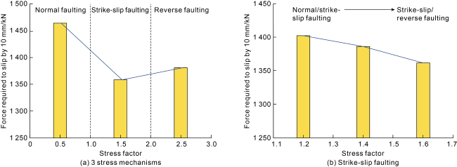
Fig. 1. Stress mechanisms and difficulty degree in fault slip. |
Table 1. Stress factors of typical wells in different blocks |
| Block | Well block | Well | Stress factor | Stress mechanism | CD event rate/% | |
|---|---|---|---|---|---|---|
| Single well | Average | |||||
| Luzhou | L203 | L203 | 1.52 | 1.54 | Strike-slip | 68.6 |
| H57-3 | 1.55 | Strike-slip | ||||
| Y101 | H2-7 | 1.62 | 1.40 | Strike-slip | 34.0 | |
| H10-3 | 1.18 | Strike-slip | ||||
| Yuxi | H202 | H202 | 1.33 | 1.34 | Strike-slip | 22.2 |
| H205 | 1.34 | Strike-slip | ||||
| ZU203 | Zu201 | 0.29 | 0.68 | Normal | 0 | |
| Zu207 | 1.07 | Strike-slip | ||||
| Weiyuan | Zi201 | Zi203 | 0.57 | 0.49 | Normal | 48.6 |
| Zi201 | 0.41 | Normal | ||||
| W204 | W213 | 1.60 | 1.52 | Strike-slip | ||
| W214 | 1.44 | Strike-slip | ||||
2.2. Fracture strike
The study area has undergone three tectonic movements since the Mesozoic, forming the present tectonic pattern and fracture system [16]. The tectonic fracture strike is shown in a rose diagram (Fig. 2a ). The Fuji syncline of the L203 well block develops four groups of tectonic fractures: NE-SW, NW-SE, NNW-SSE, and nearly S-N. The complex fracture system developed in L203 is possible to be activated and induce CD during hydraulic fracturing. The fracture closest to the wellbore is used as the associated fracture, and the correlation between the associated fracture azimuth and CD is analyzed (Fig. 2b ). The azimuth of fracture triggering severe CD is 60°-80°, and the 60°-azimuth corresponds to the highest CD rate. That is to say, CD in L203 is related to the fracture azimuth, and the 60°-azimuth fractures are most dangerous to induce CD events.
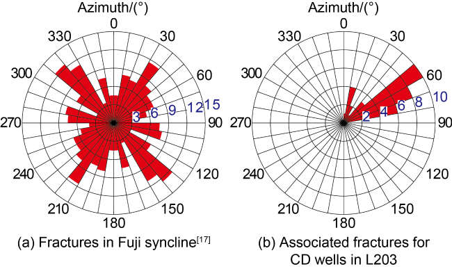
Fig. 2. Rose diagram of fracture azimuth (the radial data represents the number of fractures in a certain azimuth range). |
2.3. Main influencing factors
According to microseismic monitoring results in the study area, the multi-branch wells in platform are prone to activate adjacent fractures during the multi-stage fracturing process, thus triggering shear slip and causing severe CD near the fractures, and the CD points are generally far away from the target section to be fractured [13]. As mentioned above, 50.1% of CD points have a CD shear angle greater than 45°, and the 60°-azimuth fractures are the most possible to induce CD, so it’s tentatively concluded that fracture shear slip is the main influencing factor for CD. As shown in Fig. 3 , platforms H55 and H75 are distributed on both sides of Fracture F8. Platform H75 has four branch wells. During the sequential fracturing in branched wells 2, 3, and 4, the fracturing fluid activated the Fracture F5 in northwest of Platform H75. Three repeated activation effects act upon platforms H55 and H51, and then cause serious CD in the Well 4 of Platform H55 and Well 3 and Well 4 of Platform H51. When fracturing on Platform H56, Fracture F1 was activated, resulting in severe CD in wells 1 and 2 on Platform H56 and Well 2 of Platform H51. Similarly, when the upper branches of Platform H55 were fractured, Fracture F3 was activated, triggering serious CD in the Well 1 of Platform H51 which intersects with Fracture F3. In summary, the severe CD wells in the L203 well block are distributed mainly in the active fracture zone, and the CD is mainly caused by fracturing of adjacent wells. Therefore, the activation of natural fractures in the formation can explain why many wells in this well block get deformed before fracturing.
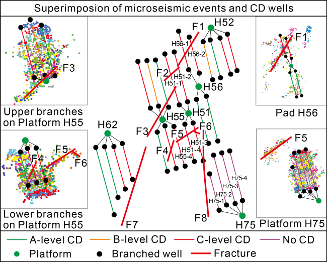
Fig. 3. Superposition of fracturing microseismic events distribution and CD wells in L203 well block (colored dots represent microseismic events). |
3. The mechanism and value of casing deformation
In the original ground stress state, fractures are in a relatively stable state, and the friction force on the fracture surface is greater than the shear stress. As the fracturing fluid is continuously injected into the formation, the pore pressure rises constantly and the friction force on the fracture surface drops constantly. Fracture stability reaches the critical state when the friction force is equal to the shear stress. As more fracturing fluid is injected, the fracture will become unstable, and trigger CD. In view of this, it is necessary to build an integrated stress-fracture-wellbore evaluation method based on present stress state, fracture development characteristics, and fracturing parameters to analyze the CD problem. The evaluation method consists of the following three aspects: (1) Collect regional fracture information and evaluate fracture stability; (2) Analyze the forces on unstable fractures and calculate fracture slippage; (3) Adopt finite element method to transform the fracture slippage into CD value.
3.1. Analysis of fracture stability
Fractures are mechanically weak surfaces embedded in the rock and are more prone to rupture than the rock. Assuming that an fracture approximate angle (α) denotes the angle between the fracture surface and the direction of the maximum principal stress and parallels the vertical stress, we can express the normal stress on the fracture surface under the original stress conditions as [7]:
${{S}_{\text{n}}}=0.5\left( {{\sigma }_{1}}+{{\sigma }_{3}} \right)-0.5\left( {{\sigma }_{1}}-{{\sigma }_{3}} \right)\cos \left( 2\alpha \right)$
The shear stress can be expressed as:
${{\tau }_{xy}}=0.5\left( {{\sigma }_{1}}-{{\sigma }_{3}} \right)\sin \left( 2\alpha \right)$
The effective normal stress on the fracture surface accords with the Terzaghi’s law:
${{\sigma }_{\text{n}}}={{S}_{\text{n}}}-{{p}_{\text{p}}}$
When the shear stress on the fracture surface is greater than the friction force, the rocks on both sides of the fracture begin to slip, which is consistent with the Amonton’s theorem. Note that the fracture cohesion is 0 [15]:
${{\tau }_{xy}}\ge \mu {{\sigma }_{\text{n}}}$
During fracturing operation, fluid is continuously injected into the formation to break the formation equilibrium. The critical pore pressure increment (pw) to discern the fracture activation and destabilization is:
${{p}_{\text{w}}}={{\sigma }_{3}}-{{p}_{0}}+\left( {{\sigma }_{1}}-{{\sigma }_{3}} \right)\left( {{\sin }^{2}}\alpha -\frac{1}{\mu }\sin \alpha \cos \alpha \right)$
According to Eq. (5), the ground stress, fracture occrurrence, and pore pressure are major factors affecting the difficulty degree of fracture activation. For Well L203, σ1=109.6 MPa, σ2=101.3 MPa, σ3=93.6 MPa, p0=80 MPa. As shown in Fig. 4a , in the original ground stress state, the fracture is most easily activated when fracture approximate angle is 30°, and most difficult to be activated when fracture approximate angle is 90°. Under the current ground stress field, the shear stress on the fracture surface is constant, and continuous injection of fracturing fluid causes a drop in the shear strength. When pp is 80 MPa, the shear strength of the rock is greater than the shear stress, and fractures at all angles are in a stable state. When pp is 90 MPa, fractures at 10°-50° are activated. When pp is 110 MPa, fractures at all angles are activated (Fig. 4b ).
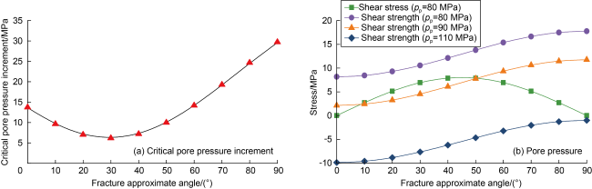
Fig. 4. Relationship between fracture approximate angle and fracture stability. |
According to the analysis results of the stability of the natural fractures in Well L203 (Fig. 5 ), the fractures are all stable in the original ground stress state, 47.7% of the fractures are activated when pw=8 MPa and 86.4% of the fractures are activated when pw=10 MPa. The risk of fracture activation in Well L203 is high, and 10 MPa increment of pore pressure can activate more than 85% of the fractures.
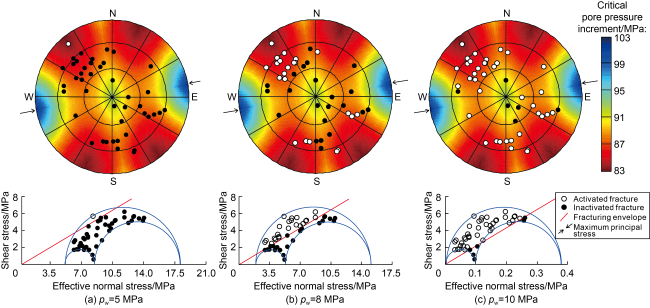
Fig. 5. Stability analysis of natural fractures in shale reservoir in Well L203. |
3.2. Calculation of fracture slippage
Based on the theory of complex function, fracture slippage can be calculated by combining the regional stress state and the correlation between fracture and rock mass [18]. During fracturing operation, fractures may be activated for several times. Therefore, it is necessary to comprehensively consider the fracture development characteristics in the study area, and then determine the slip frequency and the single slip distance [8], and finally calculate the total slip distance of the fracture surface by the following equation:
$\Delta u=\sum\limits_{i=1}^{n}{{{u}_{\text{f,}i}}}$
For a single slip, pore pressure, fracture radius, fracture location and fracture approximate angle are four major factors affecting the slippage. Fig. 6 shows the relationship between fracture slippage and fracture approximate angle under the influences of different sensitivity factors. Under the same ground stress condition, the larger the pore pressure, the larger the fracture slippage is; the larger the fracture radius, the larger the fracture slippage is; and the farther away from the fracture center, the smaller the slippage becomes.
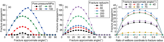
Fig. 6. Relationship of sensitivity factors and fracture slippage. |
3.3. Calculation of casing deformation value
The pore pressure of the CD section of Well H55-4 is 95 MPa, and fracture approximate angle is 14.68°. Fig. 7 shows the relationship between fracture slippage and fracture approximate angle of Well H55-4. It can be seen, fracture slippage is the largest when fracture approximate angle is 30.00°, and fracture slippage is 5.78 mm when fracture approximate angle is 14.68°. Based on Eq. (6), shear activation occurred three times in the well, resulting in a total fracture slippage of 17.34 mm.
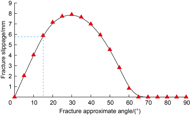
Fig. 7. Relationship of fracture slippage and approximate angle in Well H55-4. |
However, fracture slippage cannot be equated with the CD value [19]. The finite element numerical simulation method should be used to transform fracture slippage into the CD value. The Well H55-4 is taken as a case, fracture slippage is 17.34 mm. Under the displacement load condition, a formation-fracture-wellbore coupled numerical model was established (Fig. 8a ). In the model, the borehole diameter is 215.9 mm, the casing outer diameter is 139.7 mm, and the casing wall thickness is 12.7 mm. Moreover, to reduce boundary effect, the formation cross-section is set to be not less than 5 times the borehole, and the angle between fracture and casing is taken as 72.45° according to the microseismic and ant-body interpretation results. Fig. 8b shows the relationship between fracture slippage and CD value based on the coupled numerical model. CD value is 13.1 mm when fracture slippage is 17.34 mm.
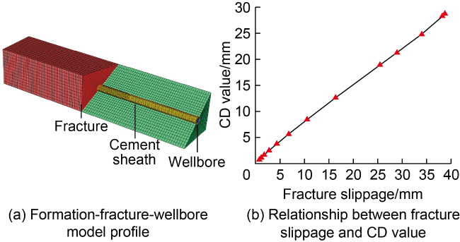
Fig. 8. Numerical model of formation-fracture-wellbore and the conversion from fracture slippage to casing deformation value. |
3.4. Evaluation of model accuracy
The dual cross-validation method was adopted to validate the accuracy of the model results. The microseismic intensity information was used to validate the accuracy of fracture slippage. MIT24 multi-arm caliper logging data was used to evaluate the accuracy of the CD value.
3.4.1. Verification of fracture slippage
Microseismic activity follows the G-R equation [20]:
$\left\{ \begin{array}{*{35}{l}} \lg N=a-b{{M}_{\text{w}}} \\ b=\frac{1}{2.3({{M}_{\text{wav}}}-{{M}_{\text{w}\min }})} \\ \end{array} \right.$
Calculate the microseismic magnitude to get the seismic moment [21]:
$\left\{ \begin{array}{*{35}{l}} {{M}_{0}}=G(\pi {{r}^{2}})D \\ {{M}_{\text{w}}}=\frac{2}{3}\left( \lg {{M}_{0}}-9.1 \right) \\ \end{array} \right.$
The model proposed by Brune [22] for calculating the radius of circular fractures is applied to obtain the fracture slip distance:
$\left\{ \begin{array}{*{35}{l}} r=\sqrt[3]{\frac{7{{M}_{0}}}{16\Delta \sigma }}=\sqrt[3]{\frac{7\times {{10}^{1.5{{M}_{\text{w}}}+9.1}}}{16\Delta \sigma }} \\ D=\frac{16}{7}\frac{\Delta \sigma r}{\pi G} \\ \end{array} \right.$
There are four branched wells on Platform H75. During the sequential fracturing on wells 2, 3, and 4, the microseismic moment magnitudes of fracture slip in Platform H55 are 1.81, 1.95, and 1.88, respectively, the fracture radius is 73-82 m, and the corresponding fracture slippage is 4.83, 5.68 and 5.24 mm, respectively. After three times of fracture activation, the fracture slippage in Well H55-4 is 15.75 mm, with a relative error of 10.09% with the model result, indicating that this model is effective for calculating fracture slippage.
3.4.2. Verification of casing deformation value
According to the MIT24 multi-arm caliper logging results, the CD occurred at 4592.747 m in Well H55-4, with the greatest CD value of 14.9 mm. The error between model result and logging result is 12.08%, indicating the model is reliable in calculating the CD value.
4. Prevention and control measures of casing deformation
4.1. Fracture risk assessment chart
Theoretically, the CD risk is related to fracture connectivity, fracture slippage, and times of fracture activation [19]. Therefore, the comprehensive influence of fracture activation risk and fracture slippage should be fully considered in designing well spacing. Fractures in the study area were characterized according to ant-body fracture interpretation and microseismic monitoring data. Furthermore, the fracture risk was assessed based on the characterization and ground stress data. The fracture activation risk can be calculated by the following equation.
${{p}_{\text{i}}}=\frac{{{p}_{0}}}{{{p}_{\text{p}}}}$
For comparison purposes, pi is normalized:
${{M}_{\text{i}}}=\frac{{{p}_{\text{i}}}-{{p}_{\text{i}\min }}}{{{p}_{\text{i}\max }}-{{p}_{\text{i}\min }}}$
According to the essential data of the L203 well block, 277 fractures were characterized, and the fracture activation risk and fracture slippage were evaluated for each fracture (Fig. 9 ). As can be seen from Fig. 9a , fractures with activation risk greater than 0.8 account for 66.06%, and most of them are distributed in the edge of the block. Fractures with slippage of 0-45 mm account for 74.37%, mostly distributed on the middle of the block, and those with slippage larger than 45 mm are mainly found on the margin (Fig. 9b ). Fractures with approximate angle generally ranged between 10° and 50° accounting for 65.34%, and with activation risk higher than 0.8, critical pore pressure increment of 6.05-9.71 MPa (Fig. 10 ), indicating that fractures in the L203 block have a high activation risk.
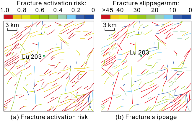
Fig. 9. Fracture activation risk assessment chart of L203 well block. |
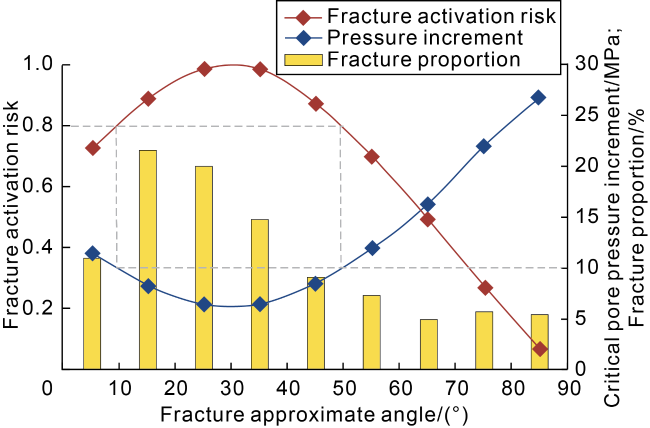
Fig. 10. Quantitative evaluation of fracture activation risk in L203 well block. |
4.2. Prevention and control measures of casing deformation and their effects
4.2.1. Geological factors
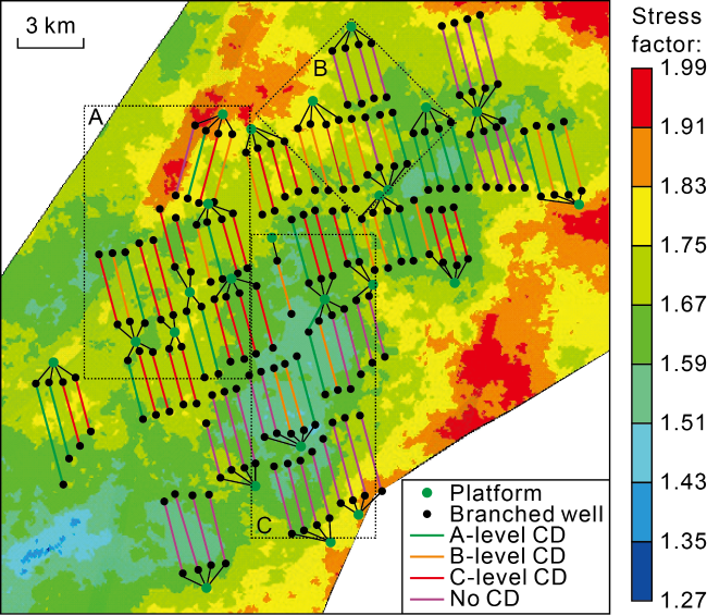
Fig. 11. Distribution of casing deformation wells and stress factors in L203 well block. |
Besides the stress mechanism, fracture development is another factor causing CD. Compared with the middle- deep formations, deep formations in Luzhou block have more developed fractures and more serious CD. Seismic interpretation is often used to describe large-scale fractures, but cannot finely characterize small-scale fractures. However, small-scale fractures are necessary ones for connecting with distal fractures. The ant-body fracture interpretation information and microseismic data can be combined to characterize small-scale fractures. The fracture distribution chart of L203 well block shows that fracturing-activated fault slip is a main factor causing the CD in this block, so it’s better to locate wells in zones with low fracture development degree (Fig. 9 ).
4.2.2. Engineering factors
(1) Avoiding high-risk fractures and fracture centers. Based on the accurate characterization of regional fractures, it is essential to avoid risky fractures, including high activation risk and high slippage risk, in well deploying to reduce CD risk. Slippage is different on different points in the same fracture. Slippage reaches the maximum on the center of an active fracture, and gradually decreases from the center to the edge. If risky fractures are unavoidable, wells should be deployed in places away from the center.
(2) Optimizing the wellbore parameters. When risky fractures are unavoidable, it is essential to optimize wellbore parameters to enhance the shear strength of the casing. According to existing studies, measures such as small-size casing and lowering cement sheath elastic modulus have limited effects on solving the CD problem [23]. According to the wellbore orientation sensitivity analysis (Fig. 12 ), changing the wellbore orientation could reduce the risk of CD. When fracture approximate angle is 0° and 90°, or fracture is parallel to the wellbore, the casing shear stress is 0, with no risk of shear CD. When fracture is perpendicular to the wellbore, the shear stress is the highest and with the highest risk of CD. To guarantee the effect of fracturing, the wellbore is generally drilled perpendicular to the direction of the maximum horizontal principal stress, and the wellbore orientation could be adjusted within 30° (Fig. 12a ). As shown in Fig. 12b , the reduction degree of the casing shear stress increases with the increase of fracture approximate angle. When fracture approximate angle is 60°-90°, the wellbore orientation could be adjusted to eliminate the shear stress acting on the casing. As mentioned in the previous section, the fracture approximate angle in L203 well block ranges from 10° to 50°. The casing shear stress could drop by 22.21% to 72.98% by adjusting the wellbore orientation in this range. Therefore, when the fractures with risk cannot be avoided, the wellbore orientation can be adjusted to mitigate the CD.
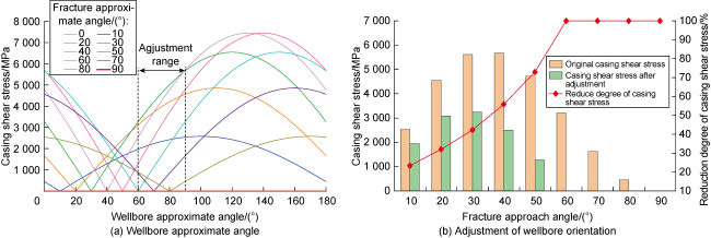
Fig. 12. Prevention and control measures for wellbore (the wellbore approximate angle is the angle between the horizontal wellbore and the maximum principal stress). |
(3) Optimizing the well structure. Stress concentration generally takes place in the curved section of a horizontal well. The smaller the curvature radius of the borehole, the higher the risk of CD is. As shown in Fig. 13 , when the curvature radius is less than 200 m, the casing stress rises rapidly with the decrease of the curvature radius. And the larger the stress difference, the faster the rise of the casing stress, resulting in a higher risk of CD during fracturing. When the curvature radius is greater than 200 m, the casing stress is not subject to the influence of the curvature radius and stress difference. Therefore, it is necessary to ensure that the curvature radius of the curved section of horizontal well is greater than 200 m when drilling in high-quality reservoirs.
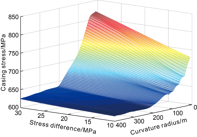
Fig. 13. Influence of stress difference and borehole curvature on casing stress. |
(4) Optimizing the fracture parameters. Ground stress is the internal cause of fracture activation, while fracturing operation is the external cause of fracture activation. It is effective to prevent CD by controlling the pore pressure increment and reducing fracture risk and slippage. Specifically, the pore pressure within fractures can be reduced by increasing the evasive distance or lowering the single-operation pressure. In addition, it is also an effective measure for lowering CD risk by increasing the stage length and mitigating the influence of stress accumulation on the fracture.
4.2.3. Implementation effect
The threshold of pore pressure increment is low in L203 well block, so the fractures have a high activation risk. While ensuring the fracturing effect, it is feasible to reduce the pore pressure increment to lower the fracture activation risk. Considering the relationship between fracture, wellbore and stress, differentiated fracturing construction scheme was adopted on H7 platform (Table 2 ). The CD event is prevented and controlled by reducing the pump rate, fracturing fluid volume and proppant concentration when fracturing the fracture zone with a high activation risk. The average number of CD points on Platform H7 decreased by 62.5% after optimization, indicating the measures are effective for preventing and controlling CD.
Table 2. Differentiated fracturing construction scheme in Luzhou block |
| Wellbore-fracture | Risk | Stage length/m | Pump rate / (m3•min−1) | Fluid volume/ (m3•m−1) | Proppant concentration/ (t•m−1) | |
|---|---|---|---|---|---|---|
| Pattern | Schematic | |||||
| No fracture |  | Low | 50-70 | 16-18 | >25 | >3.0 |
| Parallel |  | Low | 50-70 | 16-18 | >30 | >3.0 |
| Oblique |  | High | 70-80 | 14 | 25 | 2.5 |
| Vertical |  | High | ≥80 | 14 | 20 | 2.0 |
|
 Maximum horizontal principal stress
  Fracture
  Wellbore
5. Conclusions
Fracturing-activated fault slip is a main factor causing CD events in deep shale gas wells in the Luzhou block, southern Sichuan Basin. In the study area, the fracture approximate angle is primarily 10°-50°, accounting for 65.34%, and the critical pore pressure increment for fracture activation is 6.05-9.71 MPa.
The CD caused by geological factors can be prevented and controlled by avoiding the faults with risks and deploying wells in areas with low value of stress factor. The CD caused by engineering factors can be prevented and controlled by: (1) keeping wells avoid faults with risks of activation and high slippage, or deploying wells in areas far from the faulting center if such avoidance is impossible; (2) optimizing the wellbore parameters, adjusting the wellbore orientation to reduce the shear force on casing to a certain extent and thus mitigate the CD; (3) optimizing the casing program to ensure that the curvature radius of the curved section of horizontal well is greater than 200 m while the drilling rate of high-quality reservoirs is not impaired; (4) optimizing the fracturing parameters, increasing the evasive distance, lowering the single-operation pressure, and increasing the stage length, which can help effectively reduce the risk of CD.
Nomenclature
a—constant, dimensionless;
b—the slope of the G-R formula, dimensionless;
D—fracture slippage, m;
G—rock shear modulus, Pa;
i—times of fracture slip, dimensionless;
Mi—normalized risk of fracture activation, dimensionless;
M0—seismic moment, N·m;
Mw—microseismic moment magnitude, dimensionless;
Mwav—average moment magnitude, dimensionless;
Mwmin—minimum microseismic moment magnitude, dimensionless;
n—total number of fracture slip, dimensionless;
N—number of microseismic events less than Mw, dimensionless;
p0—original formation pressure, MPa;
pi—risk of fracture activation, dimensionless;
pp—pore pressure at fracture activation, MPa;
pw—critical pore pressure increment for fracture activation, MPa;
pimax, pimin—maximum and minimum fracture activation risks, dimensionless;
r—fracture radius, m;
Sn—normal stress on fracture surface, MPa;
α—fracture approximate angle (the angle between fracture and maximum principal stress direction), (°);
Δu—relative tangential fracture slippage, m;
Δuf,i—relative tangential slippage at the ith activation, m;
Δσ—stress drop after the release of seismic energy, Pa;
μ—friction coefficient on fracture surface, 0.6-1.0, dimensionless;
σ1, σ2, σ3—maximum, intermediate and minimum principal stresses, Mpa;
σn—effective normal stress on fracture surface, Mpa;
τxy—the shear stress caused by ground stress acting on fracture surface, MPa.