

Introduction
Hot dry rock (HDR) geothermal resources are abundant and widely distributed, offering a unique advantage as a clean and renewable energy source [1⇓-3]. The primary technology for developing HDR resources is enhanced geothermal system (EGS), which involves creating artificial heat reservoirs through hydraulic fracturing to increase the permeability of geothermal reservoirs. This method establishes highly conductive heat exchange channels, enabling efficient and economical heat extraction [4-5]. In conventional hydraulic fracturing, the continuous injection of fracturing fluid raises the bottomhole pressure above the reservoir breakdown pressure, creating artificial fractures. However, the HDR reservoir stimulation process faces challenges, such as high breakdown pressure and single fracture geometries, which severely limit efficient heat extraction. Furthermore, the high breakdown pressure encountered in actual development processes can even trigger seismic activity [6⇓-8]. HDR soft fracturing techniques offer the potential to reduce breakdown pressures and increase the stimulated reservoir volume (SRV), supporting the efficient and safe development of HDR resources for economic and effective geothermal energy extraction [9-10].
Soft hydraulic fracturing, also known as cyclic or fatigue hydraulic fracturing, is an innovative fluid injection method that uses cyclic injection to maintain fluid pressure below the rock breakdown pressure. This creates cyclic loading at the wellbore, subjecting the rock to repeated loading-unloading processes, which gradually deteriorates its mechanical properties and induces rock fatigue damage. This approach helps to reduce the fracture initiation pressure, form complex fracture network, and mitigate the risk of induced seismicity [11-12]. Li et al.[13-14] investigated the evolution of fracture morphology in coal rock under cyclic hydraulic fracturing. Their results indicated that multiple fracture planes formed within the coal rock under cyclic loading, creating a complex fracture network, with the minimum cyclic pressure being 85% of the conventional continuous injection pressure. Zhai et al. [15] conducted laboratory experiments on coal rock using soft hydraulic fracturing under varying cyclic parameters (frequency and pressure). They found that under cyclic loading, coal rock pores underwent periodic “compression-expansion-compression” effects, leading to fatigue damage and the formation of a fracture network. Wei et al. [16] investigated the characteristics of sandstone strength deterioration and rock fracture mechanisms under various pulse water pressures through laboratory experiments and numerical simulations. They obtained deterioration curves of sandstone tensile strength under these conditions. Zang et al. [17⇓-19] compared the injected energy with seismically released energy and found that soft hydraulic fracturing can reduce the total number of induced events and the likelihood of higher-magnitude events. They also discussed the application of this injection method in geothermal reservoirs. In subsequent studies, Zang et al. [6] conducted laboratory and field experiments on granite, confirming that soft hydraulic fracturing can lower the breakdown pressure, alter rock fracture patterns, and enhance reservoir permeability. Zhuang et al. [20] conducted true triaxial hydraulic fracturing experiments on granite under six injection methods: constant-rate continuous injection, stepwise rate continuous injection, cyclic progressive injection, stepwise pressurization, stepwise pulse pressurization, and cyclic pulse pressurization. The cyclic pulse pressurization method showed a potential for controlling hydraulic fracture propagation. Zhuang et al. [21] further studied soft hydraulic fracturing of granite under different cyclic pressure ratios, revealing that soft hydraulic fracturing can reduce the breakdown pressure and generate more localized fractures during the pressurization stage. Although researchers have conducted studies on soft hydraulic fracturing based on hydraulic-mechanical coupling, few have addressed soft hydraulic fracturing of HDR under high-temperature, high- stress conditions. Therefore, it is crucial to investigate the initiation and propagation of fractures in HDR under thermal-hydraulic-mechanical-fatigue damage (THM-FD) coupling.
This study introduces a cyclic loading function and a rock strength deterioration constitutive relationship to establish a THM-FD coupling fracture propagation model. The model incorporates the wellbore stress superposition effect, rock thermo-poroelasticity, elastic-brittle failure criteria, and fatigue deterioration under cyclic loading of bedrock. Its accuracy is verified through comparison with fracture propagation experimental results, dynamic response analytical solutions, and thermally induced consolidation phenomena. On this basis, numerical simulations of soft hydraulic fracturing for HDR under THM-FD coupling are conducted to explore the fracture initiation and propagation characteristics of HDR under combined different temperature and cyclic loading. This study aims to reveal the mechanisms and fracture propagation patterns of HDR soft fracturing.
1. HDR soft hydraulic fracturing model
1.1. HDR soft fracturing method
HDR reservoirs are characterized by high temperature, high stress, low formation permeability, and minimal or no water content, making reservoir stimulation particularly challenging. EGS is a key method for harnessing geothermal energy from HDR resources. Its process includes drilling to connect with geothermal reservoirs, fracturing to create flow channels, and efficient heat extraction through circulating working fluids. Fracturing technology in EGS is essential for generating highly conductive hydraulic fractures that connect the injection and production wells, thus creating permeable channels for heat transfer. However, industrial-scale application of this technology remains challenging for several reasons[22⇓⇓⇓-26]. First, fracture stimulated rock volume is limited. Traditional fracturing often results in a single primary fracture with limited interaction or activation of natural fractures, making it difficult to create a complex fracture network. Second, breakdown pressure and stress perturbation are high. The exceptionally high breakdown pressures involved can destabilize nearby faults, leading to high-magnitude seismic events that compromise the safety and stability of EGS operations. These challenges pose significant obstacles to the broader deployment of EGS technology.
Thus, efficient and safe fracturing of HDR reservoirs is a key technology for effectively developing these reservoirs. Soft hydraulic fracturing, which uses cyclic fluid injection to induce fatigue damage in rock, offers a promising approach to enhancing stimulated reservoir volume (SRV) while reducing the risk of induced seismicity during fracturing. Compared to conventional techniques with short-duration, high-rate injections, this soft stimulation method uses long-cycle injections with oscillating pressure/flow rates, maintaining fluid pressure below the rock’s breakdown pressure. Through repeated loading-unloading cycles, the rock’s mechanical properties degrade, inducing fatigue damage, lowering the breakdown pressure, and enabling the formation of a complex fracture network (Fig. 1 ).
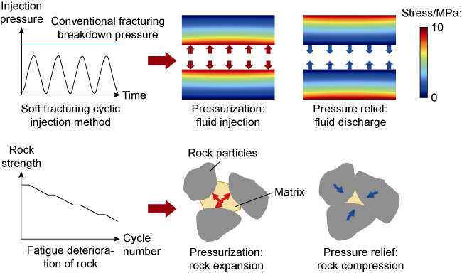
Fig. 1. Reservoir stimulation mechanism of soft hydraulic fracturing in HDR. |
1.2. Model assumption
The numerical model is based on the following fundamental assumptions:
(1) Pressure transmission within the rock matrix is continuous and isotropic, with consistent propagation speeds for both shear and compressional waves.
(2) Fracture propagation is considered quasi-static.
(3) The fracturing fluid does not chemically interact with the reservoir.
(4) The fracturing fluid is single-phase and remains in a liquid state at all times.
(5) Heat transfer in the temperature field occurs through convective and conduction, and local thermal equilibrium is maintained.
1.3. Governing equations
A soft hydraulic fracture propagation model was constructed using the finite element method, incorporating a cyclic loading function and rock strength deterioration constitutive relationship. COMSOL Multiphysics numerical simulation software was employed to numerically solve the fully coupled THM-FD model. This model simulates the initiation and propagation of fractures in a HDR reservoir under the coupling of four physical fields (temperature field, flow field, stress field, and rock damage).
1.3.1. Governing equations for the THM coupling model
The mass conservation equation for fluid flow within HDR under stress influence is given as follows [27]:
$ \rho_{\pi} S \frac{\partial p}{\partial t}-\nabla \cdot \frac{\rho_{\mathrm{m}} K_{\mathrm{r}}}{\mu_{\mathrm{f}}} \nabla p=-q_{\mathrm{m}}-\rho_{\circledast} \alpha_{\mathrm{B}} \frac{\partial \varepsilon_{\mathrm{vol}}}{\partial t}$
where $ S=\phi_{\mathrm{r}} \chi_{\mathrm{f}}+\left(\alpha_{\mathrm{B}}-\phi_{\mathrm{r}}\right) \frac{1-\alpha_{\mathrm{B}}}{K_{\mathrm{d}}}$
The energy conservation equation for heat transfer within HDR, considering both thermal convection and thermal conduction, is as follows [28]:
$ \begin{array}{c} {\left[\phi_{\mathrm{r}} \rho_{\varpi} C_{\varpi}+\left(1-\phi_{\mathrm{r}}\right) \rho_{\mathrm{r}} C_{\mathrm{r}}\right] \frac{\partial T}{\partial t}+\rho_{\varpi} C_{\varpi} u_{w} \nabla T-} \\ \nabla \cdot\left\{\left[\phi_{\mathrm{r}} \lambda_{\aleph}+\left(1-\phi_{\mathrm{r}}\right) \lambda_{\mathrm{r}}\right] \nabla T\right\}=W \end{array}$
The stress-strain equation, considering thermal stress and poroelastic effects, is as follows [29]:
$ G \nabla^{2} u_{i}+(\lambda+G) u_{j, j i}^{\prime \prime}-\alpha_{\mathrm{B}} p_{i}^{\prime}-\alpha_{T} K\left(T_{i}^{\prime}-T_{0, i}^{\prime}\right)+F_{i}=0$
1.3.2. HDR fracture criterion and fatigue damage evolution equations
The maximum tensile stress criterion and the Mohr- Coulomb criterion are used to define rock tensile damage and shear damage, respectively (Tension is positive, compression is negative). The equations are as follows [30]:
$ \left\{\begin{array}{l} F_{1}=\sigma_{1}-f_{40} \\ F_{2}=-\sigma_{3}+\sigma_{1}\left(\frac{1+\sin \theta}{1-\sin \theta}\right)-f_{c 0} \end{array}\right.$
When tensile damage occurs in the rock (F1≥0), the governing equation for the damage variable Ds is as follows [31]:
$ D_{\mathrm{s}}=\left\{\begin{array}{l} 0 \varepsilon<\varepsilon_{\mathrm{t} 0} \\ 1-\frac{f_{\mathrm{tr}}}{\varepsilon E_{0}} \quad \varepsilon_{\mathrm{t} 0} \leq \varepsilon<\varepsilon_{\mathrm{tu}} \\ 1 \varepsilon_{\mathrm{tu}} \leq \varepsilon \\ \mathcal{E}_{\mathrm{tu}}=\eta \mathcal{E}_{\mathrm{t} 0} \end{array}\right.$
where εtu=ηεt0
When shear damage occurs in the rock (F2≥0), the governing equation for the damage variable Ds is as follows:
$ D_{\mathrm{s}}=\left\{\begin{array}{l} 0 \varepsilon_{\mathrm{co}}<\varepsilon \\ 1+\frac{f_{\mathrm{cr}}}{\varepsilon E_{0}} \quad \varepsilon \leq \varepsilon_{\mathrm{co}} \end{array}\right.$
Traditional fracture propagation models only consider fracture extension under monotonic loading. However, in soft fracturing, cyclic loading reduces the mechanical properties of the rock, necessitating modifications to the constitutive relationships for fracture propagation under monotonic loads. This study incorporates fatigue damage into the brittle constitutive model to represent rock strength deterioration caused by cyclic loading.
The rock strength after n times of cyclic loading is as follows [32]:
$ \sigma_{0, n}=\left(1-D_{\mathrm{f}}\right) \sigma_{0}$
By incorporating the fatigue constitutive relationship of real HDR (granite in this study), the fatigue damage effects on rock under cyclic loading was simulated, quantitatively characterizing the deterioration of rock strength due to fatigue. The governing equation is as follows [33]:
$ \frac{\sigma_{\max }}{\sigma_{0}}=A \log _{10} N+B$
where, A and B are empirical parameters, which are sensitive to loading frequency, sample size, temperature, and rock saturation, and typically obtained through experimental data fitting. In this study, parameters A and B for granite were derived from fatigue testing, with values of -0.107 and 0.977, respectively [34].
Under a given load ratio (σmax/σ0), Eq. (8) is transformed to Eq. (9) to calculate the fatigue life N:
$ N=10^{\frac{\sigma_{\mathrm{mzx}} / \sigma_{0}-B}{A}} $
The fatigue damage for n cycles at the maximum applied stress σmax is given by [35]:
$ D_{\mathrm{f}}=\frac{\sigma_{0}-\sigma_{\mathrm{max}}}{\sigma_{0}} \frac{n}{N}$
Based on mesoscopic damage mechanics, rock suffers fatigue deterioration under cyclic loading, leading to a degradation in its mechanical properties post-damage. The governing equation for the elastic modulus during fracturing is as follows [36]:
$ E=E_{0}\left(1-\frac{n}{N}\right)\left(1-D_{\mathrm{f}}\right)$
$ \phi_{r}=\left(\phi_{r 0}-\phi_{r e}\right) \exp \left(-\alpha_{\phi} \sigma_{e f f}\right)+\phi_{r e}$
$ K_{r}=K_{0}\left(\frac{\phi_{\mathrm{r}}}{\phi_{\mathrm{r} 0}}\right)^{3} \exp \left(\alpha_{X} D_{\mathrm{f}}\right)$
2. Model validation
2.1. Validation of the soft hydraulic fracture propagation model
To verify the reliability of the numerical model in simulating fracture propagation, this study compares the simulation results with laboratory data from conventional hydraulic fracturing and soft hydraulic fracturing experiments. Using a true triaxial hydraulic fracturing experimental system (Fig. 2 ), conventional and soft hydraulic fracturing were conducted on cubic granite outcrop samples with side lengths of 0.1 m at room temperature (25 °C). The cyclic loading applied was set at 80% or 90% of the conventional continuous injection breakdown pressure (pb) (Fig. 3a ), with additional specific parameters provided in Table 1 .
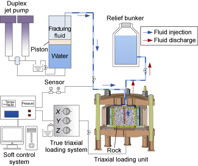
Fig. 2. True triaxial hydraulic fracturing experimental setup. |
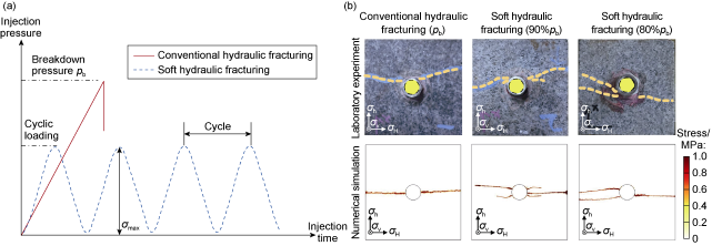
Fig. 3. Fluid injection methods (a) and comparison of fracture propagation results from laboratory experiment and numerical simulation (b) for conventional hydraulic fracturing and soft hydraulic fracturing. |
Table 1. Initial conditions and physical property parameters [39] |
| Item | Parameter | Symbol | Value |
|---|---|---|---|
| Initial conditions | Initial reservoir temperature | T0 | 200 °C |
| Pore pressure | p | 0.1 MPa | |
| Injection flow | qs | 0.02 kg/(m3·s) | |
| Frequency | f | 1 Hz | |
| Vertical in-situ stress | σv | 10 MPa | |
| Maximum horizontal principal stress | σH | 8 MPa | |
| Minimum horizontal principal stress | σh | 5 MPa | |
| HDR reservoir | Density | ρr | 2 650 kg/m3 |
| Compressive strength | fc0 | 200 MPa | |
| Tensile strength | ft0 | 10 MPa | |
| Initial elastic modulus | E0 | 60 GPa | |
| Poisson’s ratio | υ | 0.25 | |
| Thermal conductivity | λr | 3 W/(m·K) | |
| Isobaric heat capacity | Cr | 1 000 J/(kg·K) | |
| Porosity | ϕr | 1% | |
| Permeability | K0 | 1×10⁻¹⁸ m2 | |
| Thermal expansion coefficient | αT | 2×10⁻⁶ K−1 | |
| Injection fluid | Density | ρw | 1 000 kg/m3 |
| Thermal conductivity | λw | 0.5 W/(m·K) | |
| Isobaric heat capacity | Cw | 4 200 J/(kg·K) | |
| Viscosity | μf | 0.001 Pa·s |
A numerical model for soft hydraulic fracturing in HDR was developed based on laboratory experiments. The model was used to simulate the process of fracture initiation and propagation under vertical well conditions. The model is a 0.1 m × 0.1 × 0.1 m, with a central wellbore diameter of 0.016 m. In-situ stress is applied through external loading, with σH, σh, and σv set at 8, 5 and 10 MPa, respectively (Fig. 4a ). The outer boundary is set as a no-flow, insulated boundary, while the area surrounding the wellbore is designated as a pressure and thermal exchange boundary to simulate the effects of cyclic loading on rock strength fatigue deterioration and thermal stresses due to temperature differences during soft hydraulic fracturing of HDR. The simulation results are analyzed in the cross-sections along the directions of maximum and minimum horizontal principal stresses. During fracturing, the initial injection fluid temperature is set to 25 °C, with cyclic loading of 80%pb, 90%pb, and the maximum and minimum cyclic loads are controlled to ensure stable cyclic loading until the fractures propagate to the boundary. Initial conditions and physical property parameters are listed in Table 1.
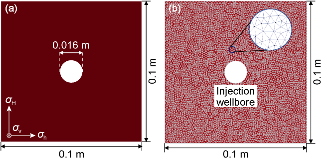
Fig. 4. Numerical model of soft hydraulic fracturing of HDR (a) and schematic diagram of finite element mesh (b). |
To determine the fracture initiation location and propagation direction, the finite element method is used to discretize and solve the mathematical model (Fig. 4b ). The coupled solution of the flow field, temperature field, stress field, and rock damage-fracture criterion are performed. The soft hydraulic fracture propagation model employs an unstructured mesh for spatial discretization, with an average element size of 0.5 mm (1/200 of the model’s characteristic length). The spatiotemporal evolution of pressure, temperature, stress, and damage is calculated using the implicit backward difference method.
2.2. Validation of soft hydraulic fracturing dynamic response model
Compared to conventional hydraulic fracturing, soft hydraulic fracturing uses cyclic injection of fracturing fluid, inducing a dynamic stress response within the reservoir. To further validate effectiveness of the model, the changes in radial stress, circumferential stress, and pore pressure at monitoring points (0.12 m from sidewall) over time under cyclic injection conditions (30-50 MPa) were simulated and analyzed. This approach verifies the dynamic response and numerical solution accuracy of the model. Fig. 5a to 5c illustrate the variations in radial stress, circumferential stress, and pore pressure over time (t=0-10 s) at the monitoring points. The numerical solutions are obtained through model calculations, while the analytical solutions are derived using the formulas for radial stress, circumferential stress, and pore pressure proposed by Senjuntichai et al. [40], which are based on Biot’s poroelastic dynamic equations in the Laplace transform domain. The close agreement between the numerical and analytical solutions confirms the accuracy of the numerical solution method of the model.
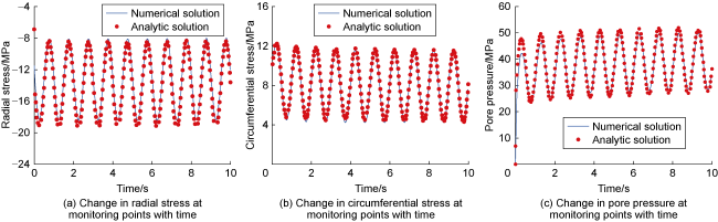
Fig. 5. Changes in radial stress, circumferential stress, and pore pressure with time. |
2.3. Validation of THM coupling model
By simulating the changes in soil column temperature, displacement, and pore pressure over time caused by thermally induced consolidation, the accuracy of the established THM coupling model was verified. Referring to the related research by Bai Bing [41], this study adopts the same model setup for thermal consolidation simulation. In this model, all boundaries are assumed to be adiabatic and closed, with roller-supported boundary constraints (i.e., no normal displacement) applied on all boundaries except the top surface. The setup involves applying a compressive load of 10 kPa to the top surface of soil column, setting a temperature difference of 50 °C, and imposing a pore pressure of 10 kPa. Fig. 6a to 6c show the variations in soil column temperature, displacement, and pore pressure at different times (1×10⁻¹ to 1×10⁵ s). The numerical solution is obtained through model calculations, while the analytical solution is derived using the THM coupling formula proposed by Bai et al. [42]. The results indicate that the numerical solutions are consistent with the analytical solutions, validating the accuracy of the THM coupling model and the numerical solution method established in this study.
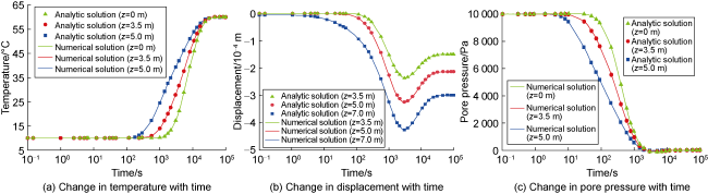
Fig. 6. Changes in soil column temperature, displacement, and pore pressure over time in the thermal consolidation model. |
3. Numerical simulation on fracture initiation and propagation in soft hydraulic fracturing of HDR
3.1. Fracture initiation and propagation characteristics
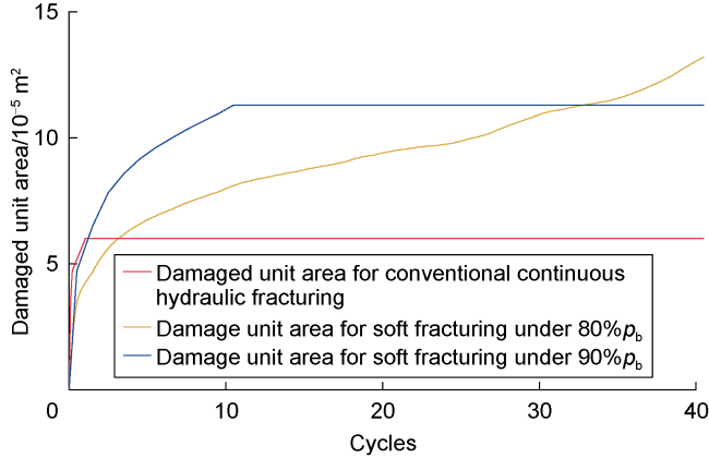
Fig. 7. Evolution of rock damage area with injection cycles. |
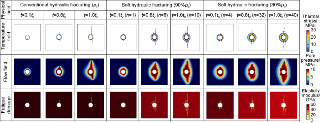
Fig. 8. Changes in temperature field, flow field, and fatigue damage over time in conventional and soft hydraulic fracturing. |
(1) At t=0.1t0, i.e. the initial stage of fracture propagation, temperature changes indicate that the injection of low-temperature fracturing fluid into the high-temperature reservoir induces thermal stress, particularly concentrated around the wellbore. This thermal stress causes the formation of numerous microfractures near the wellbore. As the fracturing time progresses to t=1.0t0, fractures extend into areas less influenced by thermal stress, and the in-situ stress field begins to dominate fracture propagation. The fractures then expand perpendicularly to the minimum horizontal principal stress. Additionally, due to the longer injection time in soft hydraulic fracturing than in conventional hydraulic fracturing, the injected fluid remains in contact with the high-temperature rock for a prolonged period, resulting in a broader influence range of thermal stress.
(2) From the fluid flow field distribution, we observe that at the early stage of fracturing, the fluid flow area appears circular. As fracturing continues, the injected fluid gradually penetrates further, increasing pore pressure and generating localized cracks within the rock. In the late stage of fracturing, the fractures expand along the direction of maximum horizontal stress, transforming the fluid flow area from a circular to an elliptical shape. The flow direction of the fluid then aligns with the fracture propagation direction.
(3) The fatigue damage distribution illustrates changes in the elastic modulus of the rock and fracture morphology throughout the fracturing process. For conventional hydraulic fracturing, the reduction in elastic modulus is localized around the fracture area, gradually decreasing as the rock undergoes damage, eventually reaching zero when the rock is completely fractured. In contrast, for soft hydraulic fracturing, the elastic modulus reduction occurs around the fractures and also shows an overall deterioration throughout the rock matrix. With prolonged injection time and repeated cyclic loading, the elastic modulus of the rock experiences a more widespread degradation, causing the rock to break at a lower pressure threshold. In summary, after prolonged fluid cycling, soft hydraulic fracturing induces fatigue damage in the rock due to the combined effects of fluid flow, pore pressure accumulation, and mechanical property degradation.
3.2. Pore pressure distribution and evolution
Soft hydraulic fracturing exhibits distinct pore pressure distribution and evolution patterns compared to conventional hydraulic fracturing. By recording the time-dependent pore pressure evolution at varying distances from the borehole (10, 15, 20, 25 and 30 mm) prior to fracture initiation, the spatial-temporal evolution and distribution characteristics of pore pressure within the rock were investigated. Under the injection temperature of 200 °C, the changes in pore pressure with time and distance from the borehole for both conventional and soft hydraulic fracturing are shown in Fig. 9. During the fracturing process, with increasing cycles of fluid injection, the fluid gradually permeates outward from the borehole, resulting in a steady rise in pore pressure. Additionally, the pore pressure decreases with increasing distance from the borehole center. Furthermore, factors such as horizontal in-situ stress differential and the permeability of the rock matrix also influence the distribution of the pore pressure field [20].
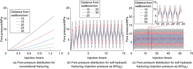
Fig. 9. Changes in pore pressure with time under different injection modes. |
In conventional hydraulic fracturing, the pore pressure at varying distances from the borehole increases monotonically with injection time (Fig. 9a ). Before fracture initiation, the pore pressure at any given time decreases as the distance from the borehole increases. However, in soft hydraulic fracturing, the pore pressure exhibits periodic increases and decreases corresponding to the cyclic injection of fracturing fluid, extending over a broader affected area (Fig. 9b -9c). Additionally, as the distance from the borehole increases, the periodic changes in pore pressure display a noticeable lag, meaning that the time to reach peak pore pressure varies with distance. This pressure fluctuation contributes to rock damage, facilitating fracture initiation and propagation.
3.3. Fracture propagation patterns and reconstructed stress field characteristics under the coupling of thermal stress and fatigue deterioration
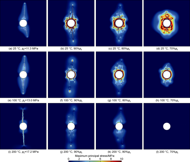
To clarify the fracture propagation patterns and reconstructed stress field characteristics under the coupling of thermal stress and fatigue deterioration, a comparative analysis was conducted on fracture patterns (Fig. 10 ) and stress field disturbance distributions (Fig. 11 ) under different fluid injection temperatures (25, 100 and 200 °C) for both continuous injection and cyclic loading conditions. For cyclic loading, three injection pressures were used, i.e. 90%, 80% and 70% of the breakdown pressure in continuous injection. In the case of conventional continuous injection, lower fluid injection temperatures led to reduced rock breakdown pressures, more complex fracture morphologies, and greater stress disturbances. For instance, at an injection temperature of 200 °C, only two double-wing fractures were generated along the direction of the maximum horizontal principal stress, with a limited stress disturbance range and a breakdown pressure of 17.2 MPa. Conversely, at an injection temperature of 25 °C, numerous microfractures emerged around the borehole, facilitating the rock fracturing. Sustained fluid injection then led to the formation of five hydraulic fractures extending in various directions. This resulted in a 34.30% reduction in breakdown pressure and a 45.41% increase in stimulated area.
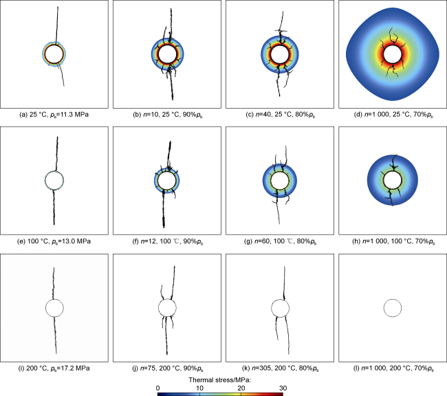
Fig. 10. Fracture morphology and thermal stress distribution under conventional and soft hydraulic fracturing of HDR at different temperatures and cyclic loads. Set 1 000 injection cycles as the injection limit. |
Fig. 11. Stress disturbance under conventional and soft hydraulic fracturing of HDR at different temperatures and cyclic loads. |
In the soft hydraulic fracturing process, as the injection cycles increase and the injected fluid temperature gradually decreases, more fractures and increasingly complex fracture morphologies appear. This occurs primarily because prolonged cyclic injection extends the interaction time between the cold fluid and the high-temperature rock, expanding the range affected by thermal stress, which promotes thermal fracturing. Additionally, multiple injection cycles induce fatigue deterioration in the rock, leading to deteriorated mechanical properties. This, in turn, lowers the breakdown pressure, facilitating the formation of a complex fracture network.
Analyzing the fracture morphology and stress field evolution under the coupling of thermal stress and fatigue deterioration reveals the following findings:
(1) When the injection temperature is 25 °C, the significant temperature difference between the low-temperature fracturing fluid and the high-temperature rock near the wellbore generates thermal stress, inducing thermal fracturing and intense stress disturbances (the red stress zone around the wellbore in Figs. 10 and 11 ). This promotes the initiation of numerous microfractures around the wellbore. At the cyclic load of 90%pb, hydraulic fractures reach the boundary after 10 injection cycles. Under the combined effects of thermal stress and fatigue deterioration near the borehole, multiple hydraulic fractures form in various directions. Compared to conventional hydraulic fracturing, the stimulated reservoir area increases by 88.33%. During fracture propagation, branching occurs, indicating that cyclic injection alters the fracture propagation pattern. At the cyclic load of 80%pb, more primary hydraulic fractures are generated, with greater tortuosity in branch fractures and longer extensions in all directions compared to the 90%pb case. The stimulated reservoir area increases by 16.81% relative to the 90%pb case and by 120% compared to conventional hydraulic fracturing. However, it takes 40 injection cycles for hydraulic fractures to reach the boundary, suggesting that lower cyclic injection pressure induces more twisted and complex fractures, which, however, may require longer injection durations. At an even lower cyclic load of 70%pb, hydraulic fractures fail to extend to the boundary even after 1 000 cycles, with only local fractures forming in multiple directions near the wellbore. This outcome arises because, at such low cyclic loads, the fluid pressure at locations farther from the wellbore remains insufficient. Even with extended cyclic loading that deteriorates the rock's mechanical properties due to fatigue, the fluid pressure cannot reach the minimum breakdown pressure of the rock, thereby preventing the formation of macroscopic hydraulic fractures. Zhuang et al. [21] corroborated this through laboratory experiments, which demonstrated that no macroscopic hydraulic fractures form when cyclic injection pressure falls below a certain threshold.
(2) When the injection temperature is 100 °C, the temperature difference decreases, which reduces the induced thermal stress, thereby diminishing the stress disturbance around the wellbore and reducing the number of microfractures caused by thermal damage (Fig. 10e -10h). Given the same cyclic load, the number of cycles required for hydraulic fractures to reach the boundary at 100 °C injection temperature is greater than that required at 25°C. Furthermore, as the cyclic load decreases, the required number of cycles increases exponentially. Compared to the injection temperature of 25 °C, fracturing at 100°C results in fewer hydraulic fractures, less tortuosity and simpler fracture morphologies. Under the conditions of 90%pb, 80%pb and 70%pb cyclic loads, the stimulated reservoir area decreases by 7.96%, 29.02% and 19.81%, respectively.
(3) When the injection temperature is 200 °C, where the fracturing fluid and rock are at the same temperature, thermal stress is eliminated, and only fatigue effect is present (Fig. 10i -10l). Under cyclic loads of 90%pb and 80%pb, the rock develops branched fractures and multiple primary fractures, contrasting with the double-wing fractures in conventional hydraulic fracturing. However, under the condition of 70%pb cyclic load, there is no macroscopic hydraulic fracture after 1 000 cycles of injection.
In summary, compared to conventional hydraulic fracturing, soft hydraulic fracturing reduces the breakdown pressure by 10%-30%. An increase in temperature difference enhances thermal stress, while a decrease in cyclic load expands the thermal stress-affected zone. When the injection temperature is 25 °C, soft hydraulic fracturing with cyclic loads of 90%pb and 80%pb increases the stimulated reservoir area by 88.33% and 120%, respectively, compared to conventional hydraulic fracturing. As the cyclic load decreases further, the reservoir stimulation efficiency diminishes. When the cyclic load drops to 70%pb, the fluid pressure far from the wellbore fails to reach the minimum breakdown pressure of the rock, making it difficult to generate macroscopic hydraulic fractures within a limited number of injection cycles (1 000).
4. Conclusions
Through prolonged cyclic injection, soft hydraulic fracturing forms a cyclically varying pore pressure field near the wellbore. Compared to conventional hydraulic fracturing, this process generates a broader sweep range, leading to fatigue deterioration in the mechanical properties of the rock, thereby allowing fractures to occur at lower pressures. As the distance from the wellbore increases, the cyclic variation in pore pressure exhibits a noticeable delay, creating pressure fluctuations that further facilitate rock damage.
Compared to conventional hydraulic fracturing, soft hydraulic fracturing reduces the breakdown pressure by 10%-30%. As the temperature difference increases, thermal stress intensifies. When cyclic loading decreases, the affected range of thermal stress expands. At an injection temperature of 25 °C, the stimulated reservoir area of soft hydraulic fracturing with cyclic loads of 90%pb and 80%pb improves by 88.33% and 120%, respectively, compared to conventional hydraulic fracturing. However, as the cyclic load further decreases, the effectiveness of reservoir stimulation diminishes. When the cyclic load decreases to 70%pb, the fluid pressure far from the wellbore cannot reach the minimum breakdown pressure of the rock, making the formation of macroscopic hydraulic fractures challenging within a limited number of injection cycles (1 000).
Nomenclature
A, B—fatigue parameter, dimensionless;
Cr—the specific heat capacity of the rock, J/(kg·K);
Cw—the specific heat capacity of the fluid, J/(kg·K);
Df—the fatigue damage parameter of rock after cyclic loading, dimensionless;
Ds—the damage variable that characterizes the complete failure of rock units during hydraulic fracturing, dimensionless, Ds=0 means that the rock is not damaged, while Ds=1 means that the rock is completely broken;
E—elastic modulus, Pa;
E0—initial elastic modulus of rock, Pa;
f—frequency, Hz;
fcr—residual compressive strength of rock, Pa;
fc0—uniaxial compressive strength of rock, Pa;
ftr—residual tensile strength of rock, Pa;
ft0—uniaxial tensile strength of rock, Pa;
Fi—the volume force in the i direction, Pa/m;
F1, F2—stress state functions, Pa;
G—shear modulus, Pa;
i, j—direction of rectangular coordinate system (x, y, z), m;
K—bulk modulus, Pa;
K0—initial permeability, m2;
Kd—volume modulus of drainage, Pa;
Kr—rock permeability, m2;
n—number of cycles loaded;
N—maximum number of cycles loaded (i.e. fatigue life);
p—pore pressure, Pa;
pb—breakdown pressure in conventional hydraulic fracturing, MPa;
$ p_{i}^{\prime}$—partial derivative of pressure with respect to space coordinates, Pa/m;
qs—injection flow, 0.02 kg/(m3·s);
qm—source/sink term, kg/(m3·s);
S—storage coefficient, Pa−1;
t—time, s;
t0—time consumed in the whole fracturing process, s;
T'—real-time temperature, K;
$ T_{i}^{\prime}$—partial derivative of temperature with respect to space coordinates, K/m;
Tin—injection temperature, °C;
T0—initial temperature, K;
$ T_{0, i}{ }^{\prime}$—partial derivative of initial temperature with respect to space coordinates, K/m;
u—rock displacement, m;
ui—the component of rock displacement in the i direction, m;
$ u_{i, j i}{ }^{\prime \prime}$—the second partial derivative of the displacement, m−1;
vw—fluid velocity, m/s;
W—heat exchange between cold fluid and hot rock, W/m3;
X, Y, Z—three directions of true triaxial experiment;
αB—Biot’s coefficient, dimensionless;
αK—permeability change coefficient of rock after damage, which is 5 in this study [38];
αT—coefficient of thermal expansion, K−1;
α—porosity influence coefficient, Pa−1, which is 5×10⁻⁸ in this study[33];
ε—strain, dimensionless;
εc0—maximum compressive principal strain corresponding to shear damage, dimensionless;
εt0—maximum principal tensile strain at element damage initiation, dimensionless;
εtu—ultimate tensile strain of the rock, dimensionless;
εvol—volume strain, dimensionless;
η—ultimate strain coefficient, dimensionless;
θ—angle of internal friction of rock, (°);
λ—Lame constant, Pa;
λr—thermal conductivity of rock, W/(m·K);
λw—fluid thermal conductivity, W/(m·K);
μf—injected fluid viscosity, Pa·s;
ν—Poisson's ratio, dimensionless;
ρr—rock density, kg/m3;
ρw—injected fluid density, kg/m3;
σeff—mean effective stress, Pa;
σh—minimum horizontal principal stress, MPa;
σH—maximum horizontal principal stress, MPa;
σmax—maximum stress in loading cycle, Pa;
σv—vertical in-situ stress, MPa;
σ0—initial strength of rock, Pa;
σ0,n—rock strength after n cycles, Pa;
σ1—maximum principal stress, Pa;
σ3—minimum principal stress, Pa;
χf—compressibility of fluid, Pa−1;
ϕr—rock porosity, %;
ϕre—residual porosity, %;
ϕr0—initial porosity, %.