

Introduction
China possesses abundant unconventional oil and gas resources [1-6], which constitute a critical strategic guarantee and alternative field for increasing hydrocarbon reserves and augmenting hydrocarbon production [7-9]. Horizontal well fracturing is a key technology for producing these resources [10-12]. The horizontal well fracturing technology of China has primarily drawn from the experience of North America, with ongoing upgrades. Unconventional reservoirs in North America, predominated by the deposits of passive continental margin basins, feature the simple platform structure, stable sedimentation model, widely-distributed high-quality source rocks, and high reservoir homogeneity [13-15]. The currently extensively-applied multi-stage and multi-cluster fracturing in long horizontal wellbores ensures robust uniform propagation capability of hydraulic fractures, realizing high reserve control degree [16-22]. However, the lacustrine shale oil and marine shale gas reservoirs of China are highly complex in structure [23-25], with segmentation by multiple sags and well-developed microstructures, faults, fractures and beddings. This leads to strong planar heterogeneity [26-29]. The multi-stage and multi-cluster fracturing approach often fails in creating balanced fractures by conventional hydraulic fracturing. Fracture length, height, and coverage are limited, and fracture-controlled reserves of wells are insufficient for delivering economically viable estimated ultimate recovery (EUR) of wells [30-31]. Recent advances in fracturing monitoring techniques like fiber optics and downhole camera monitoring have enhanced our understanding of fracture morphology and proppant distribution in stimulated reservoirs [32-35]. It has been found that 30% of perforation clusters exhibit non-uniform fracture propagation. Effective propped fracture lengths are 40-80 m, and heights are 10-25 m, which significantly restricts fracture coverage and reserve mobilization degree [36-40]. Overall, when applying the multi-stage and multi-cluster fracturing technology of North America to China, the fracture initiation energy is dispersed, leading to high difficulties in uniform fracture propagation and height extension. This results in low reserve utilization, single-well recovery factor and single-well EUR, indicating poor adaptability of this technology to the unconventional reservoirs of China such as continental shale oil and marine shale gas. Thus, innovative solutions are needed to develop a reservoir stimulation technology system tailored to China’s conditions.
This paper proposes the concept of “energy-focused fracturing”, and comprehensively examines the technological connotation, theoretical models, and core methods. The study clarifies the implementation path of energy-focused fracturing and confirms its effectiveness through field trials.
1. Connotation of energy-focused fracturing
The EUR of a horizontal well in an unconventional reservoir after multi-stage multi-cluster fracturing can be calculated using the following formula:
Assuming that fracturing of a horizontal well creates N fractures, for Fracture (i) (where (2£i£N-1)), the reserves it controls are determined jointly by the spacing between Fractures (i-1) and (i), and between Fractures (i) and (i+1). The reserves controlled by the first fracture (i=1) are determined jointly by the spacing between the first and second fractures and the seepage distance of the first fracture. Similarly, the reserves controlled by Fracture (N) are determined jointly by the spacing between Fractures (N-1) and (N) and the seepage distance of Fracture (N). Assuming that the spacing between two adjacent fractures is equally controlled by each fracture, the total reserves controlled by the well are the sum of the reserves controlled by all individual fractures:
Under normal production and engineering conditions, the adjustment range for F, Ee, and Ep in Eq. (1) is limited. To boost the EUR, one can increase the reserves controlled by a single well (V). As shown in Eq. (2), significantly increasing the length and height of hydraulic fractures is the engineering approach to enhancing the reserves controlled by a single well. Energy-focused fracturing creates laterally and vertically far-extending fractures in sweet spots with a high unit reserve factor qi (which represents the geological reserves per unit volume of the hydrocarbon reservoir), thereby substantially increasing the controlled reserves.
Energy-focused fracturing is a new concept for oil and gas reservoir development, characterized by “well controlled reserve as the core, focused fracturing as the means, and efficient development as the goal”. For strongly heterogeneous reservoirs, detailed reservoir evaluation along the entire horizontal section is conducted to identify favorable zones for reservoir stimulation. Through a geology-engineering integrated approach, well deployment, well trajectory, perforating methods, and fracturing parameters are optimized. Measures such as concentrated perforating and high-pump rate fracturing are employed to focus the limited fracturing energy on favorable zones, enabling large-scale and efficient reservoir stimulation. This process creates long and tall fractures and simultaneously extends secondary fractures from the main fracture to both sides, continuously connecting and activating natural fractures. This expands the fracture zone width and forms a network of superimposed and coupled hydraulic and natural fractures, doubling the fracture network volume and conductivity. Consequently, the control and mobilization of reserves by hydraulic fractures are maximized. As shown in Fig. 1, compared to the conventional multi-stage multi-cluster fracturing technology used in unconventional oil and gas development, energy-focused fracturing achieves a longer main fracture and a wider fracture zone in each fracturing stage. This allows for greater reserves control range at a lower cost.
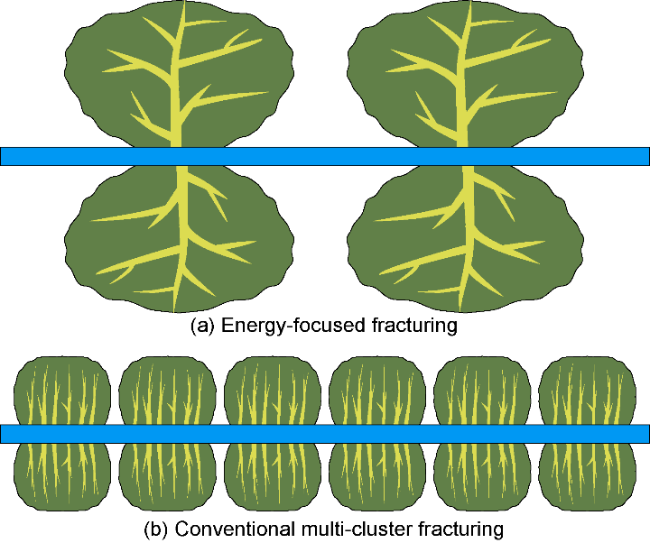
Fig. 1. Comparison of fracture morphology and controlled reservoir area between energy-focused fracturing and conventional multi-stage multi-cluster fracturing. |
2. Theoretical models for energy-focused fracturing
The key to implementing energy-focused fracturing lies in optimizing hydraulic fractures to match reservoir characteristics. Based on fracture attribute changes, the implementation of energy-focused fracturing is divided into three stages: high-velocity injection for rock breaking down and fracture initiation, formation and rapid propagation of the main fracture, and pressure diffusion to increase the stimulated reservoir volume. Corresponding theoretical models are established for each stage to guide subsequent technological optimization.
2.1. High-velocity injection for rock breaking down and fracture initiation
Energy-focused fracturing uses a single-cluster few- perforations mode, concentrating perforations in a short section. This focuses hydraulic fracturing energy for rapid rock breaking down and subsequent rapid deep fracture propagation. In contrast, conventional multi-cluster perforation has multiple perforation fracture initiation points. During fracturing fluid injection, these points fracture simultaneously, dispersing fracturing energy, slowing the fracture initiation rate of each fracture, and limiting fracture extent. In the focused fracturing mode, energy concentrates in one fracture cluster in the process of fluid injection and rock breaking. The energy is so focused that near-wellbore fluid exits the perforations at high speed, causing “rapid pressurization” at the perforations and “targeted breakthrough and rapid fracturing”. During the initial rock breaking stage, a 3D discrete lattice method is used to create a bonded particle model, which simulates fluid flow between elements, capturing the nonlinear features of fractures and joints during energy-focused fracturing, such as their opening, closing, and sliding. The lattice consists of a quasi-random 3D array of nodes with mass connected by springs. Nodes with mass represent particles, and springs represent contacts between them. The central difference formula for each node’s motion is expressed as follows:
The variation in the normal stress and tangential stress of the springs is calculated through the relative displacement of the nodes:
When FN exceeds the tensile strength or FS exceeds the shear strength, the springs fail, either in tension or shear, generating micro-cracks.
2.2. Formation and rapid propagation of main fractures
After the rock breaking down by energy-focused fracturing, the continued energy release enables fracture propagation. By reducing the number of fractures expanding simultaneously, the fracturing fluid is injected into an individual fracture at a larger rate, to make the fracture longer and taller. A 3D hydraulic fracture model with discrete displacement and propagation is established, considering four physical processes: rock deformation, proppant carrying fluid flow, proppant transport, and fracture propagation during the main fracture formation and propagation phase. The displacement discontinuity method is used to solve it, and the stress on the fracture surface is expressed with fracture displacement.
When multiple perforation cluster fractures propagate within a single fracturing stage, the fluid intake of each cluster is in dynamic balance, satisfying both the flow rate balance (see Eq. (8)) and pressure balance conditions (see Eq. (9)).
The perforation friction can be expressed as:
The fluid flow within each fracture can be represented as:
where δ is the Dirac function, which equals 1 when the position coincides with the injection point and 0 otherwise.
3D hydraulic fracture propagation follows the fracture toughness criterion: when the stress intensity factor (SIF) exceeds the fracture toughness, the hydraulic fracture grows. The SIF is calculated as follows:
$K_{\mathrm{L}}=\alpha \frac{\sqrt{\pi} E}{4\left(1-v^{2}\right) \sqrt{\Delta a}} W$
For a 1 m-square fracture element opened by 1 mm, the induced compressive stress at various points with different normal distances from it was calculated using the above formula, as shown in Fig. 2. It can be seen that if the cluster spacing is too small, strong stress interference occurs between multi-cluster fractures. Additionally, due to the diversion nature of multi-cluster fractures, the fluid volume per cluster decreases. These two factors lead to reduced fracture widths and SIF at fracture tips in multi-cluster fracturing, hindering fracture length expansion. Conversely, in the mode of energy-focused fracturing with single or few clusters per stage, large cluster spacing helps increase fracture length and enhance single-well control volume.
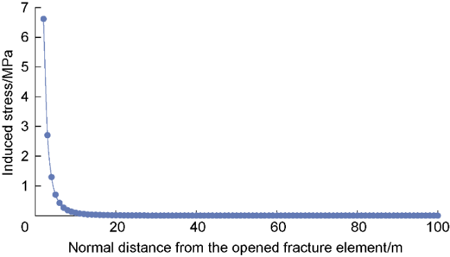
Fig. 2. Variation of induced compressive stress due to fracture element opening with respect to the normal distance from the opened fracture element. |
2.3. Pressure diffusion to increase stimulated reservoir volume
After fracturing, the instantaneous shut-in pressure at the well bottom is much higher than the formation pressure. Under high pressure, fracturing fluid continues to lose, hydrate, and break the rock, increasing the stimulated reservoir volume. By controlling the flowback scheme to keep the net pressure within fractures above the opening pressures of shale weak bond planes, coal cleat planes, and natural fractures for an extended period, new micro-fractures can be continuously opened, forming a more complex micro-fracture network. This further increases the length, width, and height of the hydraulic fracture extension, thus enlarging the stimulated reservoir volume and effective drainage area. According to elastic mechanics theory, when the net pressure within fractures meets the condition shown in Eq. (13), hydraulic fractures can propagate along weak bond planes, cleat planes, and natural fracture tips, forming a complex micro-fracture network.
Eq. (13) implies that the more pervasive the natural fracture system, the smaller the maximum and minimum horizontal principal stress difference, and the easier it is to generate a complex fracture network system and a wider fracture zone. In coal-bearing reservoirs, the presence of butt cleats, face cleats and large-scale fracture systems complicates the hydraulic fracture system further. By first creating long primary fractures through energy-focused fracturing and then increasing the net pressure within fractures to connect a wider natural fracture system, the stimulation attains the objectives of “longer, taller and wider” hydraulic fracture network.
3. Energy-focused fracturing technical system for development
Make full use of seismic, logging, and production data to build a geology-engineering integrated numerical simulation platform. This helps accurately describe the structures, faults, natural fractures, and stress state, and clarify the geological and engineering aspects of reservoir stimulation. By means of fracture monitoring and comprehensive evaluation, we can understand post-fracturing fracture length and proppant distribution. This ensures rational well placement, well type design, and well pattern planning, reducing “blind zone” areas. It also improves well-controlled and fracture-controlled reserves, boosting reserve recovery factor. For different reservoir types, we need to develop distinct technical approaches to create and efficiently use hydraulic fracture networks from energy-focused fracturing. In areas with slightly developed fractures, it is necessary to promote the main fractures to propagate vertically from the wellbore and extend laterally while creating long and high fractures. This connects more natural fractures, forming a coupled network of hydraulic and natural fractures, thus doubling the fracture network volume. In poorly fractured reservoirs, it is necessary to arrange proper hydraulic fractures and then create long and high fractures through fracturing, so as to achieve better control of fractures over reservoir depth. As shown in Fig. 3, on the basis of the commonly used platform-well group development model for unconventional oil and gas, by jointly optimizing factors such as the length and width of the fracture zone from energy-focused fracturing, as well as the spacing between horizontal wells and between fractures, we can achieve the optimal match between the hydraulic fracture network and horizontal well placement. In this way, efficient development through energy-focused fracturing can be realized.
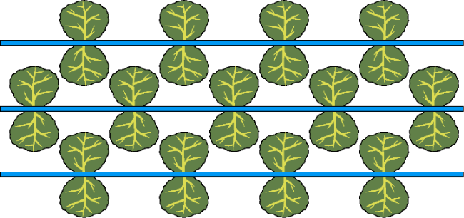
Fig. 3. Schematic diagram of well placement and fracture optimization for energy-focused fracturing development. |
3.1. Geology-engineering integrated design technology
The core of geology-engineering integrated design for energy-focused fracturing lies in characterization and optimization from seven aspects: structural characteristics, reservoir characteristics, geomechanical properties, reserve distribution, well placement, fracture network control, and reserve mobilization. This ensures efficient hydraulic fracture control over reservoirs and reserves. Specifically, the construction of energy-focused fracturing development technology firstly needs to grasp the macroscopic regional structural features and clarify the distribution patterns of fault and fracture systems. Then, study the reservoir characteristics, including burial depth, thickness, spatial distribution, internal structure, mechanical properties, and factors affecting hydrocarbon enrichment. Establish quantitative indicators to evaluate and classify favorable zones, preliminarily carry out reservoir classification and evaluation, and identify and locate “sweet spots”. In combination with regional and local in-situ stress conditions, implement differentiated well placement and pattern design, and carry out targeted engineering optimization. Continuously refine geological understanding, upgrade technological processes, and optimize engineering parameters collaboratively. This supports maximizing well-controlled and fracture-controlled reserves and reserve recovery, as well as subsequent refracturing.
3.2. Perforation optimization design technology
Perforation optimization is critical for fracture initiation in energy-focused fracturing. It involves adjusting perforation locations based on formation changes and optimizing perforation length and direction with consideration of the influence of perforation on fracture initiation.
Perforation location selection typically uses logging data to evaluate completed well sections and determine the optimal perforation intervals, ensuring efficient reservoir stimulation and avoiding potential engineering/geological risks. For vertical/directional wells with rich logging data, the selection focuses on: (1) acoustic amplitude logs to assess full-hole cementing quality and locate casing couplings, avoiding poor cementing sections and casing couplings; (2) logs like gamma ray, acoustic travel time, compensated neutron, and density to identify target reservoirs and evaluate their physical properties, and assess natural fracture development and structure integrity in the reservoirs via resistivity logs; (3) fluid property analysis and water layer identification using NMR logs to evaluate proportions of irreducible water and movable fluids and resistivity/SP logs to determine water saturation, avoiding high-water-cut zones and preventing water channeling from disturbing normal production; and (4) imaging, array acoustic, caliper, and dip logs to analyze in-situ stress states of each interval and mitigate risks like wellbore dislocation deformation and collapse. The goal is to select the intervals with good physical properties, high gas content, good fracability, convenient construction and low risk for perforating.
For horizontal wells, comprehensive logging data is often unavailable due to on-site limitations. In such cases, the drilling and mud logging data from itself and its adjacent wells in the same block must be integrated to evaluate and select optimal perforation locations. For a coal-rock gas horizontal well as an example, the following procedures are taken. First, conduct detailed reservoir correlation with adjacent wells to clarify local spatial variation of coal seam structure and occurrence. Then, track the horizontal well trajectory to determine its vertical position in the coal seam at different depths. Next, use acoustic amplitude logging to assess full-hole cementing quality and casing coupling locations, avoiding poor-quality sections and casing couplings. Finally, analyze data such as gamma ray while logging, drilling, gas logging, cuttings and element logging to pinpoint semi-bright or bright coal zones with good structure, simple coal seam structure, developed cleats and fractures, and relatively high gas content as quality perforation intervals.
Perforation optimization aims to maximize fluid energy under certain displacement, enabling rapid fracture initiation and efficient propagation. Select perforation charges to minimize fracture pressure, align perforation direction with maximum principal stress, and optimize perforation density aiming at reservoir fracturing with minimum energy and long-distance proppant transport with maximum energy to enhance fracture initiation capacity and proppant transport distance, enabling the extensive communication of fractures laterally to form a fracture network system. Design the number, length and direction of perforations according to the orifice throttling theory to promote the fracture propagation along the bedding direction and the efficient support. The single-stage single-cluster perforation mode in energy-focused fracturing maintains horizontal wellbore integrity, facilitating subsequent reservoir refracturing.
Based on the high-speed jetting rock-breaking theory model, a 5 m×5 m×5 m DEM fracture initiation model was established. The model parameters were set as follows: under a normal stress state, the vertical, maximum horizontal, and minimum horizontal principal stresses were 41, 36, and 29 MPa, respectively. Perforation lengths were set at 0.5, 1.0, 2.0, and 3.0 m, with 16 holes/m. The fracturing fluid injection rate was 3×10⁻³ m3/min, lasting 3.5 minutes. Simulations of fracture initiation under single-stage conditions with 8, 16, 32, and 48 holes (Fig. 4) show that under the 8-hole single-stage mode, fractures quickly initiated perpendicular to the minimum horizontal principal stress and propagated perpendicular to the wellbore, and the rapid convergence of fractures from multiple perforations formed a single fracture. In contrast, under the 32- and 48-hole single-stage modes, significant stress interference and shadowing occurred between perforations. Dispersed perforation energy causes multiple fractures near the wellbore, making it hard to form a single main fracture. This results in extensive ineffective expansion and support near the wellbore. As the number of perforation holes increased, near-wellbore fractures became more complex, with energy dispersion preventing effective hydraulic fracture initiation and leading to energy waste. Thus, using an energy-focused fracturing single-stage few-hole mode ensures high single-hole flow rates. This allows the pumped fracturing fluid to jet at high speed through a few holes, avoiding excessive near-wellbore fracture complexity, reducing bending friction, and rapidly forming a single fracture near the wellbore. This is crucial for the formation of subsequent long fractures. Effective near-wellbore fracture initiation and rapid dominant fracture formation via perforation optimization is a key technical goal in the fracture initiation phase of energy-focused fracturing.
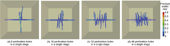
Fig. 4. Near-wellbore fracture initiation morphologies under different numbers of perforation holes. |
3.3. Energy-focused fracturing design
Energy-focused fracturing design encompasses fracture-propagation optimization, fracture-morphology control and long-distance proppant placement.
3.3.1. Fracture-propagation optimization
A fracturing software, FrSmart, independently developed based on the rapid-propagation model of main fractures, is used for fracture-growth simulation and optimization of the small-scale fractures from fracture initiation. Taking the Mizhi North Block in the Ordos Basin as an example, the geomechanical parameters are set according to the actual geological conditions to analyze the effect of cluster-number changes on the focusing effect under a fixed horizontal-section length (100 m) and injection volume (1 200 m3). In this case, the formation rock has a elasticity modulus of 5 985 MPa, a Poisson’s ratio of 0.35, and a normal-fault stress regime, with vertical, maximum horizontal, and minimum horizontal principal stresses of 41, 36, and 29 MPa, respectively, and a composite leak-off coefficient of 0.000 1 m/s0.5. The simulation shows that in a 100-m horizontal section, reducing perforation clusters from 8 to 1 can effectively avoid uneven fracture growth, increasing the maximum main- fracture length from 56 m to 366 m (Fig. 5). This indicates that the single-stage few-cluster energy-focused fracturing mode can concentrate the energy to enhance fracture length and height rapidly based on the formation of main fractures during the early fracture initiation.
Fig. 5. Comparison of fracture lengths under different numbers of fracturing clusters. |
3.3.2. Fracture-morphology control method
During fracture propagation, near-wellbore fracture net pressure is relatively high (8-10 MPa) in the early fracturing stage, mainly promoting fracture-length growth and main-fracture formation. In the late fracturing stage and areas far from the wellbore, the fracture-net pressure gradually drops (1-3 MPa), and fracture propagation mainly manifests as lateral growth to increase the stimulated reservoir volume. Thus, excessive fracture complexity or tortuosity near the wellbore can limit main-fracture propagation and proppant-transport distances. Simplifying and homogenizing near-wellbore fractures is essential for enhancing main-fracture growth and proppant delivery. By combining perforation optimization, construction-parameter optimization, active stress interference, and reverse proppant injection scheme, fracture-complexity control near the wellbore and fracture-length increase can be achieved. This enhances fracture height and sweep width, improving overall fracture complexity far from the wellbore.
As shown in Fig. 6, gas-content changes are compared between two horizontal wells using energy-focused fracturing and conventional multi-stage multi-cluster fracturing. In contrast to energy-focused fracturing, conventional multi-stage multi-cluster fracturing has relatively low fracture-net pressure. In the stage of high-speed jetting for rock breaking and fracture initiation and rapid propagation of main fracture, fracture-length growth is greatly restricted (only 50-80 m). In the pressure-diffusion to increase stimulated reservoir volume stage, fracture sweep width (6-11 m) and height growth (8-15 m) are also limited, resulting in a relatively small total simulated volume. Energy-focused fracturing enables rapid formation of long fractures under high net pressure in the early stage and promotes the lateral growth of fractures and increases the lateral sweep volume under low net pressure in the late stage. Simulation shows that compared to the single-stage 8-cluster mode, energy-focused fracturing increases the fracture-stimulated volume by 12%-18%.
Fig. 6. Comparison of gas content variation caused by fracture utilization between energy-focused fracturing and multi-cluster staged fracturing. |
3.3.3. Log-distance proppant transporting technology
Large-scale slick-water sand-transport experiments show that, under the energy-focused fracturing mode, reducing the number of perforation clusters and shots markedly increases the proppant-carrying fluid velocity at the perforation and inside the fracture. This mitigates excessive proppant settling and stacking at the fracture entry, keeps an open channel for the supporting fracture face, and allows proppant to be delivered continuously. When two fractures are eliminated, the net pressure in each remaining fracture rises by 12%-25%, fracture aperture increases by 1.5%-2.4%, and proppant transport distance improves by 8%-16%. By concentrating fracturing energy into fewer clusters, energy-focused fracturing greatly increases per-cluster and per-shot slurry rate, thereby boosting proppant kinetic energy and its reach within the hydraulic fracture. During fracturing implementation, an optimized “viscosity-rate-proppant” (V-Q-P) combination is applied to promote fine mesh proppant (150/75 μm (100/200 mesh)) to support narrow, far-end fractures, medium-mesh proppant (212/109 μm (70/140 mesh)) to support mid-section secondary fractures, and coarse-mesh proppant (830/380 μm (20/40 mesh)) to support wide, near-wellbore fractures. A fracturing-fluid system with rapid viscosity build-up, low leak-off and reduced friction is developed, and the combination mode of fluid viscosity with pump rate and proppant concentration during pumping process is adjusted, which promotes the match of fracturing fluid viscosity to proppant, achieving lateral long-reach support and vertical high- saturation placement—a “full-domain support” state.
3.4. Production control technology
Energy-focused fracturing generates a complex hydraulic fracture network system comprising both propped fractures and unpropped fractures, with the latter further categorized into hydraulic fractures and induced fractures. The induced fractures are distributed within the peripheral zones of hydraulic fracture networks, exhibiting fracture network volumes 1-2 orders of magnitude larger than propped and hydraulic fractures, while matrix permeability improves by 1-2 orders of magnitude. Due to the absence of proppants and their elastic strain state, these fractures demonstrate heightened stress sensitivity and gas-water relative permeability sensitivity. Inappropriate production management can readily damage the absolute permeability of the hydraulic fracture network and gas-water relative permeability, resulting in reduced pressure transient radius and the characteristics of high initial production followed by rapid decline. Regarding the characteristics of different types of unconventional reservoirs, different production engineering control technologies are established correspondingly. The production strategies after energy-focused fracturing must maintain the absolute permeability of fracture network while selecting tailored control strategies to establish a drainage-oriented production system with consideration of gas-water relative permeability characteristics across different production stages, so as to achieve efficient pressure depletion within the fracture network and optimal reserve recovery. Based on preliminary theoretical research and extensive field practice, we have developed engineered flow rate and pressure control theoretical curves for energy-focused fracturing production, as illustrated in Fig. 7.
Fig. 7. Engineering control curve for production and flow-back in energy-focused fracturing. |
In the flowback stage, hydraulic fracture network is dominated by single-phase flow with high fluid pressure and absolute permeability, so high drawdown pressure is favorable for rapid pressure propagation and efficient fracturing fluid flowback. However, the excessive flowback rate can make the proppant in the propped fractures flow back, resulting in reduced effective propped fracture network volume, rapid close of unpropped fractures under the effect of pressure sensitivity, insufficient flowback of fracturing fluid within far-end unpropped fractures, and a decrease in single well EUR. Therefore, above the target pressure, it is necessary to follow the principle of maintaining the absolute permeability of hydraulic fracture network for overall efficient pressure drop. When the formation pressure is higher than the target pressure, production shall be conducted at constant water rate to ensure uniform and efficient pressure transmission. When the formation pressure is close to the target pressure, production shall be conducted at constant pressure to ensure the pressure of the induced fractures at the end of fracture network to overall decrease to the target pressure. According to the fluids and their phase states in the stimulated reservoir, the target pressure is the pressure before the emergence of two-phase flow in the hydraulic fracture network. For the coal-rock gas reservoirs rich in free gas, the target pressure is the initial reservoir pressure; for the coalbed methane reservoirs dominated by adsorbed state, the target pressure is the regional theoretical desorption pressure.
In the production-enhancement phase, multi-phase flow dominates in the fracture network. Due to varying fluid viscosities and compressibilities, pressure-propagation speeds differ greatly across the network as two-phase saturation changes. During production, it’s key to analyze reservoir-fluid flow patterns, interpret pressure-propagation traits, and balance matrix gas supply with production rates to sustain the fracture network’s long-term conductivity. Also, it is necessary to adjust gas-water relative permeability as per two-phase flow features in the fracture network. This helps coordinate two-phase flow, slow low-viscosity fingering and water locking, and boost single-well EUR.
The pressure when two-phase flow capacities in the hydraulic fracture network are equal is the flow-equalization point. The pressure when two-phase permeability is equal is the permeability-equalization point. Based on gas-water relative-permeability traits, the production-enhancement process is divided into three phases. Before the flow-equalization point, the fracture network mainly has high-viscosity fluid flow with high saturation. But as pressure drops, low-viscosity methane saturation rises, and high-viscosity fluid flow capacity falls quickly. So, it is necessary to maintain a certain flow pressure reduction before the flow-equalization point, and leverage methane’s elastic drive for piston-like displacement in unsupported fractures at the network’s end and efficient depressurization in the matrix. After the flow-equalization point, both phases in the fracture network form continuous phases. As pressure drops further, adsorbed gas feeds in, keeping methane saturation high and enhancing flow capacity. However, methane’s high flow capacity means slow pressure propagation. Too-fast drawdown may raise gas saturation near the wellbore and narrow the pressure-drop funnel. Too-slow drawdown can increase reservoir gas saturation and decrease the flowback rate. Thus, in the stage dominated by free gas production after the flow-equalization point, focus on boosting high- viscosity fluid production and expanding the two-phase flow area until the permeability-equalization point is reached. After the permeability-equalization point, two- phase permeability reverses, and the fracture network is dominated by low-viscosity methane. As pressure drops more, gas-phase permeability index increases, decreasing the water-phase permeability. At this stage, free methane is produced efficiently, and adsorbed methane feeds in effectively, with the two-phase flow area stabilizing. To further enhance the flowback rate, control pressure to maintain stable production. The gas well enters a quasi- stable production phase with a fixed output. As pressure drops further, production shifts to a formation-energy- driven phase and a depressurization-desorption phase, and free and adsorbed gas are produced gradually. Due to the increasing Knudsen diffusion effect of matrix methane, methane diffusion and production slow down, causing a slight decline in gas-well output.
4. Field applications
4.1. Energy-focused fracturing in the Yangshuiwu buried-hill carbonate reservoir
The Yangshuiwu buried-hill carbonate reservoir in the Jizhong Depression of the Bohai Bay Basin lies 5 200-5 500 m deep, with low matrix porosity (2.2%-5.2%), low permeability ((0.1-0.3)×10-3 μm2), high temperature (150-170 °C), high elastic modulus (average 5.4×10⁴ MPa) and a large horizontal principal stress contrast (7.0-9.8 MPa). Natural fractures are mostly micro-fractures, highly filled and poorly connected. Vertically, reservoirs, tight layers and argillaceous carbonate layers are developed, with reservoirs and barriers being distributed in a layered pattern. Early development used dispersed perforation and commingled fracturing: perforation span 111-352 m, perforated thickness 34.4-44.0 m, 550-704 shots; yet post-frac rates were low with oil 4.3-7.2 t/d and gas (0.7-4.1)×104 m3/d, and production was unstable. Since 2019, energy-focused fracturing has been implemented. Perforation shifted from multi-layer, wide-span, continuous mode to sweet-spot-targeting intensive-perforating stimulation mode, greatly increasing fluid and proppant intensity per stimulation stage length. Compared with the non-energy-focused fracturing well Antan-X, the energy-focused fracturing well Antan-Y perforated an 8 m sweet zone (5 791.5-5 799.5 m) with fluid intensity rising by 12.5-fold. Simulation indicates fracture height remained within the reservoir and fracture length more than doubled (Fig. 8). Micro-seismic monitoring shows fracture zone length increased by 83%, greatly enlarging fracture length and stimulated reservoir volume.
Fig. 8. Comparison of fracture morphology and extension characteristics between two wells under different fracturing modes in Yangshuiwu buried hill carbonate reservoir. |
The long-term production results of the two wells are shown in Fig. 9. Well Antan-Y exhibits an oil productivity index of 0.41×10⁴ t/MPa and a gas productivity index of 0.17×10⁸ m3/MPa, versus Well Antan-X’s 0.28×10⁴ t/MPa and 0.11×10⁸ m3/MPa. Energy-focused fracturing has thus delivered remarkable performance, advancing exploration success and profitable production in the buried-hill play.
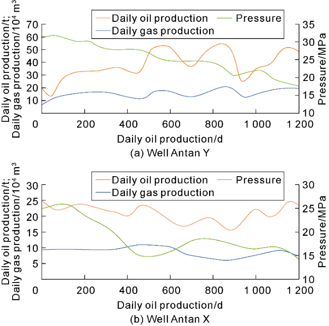
Fig. 9. Comparison of production performance between two wells under different fracturing modes in the Yangshuiwu buried hill carbonate reservoir. |
4.2. Field application of energy-focused fracturing in the Huabei CBM play
The southern Qinshui Basin is one of the first high-rank coalbed-methane (CBM) blocks in China to reach commercial development. The main 3# coal seam is at depth of 400-1 400 m and relatively uniform in thickness, averaging 7 m thick, with gas content of 7-33 m3/t. The coal has developed cleats, and exhibits low elastic modulus ((2.5-3.7)×104 GPa), high Poisson’s ratio (0.35), low tensile strength and strong heterogeneity. Due to the significant influence of tectonism, tectonic coal is developed. Early horizontal wells used the conventional multi-cluster, multi-stage scheme: 80 m stage spacing, 3 clusters per stage, 0.5-1.0 m perforated interval length, and pump rates of 12-16 m3/min; average daily gas output was 8 000-12 000 m3. After fine-scale evaluation of the entire horizontal section, premium targets were pinpointed, and energy-focused fracturing was carried out by increasing the stage spacing to 110 m and perforating intensively with a single cluster per stage over a 2 m interval. Fluid and proppant volumes fell sharply, yet pressures remained stable throughout, with no sand- blocking or over-pressure events. Key operational parameters for representative wells are listed in Table 1.
Table 1. Basic operational parameters for representative energy-focused fracturing (EFF) and non-EFF wells |
| Fracturing mode | Depth/ m | Gas content/ (m3·t-1) | Measured depth/m | Coal footage/ m | Stages/ clusters per stage | Avg. stage spacing/m | Perforated length/m | Shot density/ (holes·m-1) | Fluid per stage/m3 | Proppant per stage/ m3 | Pump rate/ (m3·min-1) |
|---|---|---|---|---|---|---|---|---|---|---|---|
| EFF | 1 030 | 21 | 2 346 | 900 | 9/1 | 110 | 2 | 16 | 1,100 | 60 | 10-14 |
| Non-EFF | 1 060 | 23 | 2 310 | 1 000 | 11/3 | 80 | 0.5 | 16 | 1,950 | 150 | 12-16 |
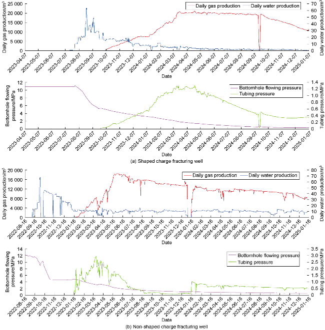
Production data of representative wells (Fig. 10) show a bottom-hole flowing pressure of 5.3 MPa for the energy-focused fracturing well versus 3.1 MPa for the non-EFF well, indicating better connectivity and lower flow resistance in the EFF case. Average peak-stable gas rate for the EFF well is 20 000 m3/d (sustained over 5 months) and 17 600 m3/d after one year, compared with 18 000 m3/d (sustained 1 month) and 12 500 m3/d, respectively, for the non-EFF well—evidence of larger controlled area higher reserves mobilization capacity and more stable and high gas supply of EFF well.
Fig. 10. Comparison of production performance of typical wells in Coalbed Methane reservoirs of Huabei Oilfield under different fracturing modes. |
After the large-scale application of energy-focused fracturing technology in CBM reservoirs in the Huabei Oilfield, it has driven a rapid increase in CBM production. The annual gas output surged from 11.85×10⁸ m3 in 2021 to 23.96×10⁸ m3 in 2024, representing an average annual growth rate of 25.5%.
4.3. Energy-focused fracturing pilot in Changqing coal-rock gas
In 2021, PetroChina achieved a breakthrough in the exploration and development of coal-rock gas in the Ordos Basin, and successfully developed CBM below the depth of 2 000 m, sparking the enthusiasm for the exploration and development of coal-rock gas again. Field practice, however, soon revealed high fracturing costs (1-2 times of that in shale), steep single-well production decline (40% in the first year), and low recovery rate of well controlled reserves (average 45.5%). There is an urgent need for technological upgrades to further improve the development efficiency of coal-rock gas.
The main seam in the Ordos Basin is the Benxi Formation 8#coal (Rₒ = 1.2-2.0 %, coking to lean coal). It is relatively stable in thickness (7-10 m), and has roof depth exceeding 2 500 m and average gas content of 21.8 m3/t. It is characterized by developed natural cleats and beddings (cleat density: 7-9 cleats/5 cm), low elastic modulus (less than 10×104 GPa), high Poisson’s ratio (0.3), low compressive strength (98 MPa, 43%-48% of other rocks), and low hardness (156 MPa, 6%-34% of other rocks). The regional horizontal principal stress contrast in the basin is only 2-5 MPa, playing a weak control over fracture direction, which is favorable for the formation of complex fracture networks. The “3-supers + 1-fast” (i.e., super high fluid volume, super high pumping rate, super high proppant volume, and fast flowback) limit volume fracturing was performed in the early period with the fluid intensity of 33 m3/m and proppant intensity of 6-7 t/m. The wide-field electromagnetic fracturing monitoring revealed an average fracture zone width of 99 m and half-length of 87-123 m (mean 100 m); a 1 000 m lateral produced at the rate of (10-12)×104 m3/d.
In May 2024, Well A in the Suide-Mizhi North block of the Ordos Basin was selected for an energy-focused fracturing pilot; the reservoir’s true vertical depth is 2 801 m, the horizontal section is 1 500 m long, the coal drilling ratio is 100%, and gas-show readings register a peak of 83.85% with an average of 45.22%. Using the optimization design technologies and methods described earlier, an EFF programme was finalized for this well. The entire well was treated in 10 stages/10 clusters with the primary cluster spacing of 100 m. The designed proppant intensity, fluid intensity and pump rate were 3.8 t/m, 20.2 m3/m, and 16 m3/min, respectively. The fracturing materials were composed of a proppant blend of 212/109 µm (70/140 mesh) quartz sand + 380/212 µm (40/70 mesh) quartz sand and a variable-viscosity slick-water system. Field execution was completed in August 2024 with total fracturing fluid injected 24 807.9 m3, total proppant 3 251.1 m3, and surface treating pressure 67-83 MPa; micro-seismic interpretation indicated fracture lengths of 148-233 m on the west wing and 153-194 m on the east wing, fracture widths 127-153 m, fracture heights 32-39 m, signifying a successful field trial. Post-frac test gas rate reached 10.47×10⁴ m3/d on a 15 mm choke. By January 1st, 2025, wellhead pressure was 17.1 MPa, daily gas rate 7.92×10⁴ m3, cumulative gas production 450.5×10⁴ m3, and flowback ratio 35.0%. Relative to earlier large-volume fractured horizontals, the energy-focused fracturing pilot well is lower in total fluid by 13%, total proppant by 21% and overall cost by 27.7%. Obviously, this technology offers a viable pathway for cost-effective and efficient coal-rock gas development.
5. Conclusions
Energy-focused fracturing raises fracture net pressure by optimizing cluster count, shot number and perforated length, thereby increasing primary-fracture length and height as well as branch-fracture sweep width. The resulting fracture network greatly enlarges well-controlled reserves and single-well EUR; large fracture area, short flow paths and high flow pressure gradients are achieved.
Energy-focused fracturing is realized through the geology-engineering integrated design, perforation optimization, fracturing processes design and production engineering control. Hydraulic fractures are transformed from “many, short and dense” to “few, long and sparse”, focusing energy to enlarge length, height and lateral sweep while extending proppant placement. Well controlled reserves and development effectiveness are thus enhanced.
Successful applications of EFF in the Yangshuiwu buried-hill carbonate reservoirs, shallow CBM and deep coal-rock gas demonstrate its significant efficacy. The technology promises broad applicability and will strongly drive high-quality development of low-permeability and unconventional hydrocarbon resources.
Nomenclature
Δa—length of the fracture-tip element, m;
Auu, Auv, Auw, Avu, Avv, Avw, Awu, Awv, Aww—elements of the sub-block stiffness matrix, describing the linear relationship between displacement discontinuities and induced stresses, Pa/m;
dp,k—orifice diameter of the k-th perforation cluster, m;
E—elasticity modulus, Pa;
Ee—success rate of engineering operations such as drilling and fracturing, %;
Ep—incremental production efficiency from later production schemes and EOR techniques, %;
EUR—estimated ultimate recovery per well, m3;
F—theoretical recovery factor per well under ideal conditions, %;
FN—normal stress, N;
FS—shear stress, N;
∑Fj(t)—resultant force in component j acting on a node at time t, N;
Hi—height of the i-th fracture, m;
i—fracture No.;
kN—normal stiffness of the spring, N/m;
kS—tangential stiffness of the spring, N/m;
Kd—orifice throttling coefficient, dimensionless;
KL—stress-intensity factor at the fracture tip, Pa•m0.5;
Ld,i—spacing between the i-th and (i + 1)-th fractures, m;
Lf,i—length of the i-th fracture, m;
m—mass of the discrete lattice, kg;
np,k—number of perforations in the k-th cluster;
N—total number of fractures;
pcf,k—along-hole friction from the k-th cluster to the heel-side end of the stage, Pa;
pnet—net pressure inside the fracture, MPa;
Δpnf—fluid pressure drop between the junction and the weak bond plane, cleat or natural-fracture tip, MPa;
po—bottom-hole pressure at the heel-side end of the stage, Pa;
ppf,k—orifice friction of the k-th perforation cluster, Pa;
pw,k—pressure in the first fracture element corresponding to the k-th cluster, Pa;
P—vector of fluid pressures within fracture elements, Pa;
q—fracturing-fluid flux per unit flow length, m2/s;
qi—unit-reservoir coefficient, dimensionless;
Qk—fracturing-fluid injection rate per unit fracture area for the k-th cluster, m/s;
QL—filtration (leak-off) velocity of fracturing fluid, m/s;
Qt—total injection rate of the fracturing stage, m3/s;
Ri—drainage radius of the i-th fracture, m;
t—time, s;
Δt—time step, s;
To—tensile strength of the rock, MPa;
uj(t)—displacement at a node in direction j (j = 1, 2, 3) at time t, m;
u—vector of horizontal shear-displacement discontinuities of fracture elements, m;
v—vector of vertical shear-displacement discontinuities of fracture elements, m;
vj(t)—velocity at a node in direction j (j = 1, 2, 3) at time t, m/s;
vN,j—normal velocity at a node in direction j (j = 1, 2, 3), m/s;
vS,j—tangential velocity at a node in direction j (j = 1, 2, 3), m/s;
V—well-controlled reserves, m3;
w—width of a fracture element, m;
w—vector of opening displacement discontinuities of fracture elements, m;
α—correction factor, dimensionless;
θ—angle between the hydraulic fracture and the natural fracture, (°);
ρs—density of the proppant carrying fluid, kg/m3;
σmax—maximum principal stress, MPa;
σmin—minimum principal stress, MPa;
σn—vector of in-situ stresses normal to the fracture element face, Pa;
υ—Poisson’s ratio, dimensionless.