

Introduction
Over the past 30 years, the natural gas industry of China has achieved remarkable breakthroughs, and successfully developed 11 representative giant gas fields including Yaha, Jingbian, Kela-2, Sebei, Deep Sea No.1, Yulin, Puguang, Sulige, Longwangmiao, Peiling and Keshen. At present, significant efforts are underway to advance the development technologies for deep coal-rock gas res-ervoirs. In the Ordos Basin, as the second-largest petroliferous basin of China, three types of large-scale gas fields have been built up, including the low-permeability carbonate gas field represented by the Jingbian gas field, the low-permeability sandstone gas field represented by the Yulin gas field, and the tight sandstone gas field represented by the Sulige gas field, which reveals the significant position of the Ordos Basin in the natural gas development of China [1]. The natural gas development of Ordos Basin began with the industrial gas flow obtained from the Shancan 1 well in 1989, marking the start of the development of the Jingbian gas field. By 2003, the annual output of the Changqing gas region reached 50×108 m3; by 2007, with the large-scale productivity construction in the Yulin and Zizhou gas fields, the annual output in the region exceeded 100×108 m3; and by 2013, driven by the rapid expansion of the Sulige gas field, the annual output of the whole region surpassed 300×108 m3. After nearly a decade of steady progress and continuous production improvement, the Sulige gas field achieved an annual production of 304.6×10⁸ m3 in 2022, cementing its position among the top ten largest gas fields in the world. This remarkable output propelled the annual production of the Changqing gas region to 506×108 m3, establishing it as the largest gas-producing region of PetroChina and positioning the Ordos Basin as the highest-yielding gas basin in China [2]. By 2024, the total natural gas production of the basin further climbed to 782×108 m3. Currently, the PetroChina Changqing Oilfield Company is intensifying efforts in the exploration and development of deep coal-rock gas, with a preliminary industrial scale already achieved in both reserves and production [3]. The Ordos Basin is undoubtedly the most practical and promising area to support continuous growth and large-scale, long-term stable production of natural gas in China.
Based on the current status of natural gas development in the Ordos Basin, this paper systematically analyzes the technical progress across key development stages, including large-scale benefit productivity construction, stable output and recovery enhancement, focusing on three typical types of gas reservoirs — low-permeability carbonate rocks, low-permeability sandstone, and tight sandstone, and summarizes three major development models. In addition, it reviews the technical advancements in deep coal-rock gas development, particularly in reservoir evaluation and sweet spot selection, well type and pattern optimization, and geosteering for horizontal wells. Considering the distinct development stages of the three main gas reservoir types and deep coal-rock gas, this paper further examines key challenges such as tapping potential in secondary pay zones, peripheral step-out and succession deployment, quantitative characterization and differentiated potential tapping of remaining gas, and development cost control. It also identifies future directions to effectively support the scientific development of various gas reservoirs in the Ordos Basin.
1. Development technologies and models for low-permeability carbonate gas reservoirs
The Lower Paleozoic gas reservoir in the Jingbian gas field is a typical example of low-permeability carbonate gas reservoirs. Under the control of dissolution, the reservoirs are characterized by generally developed erosion channels, exhibiting low porosity, low permeability, and strong heterogeneity [4-5]. The primary gas-bearing formation is the Ma51+2 section of the Ordovician Majiagou Formation, with the Ma513 layer serving as the primary gas-producing layer and Ma511, Ma512, Ma514, Ma521 and Ma522 as the secondary production layers. Since it’s discovered over 30 years ago, the Jingbian gas field has undergone two major development phases: the large-scale productivity construction and stable production stage, followed by the recovery enhancement stage. During the large-scale productivity construction and stable production stage, fine karst paleogeomorphology characterization technology and reservoir acid fracturing technology were developed, which effectively guided early scientific well deployment and supported long-term stable production of 50×108 m3 per year from the Lower Paleozoic reservoir. During the recovery enhancement stage, a combined development strategy integrating the potential tapping of primary production layer with the effective production of secondary production layer was established. This approach involved groove potential tapping within the Lower Paleozoic gas reservoir, rolling expansion in the peripheral area, vertical three-dimensional layer expansion to promote the utilization rate of main and secondary pay zones, and three-dimensional development of Upper Paleozoic gas reservoir + Lower Paleozoic gas reservoirs to extend the gas field’s stable production period. This ultimately led to the formation of a model for low-permeability carbonate gas reservoirs, centered on fine groove characterization and three-dimensional succession of Upper and Lower Paleozoic gas reservoirs.
1.1. Technologies for large-scale productivity construction and stable production
1.1.1. Fine karst paleogeomorphology characterization technology
During the long sedimentary and burial history, the Lower Paleozoic reservoir of the Jingbian gas field was continuously influenced by weathering leaching and fluvial erosion, resulting in the development of two secondary paleogeomorphological units: karst highlands and karst slopes. The karst highlands are mainly located in the western part of the reservoir, where vertical dissolution is dominant, and there is no stratified karst belt favorable for natural gas accumulation. The karst slopes are located in the central-eastern part of the reservoir, where erosion and dissolution are intense, giving rise to various tertiary geomorphological units such as residual hill, groove, pit and lowland. In the residual hills, main gas-producing layers are well preserved, and the stratified karst deposit is more developed, forming continuous vuggy reservoirs. The grooves, however, are lack of the main gas-producing layers and hosts few high-production wells. Due to the high hydrodynamic energy and intense karstification, however, high-quality reservoirs with developed dissolution pores are prone to form above both sides of these grooves. The distribution of grooves in the gas field is complex, with low seismic resolution and strong reservoir heterogeneity, leading to considerable variation in well productivity and challenges in well deployment. By integrating techniques such as paleogeological analysis, residual thickness, imprint, and layer flattening methods, the tertiary geomorphological units such as groove and pit can be identified. Further integration with pressure buildup tests, numerical simulations, and dynamic monitoring allows for a fine characterization of groove distribution. This framework reveals the reservoir distribution patterns and key control factors for high production, facilitating the selection of favorable areas for well locations such as residual hills and both sides of karst slopes. As a result, the proportion of high-yield wells increased from 20% to approximately 30%, with the average daily production of high-yield wells reaching 7.5×10⁴ m3 during the first five years, and the estimated ultimate recovery (EUR) per well projected at 3×10⁸ m3.
With the enrichment of data and the continuous advancement of research techniques, the characterization of the erosion-prone groove has become more refined, and the understanding of the groove distribution patterns has gradually evolved from initially "main groove extending along east to west" to "east-west branching continuous distribution", and ultimately to "coexistence of groove and pit" (Fig. 1). Based on the precise identification of tertiary geomorphological units, such as residual hill, groove, pit and valley, and considering the missing strata characteristics in the groove and pit, the strata distribution was finely characterized by sublayers. This led to a revised understanding of the distribution pattern of the Ma51+2 reservoir, revealing that the scale of groove was significantly smaller than previously recognized value, with the width shrinking from 2-3 km to 0.2-1.6 km. This revision increases the gas-bearing area of the main production layer by 500 km2 and adds nearly 300×108 m3 of recoverable geological reserves. An idea of well location arrangement for tapping the potential of remaining reserves in grooves was formed. Between 2021 and 2023, 35 wells were drilled in the grooves to tap residual reserves, increasing the utilization rate of the main production layer. The drilling success rate for Ma513 reached 88.5%, with an average gas layer thickness of 4.6 m for Ma51+2. The proportion of Class I and II wells was 94.3%, and the casing pressure during initial production was 18.6 MPa. In the first year, the average daily gas production per well was 2.5×10⁴ m3. With a deeper understanding of the groove distribution characteristics, the development of the Jingbian gas field has steadily progressed, providing strong support for the long-term stable production.
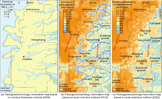
Fig. 1. Karst paleogeomorphology restoration of the Jingbian gas field. the relative paleogeomorphologic elevation is defined as the difference between the inter-marker maximum thickness of the drilling well and the thickness of the upper marker at other wells and unconformity plane. The upper marker is the top of the Taiyuan Formation, and the lower marker is the base of the Ma541 sublayer. |
1.1.2. Reservoir acid fracturing technology
The Lower Paleozoic reservoir in the Jingbian gas field is a low-permeability dolomite formation, posing significant development challenges. Acid fracturing has become a key technique for enhancing single-well productivity. For Class I and II reservoirs in the central part of the field, conventional acid fracturing and combination techniques using gelled acid and regular acid were initially adopted. By optimizing acid formulations (such as drag-reducing acid), the flow resistance of the acid was reduced and the etched fracture length was extended. The maximum acid volume per well reached 150 m3, and the average open-flow tested production increased to 17.31×10⁴ m3/d. For Class III reservoirs (tight dolomite), conventional acid fracturing was less effective. An innovative approach combining cross-linked acid and proppant-carrying fracturing was developed. This technique leverages both the dissolution capability of acid and the conductivity enhancement from proppant placement. The maximum sand volume reached 25.1 m3, the flowback rate exceeded 79%, and the absolute open flow rate increased to 37×104 m3/d. This effectively addressed challenges such as rapid fracture closure and insufficient conductivity. Through the integrated innovation of acid fracturing and proppant fracturing, the Jingbian gas field has developed a differentiated technical system tailored to various reservoir types, significantly enhancing the development performance of low-permeability carbonate gas reservoirs.
1.2. Techniques for gas recovery enhancement
After three decades of efficient development, the Jingbian gas field has entered its late stage of development. The primary strategy for enhancing gas recovery focuses on tapping residual gas in the main production layer and improving the utilization rate of secondary pay zones in Lower Paleozoic reservoir. Additionally, the three-dimensional development of the Upper and Lower Paleozoic reservoirs achieves the steady succession of tight gas in Upper Paleozoic, further extending the field’s stable production period.
1.2.1. Techniques for potential tapping of remaining gas in Lower Paleozoic main production layer
Based on gas production profile testing, dynamic reserve evaluation and drainage radius analysis were conducted by layers for gas wells. Results indicate that the well drainage radius in the main production layer is approximately 1.2 km, with the majority of gas produced from the central reservoir area, where the well pattern is basically matured with well spacing of 2-3 km. The remaining gas is primarily scattered between wells in the central area, along the edges of the grooves, and in zones with incomplete well area on the eastern and western sides. The central part of the reservoir features good physical properties and gas-bearing potential, with remaining reserves mainly classified as Class I + II. In contrast, the eastern side of the reservoir has poorer physical properties, with remaining reserves primarily belonging to Class III. The western side lies in a relatively low structural position, exhibits higher water saturation, and contains mostly Class IV reserves.
To assess the remaining reserves in the main production layer (Class I + II), a high-precision numerical reservoir model was established by integrating geological modeling and numerical simulation. The model quantitatively characterizes the distribution and amount of remaining gas, providing a clear deployment strategy such as horizontal expansion, infill drilling, and groove tapping to enhance the recovery. In Class III tight reservoirs in the Lower Paleozoic with low-productivity, marginal-economic, conventional acid fracturing treatment typically generates short acid-etched fractures, leading to suboptimal stimulation efficacy. However, the application of sand fracturing following acid fracturing has significantly improved stimulation outcomes. This combined stimulation strategy extends fracture lengths by 60% to 200% compared to acid fracturing while boosting well productivity by approximately 3.5-fold. For Class IV reserves in water-bearing zones, a phased well deployment strategy is adopted, progressing from east to west and from the outer margin inward, to improve the development well pattern. An "internal drainage and peripheral water control" strategy is implemented: peripheral wells are used to control production and slow down water encroachment, while central wells focus on enhanced drainage to reduce reservoir pressure, thereby improving the recovery of reserves in water-bearing areas.
1.2.2. Techniques for effective production of Lower Paleozoic secondary production layer
In the Jingbian gas field, the Lower Paleozoic secondary production layer holds 58% of the reserves but contributes only 15% of current production capacity. Effectively utilizing these reserves is critical for sustaining long-term stable production. The reservoir quality and gas well production capacity of karst-weathered carbonate gas reservoir are controlled by the development and filling degrees of secondary pores, vugs and fractures. Among these, fractured-vuggy reservoirs exhibit superior permeability and gas content compared to fractured-porous or porous reservoirs, making them the most favorable target reservoir. Therefore, the key to successful development of the secondary production layer lies in accurately identifying and targeting fractured-vuggy reservoirs. By integrating rock core descriptions, imaging logs, microscopic observations, porosity-permeability tests, and high-pressure mercury intrusion data, the log-based reservoir type identification standard and the reserve classification evaluation standard were established based on pore-vug-fracture relationships and forming mechanisms, the lower limit of production capacity of reservoir spaces was defined, and the distribution of the favorable areas of secondary production layer was characterized precisely. Applying this methodology, the reserves in the favorable areas of the Ma512 and Ma514 fractured-vuggy reservoirs were successfully determined. Based on reservoir distribution characteristics and drainage radius, well types and well patterns were optimized. Vertical or horizontal wells were deployed to economically unlock the potential of secondary production layer, thereby enhancing both recovery efficiency and the long-term production capacity of the gas field.
1.2.3. Techniques for three-dimensional co-development of Upper and Lower Paleozoic reservoirs
The Jingbian gas field features two distinct reservoir systems: the low-permeability carbonate reservoir in Lower Paleozoic and the tight sandstone reservoir in Upper Paleozoic. The main gas production layer of the Lower Paleozoic reservoir has a relatively mature and independent well pattern. In contrast, the Upper Paleozoic tight sandstone gas reservoir, the Class III reserves of the main production layer in Lower Paleozoic and the secondary gas production layer remain underdeveloped. By adopting a three-dimensional well pattern deployment strategy for integrated development of both the Upper and Lower Paleozoic reservoirs (Fig. 2), the single-well EUR is effectively improved, and thus the benefit development of reserves in the Upper-Lower Paleozoic, the secondary gas production layer, and the Class III areas of the primary gas production layer is achieved. Building upon refined characterization of Lower Paleozoic karst paleogeomorphology and effective sand body prediction in the Upper Paleozoic tight gas reservoir, the existing well site was systematically optimized to enable efficient three-dimensional development of Upper and Lower Paleozoic, where a set of well pattern is employed to exploit two reservoir systems synergistically (Fig. 2). Vertical wells are adopted in the well pattern of 500 m×650 m to develop the Upper Paleozoic gas reservoir, with a reasonable single-well control area of approximately 0.33 km2. For the Lower Paleozoic reservoir, vertical wells are employed in multilayer-developed areas with well spacing and row spacing of 1 000 m and 1 300 m, respectively (Fig. 2a); in favorable single-layer developed zones, horizontal wells are deployed with a spacing of 1 000 m (Fig. 2b). Through integrated three-dimensional development of Upper and Lower Paleozoic reservoirs, the Jingbian gas field has achieved the effective improvement of overall gas reservoir production degree, the effective succession of Upper and Lower Paleozoic gas reservoirs, and the extended stable production period.
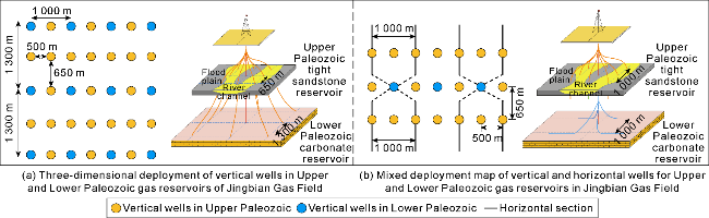
Fig. 2. Well pattern for three-dimensional development of Upper and Lower Paleozoic reservoirs. |
2. Development technologies and models for low-permeability sandstone gas reservoirs
The Yulin gas field is located in the northeastern part of the northern Shaanxi slope in the Ordos Basin, which is a typical representative of low-permeability sandstone gas reservoirs in China [1]. The gas field is divided into north and south parts. The southern Yulin South Self-operated Area is independently developed by Changqing Oil Field, and the northern Changbei Cooperation Area is jointly developed by CNPC and Royal Dutch Shell Group of Companies. The main development target is the Shan 2 Member of Shanxi Formation of Upper Paleozoic Permian, with additional gas-bearing intervals developed, including the Ma51+2 Member of Majiagou Formation of the Lower Paleozoic Ordovician, the Taiyuan Formation of Upper Paleozoic Carboniferous and the He 8 Member of Lower Shihezi Formation of Upper Paleozoic Permian. The Shan 2 Member reservoir is overall a downcutting valley-braided river delta sedimentary system, with delta plain and delta front subfacies developed. It is currently the only low-permeability gas reservoir in the Ordos Basin with natural productivity that does not require hydraulic fracturing stimulation. The reservoirs in the Changbei Cooperation Area belongs to the delta plain sedimentation, with better geological parameters such as gas layer thickness, porosity, permeability and gas saturation compared to those of Yulin South Self-operated Area. Based on the analysis of field geological survey, analogy, empirical formula and infill well pattern anatomy, the thickness, width and length of single sand body in the Shan 2 Member of Yulin gas field are determined to be 50-500, 1 000-2 500, and 1 000-3 500 m respectively. The width and length of the composite sand body are 2 500-4 000 m and 8 000-15 000 m, respectively. The composite sand body is mainly composed of four superimposed styles: multi-layer, multi-lateral, multi-layer multi-lateral and isolated. The high-quality reserves of Yulin gas field are mainly concentrated in the northern part of Yulin South Self-operated Area and the main sand belt in the central part of Changbei Cooperation Area (Fig. 3). The quality of reserves is relatively poor on both sides of Changbei Cooperation Area, and the southern part and east and west sides of Yulin South Self-operated Area due to the decrease of effective reservoir thickness or the influence of water cut. Since its production over 20 years ago, Yulin gas field has undergone two development stages: large-scale productivity construction and stable production, and enhanced recovery. It has formed a low-permeability sandstone gas reservoir development model with the overall deployment and pressure-depletion production of horizontal wells and the pressure control and stable production of vertical wells as the core, and the main production layer expansion, the potential tapping of the secondary gas production layer and the ground pressurization as the support, which supports the long-term stable production of Yulin gas field with an annual output of more than 50×108 m3.
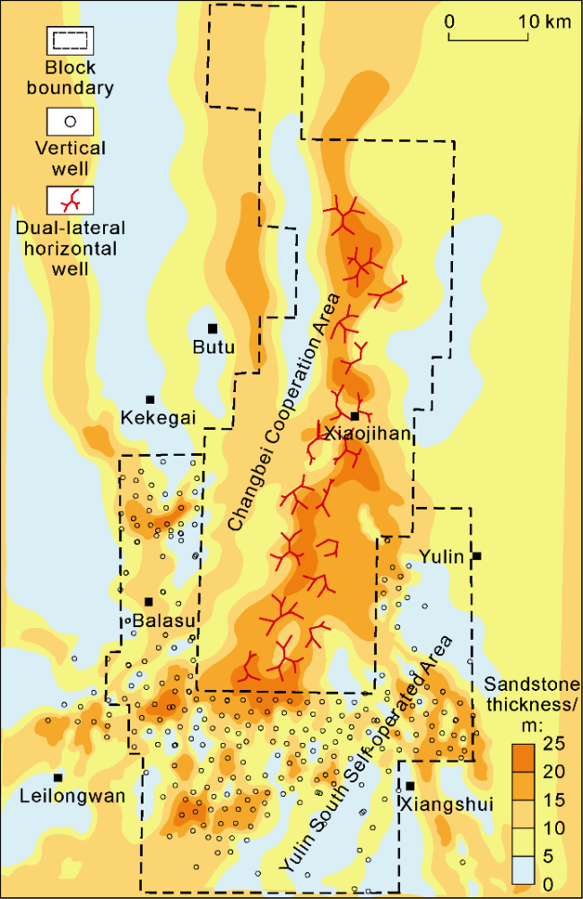
Fig. 3. Well pattern deployment map of Yulin gas field during large-scale productivity construction and stable production stage. |
2.1. Large-scale productivity construction and stable production technology
2.1.1. Vertical well pressure control and stable production technology
Considering the geological conditions of rapid lateral variation and strong heterogeneity of the reservoir in the Yulin South Self-operated Area, we adhered to the principle of "minimized investment, maximized output, and cost-effectiveness prioritization". The deployment of the well pattern is based on the principle of maximizing the discharge area and controlled reserves of gas wells. It is based on the square well pattern and adopts a non-uniform areal well pattern with a larger well spacing in the center of the main sand belt and a gradually smaller well spacing around it in the near north-south direction (Fig. 3). During the productivity construction period, 159 wells were built at one time for pressure-controlled production by vertical wells. The well spacing was 1.7-2.5 km, the average single well control area was 4.4 km2, the control reserves were 3.9×10⁸ m3, the average single well daily production was 3.5×10⁴ m3, and the annual scale production of 20×108 m3 was maintained for 15 years. This achievement realized the goal of high and stable production with few wells, supported the efficient development of Shan 2 gas reservoir in Yulin South Self-operated Area and formed the Yulin development model of Upper Paleozoic gas reservoirs.
2.1.2. Pressure-depletion production technology of dual-lateral horizontal well
The Changbei Cooperation Area has actively introduced advanced foreign technologies and adhered to the principle of maximizing economic benefits throughout the project lifecycle. A development technology based on "integrated reservoir characterization and 3D fine-scale modeling, lithological-structural seismic interpretation, precise trajectory guidance for dual-lateral horizontal well, and dynamic pressure-release production management" has been formed. The main sediment belt of the braided river was identified through the fine description of the reservoir, guiding the adoption of the dual-lateral horizontal well design for the expansion of the reservoir contact area. The horizontal well trajectory was preferentially deployed along the high-porosity and high-per-meability channel bar, to avoid the low-permeability flanks of the river channel (Fig. 3), and enhance the controlled reserves of each well. The staged fracturing technology is adopted to form a multi-level fracture network to improve the gas release efficiency. In the early stage of production, the formation pressure is gradually released through pressure control and drainage to avoid the reflux of proppant or sand production. The production pressure difference is adjusted through the wellhead throttle valve or intelligent control system to balance the formation energy. Subsequently, through dynamic pressure regulation and production allocation optimization, the comprehensive decline rate is reduced and the stable production period is prolonged. In general, under the development mode of clustered horizontal well pattern, low-well-density high-production systems, replacement from well to well, and dynamic production allocation optimization achieves an average single-well controlled area of 16 km2, with well controlled reserves exceeding 20×108 m3 and initial average daily production per well reaching 83×104 m3. The efficient utilization of Shan 2 gas reservoir is realized. It took only three years to build an annual production capacity of 30×108 m3 in the Changbei Cooperation Area, which was two years ahead of the development plan. This annual production scale was maintained steadily for 15 years. In this way, a model of the overall development of low-permeability sandstone gas reservoirs by horizontal wells is set up, which is awarded with the title of "Changbei Experience".
2.1.3. Comparison of the development methods between vertical and horizontal wells
The Yulin South Self-operated Area and the Changbei Cooperation Area are both located under the same braid river delta sedimentary system, but they have adopted two completely different development methods: vertical well pressure control and horizontal well pressure depletion. Through a detailed comparison in terms of gas reservoir development indicators and economic benefits, the specific differences between the two development methods can be demonstrated: (1) Comparison of average daily output per well and average EUR per well. The Changbei Cooperation Area has obvious advantages in both average daily output per well and average EUR per well in the first five years of a single well, reaching 40×104 m3 and 10×108 m3 respectively, while the Yulin South Self-operated Area has 4.8×10⁴ m3 and 2.6×10⁸ m3 respectively. (2) Comparison of gas production rate and recovery factor. Controlled by factors such as the well control area of horizontal and vertical wells, the number of deployed wells, and the overall control degree of block reserves, both areas are close in gas production rate and recovery rate. The two indicators in the Changbei Cooperation Area are 3.3% and 63.3% respectively, corresponding to 2.8% and 62.7% respectively in the Yulin South Self-operated Area. (3) Comparison of economic benefit. The internal rate of return is affected by multiple factors such as natural gas prices, gas well production, investment per well and operating costs. The EUR per well in Changbei Cooperation Area is 288% higher, the investment per well is 880% higher, and the unit operating cost is 25% higher than that in Yulin South Self-operated Area. Calculated based on this, its internal rate of return is 6.3 percentage points lower than that in Yulin South Self-Operated Area. Nevertheless, the internal rate of return of the Changbei Cooperation Area has also reached over 30%, which is at a high level of returns. It is demonstrated that whether from the perspective of gas field recovery factor or economic benefits, both the pressure relief by horizontal wells in Changbei and the pressure control by vertical wells in Yulin South have achieved efficient development of low-permeability gas reservoirs.
2.2. Enhanced oil and gas recovery technology
2.2.1. Technology for expanding the Shan 2 main gas production layer and tapping the remaining reserves
The low-permeability gas reservoir in the Shan 2 Member of the Yulin South Self-operated Area has maintained stable production naturally for 10 years. Since 2016, it has continued to maintain stable production by increasing the density between wells and periphery expansion to make up for the decline. The main reservoir of this gas reservoir has good connectivity. The initial one-time deployment of the well pattern has a high degree of control over the gas reservoir. The natural stable production effect of the gas wells is good, and the degree of reserve production is high. The undeveloped reserves are mainly distributed in the environmentally sensitive area on the east side of the gas field and scattered areas at the edge. Through the internal well pattern infilling and peripheral expansion, the potential of the relatively low-grade remaining gas was continuously tapped, and supported the Yulin South Self-operated Area to maintain a stable production of 18×108 m3 per year for seven years. The utilization rate of reserves in the Shan 2 Member of the Changbei Cooperative Area is relatively low. Under the development mode of well distribution along the middle of the gas reservoir in a concentrated cluster horizontal well group, a large amount of undeveloped proven reserves remain at the edge of the gas reservoir, which is the main target of potential tapping within the main gas production layer of Shan 2 Member. Through the deployment of vertical wells at expanded edges in the plane and infill wells to make up for the decline, the gas field recovery rate has been continuously improved.
2.2.2. Vertical secondary production layer potential tapping technology
To give full play to the role of the old gas field as a ballast stone, based on the resource foundation of the multi-layer gas reservoir and the fine gas reservoir description, the longitudinal expansion is utilized through the stratified deployment of secondary pay zones to make up for the decreasing production. The secondary pay zones developed in the Yulin Gas field mainly include the He 8 Member, Taiyuan Formation, and Ma51+2 sublayer, with submitted controlled reserves exceeding 700×108 m3, which are the main targets for longitudinal potential tapping. In view of the geological characteristics of thin and scattered sand bodies developed in the secondary production layers, based on the detailed description of the reservoir and fully drawing on the successful experience of developing multi-layer dispersed thin sand bodies with lens bodies in the Sulige gas field, the development methods of cluster vertical wells and S-shaped wells were mainly adopted, achieving the effective succession and utilization of multiple secondary production layers in the longitudinal direction, and further extending the stable production period of the gas field.
2.2.3. Multi-stage pressurized extraction technology
By 2024, the Shan 2 gas reservoir in the Yulin South Self-operated Area has achieved a reservoir utilization rate exceeding 95%. When the gas field enters the later stage of development, the pressure drops rapidly close to the pressure of the surface gathering and transportation system. Low-pressure natural gas is unable to enter the pipeline network, forcing some wells into intermittent production or shutdown. The number of low-yield wells and water-producing wells has increased, resulting in a serious decline in production capacity and economic benefits. At the same time, facing the pressure of stable production and supply guarantee, it is urgent to further reduce the abandonment pressure through pressurization technical measures, so as to realize the potential tapping of sporadic remaining gas and increase the recovery rate. Since 2020, the Yulin South Self-operated Area has gradually implemented multi-stage pressurization and production enhancement measures, mainly including two parts: multi-stage pressure regulation and dynamic optimization of production allocation. Firstly, according to the pressure changes in different development stages such as the stable production period and the decreasing period of the gas well, multi-stage pressurization nodes such as wellhead throttling, gas collection station pressurization, and regional compressor station are set up to gradually reduce the abandonment pressure at the wellhead. Secondly, through production dynamic analysis and numerical simulation, a reasonable production allocation plan is formulated to avoid the simultaneous decline of pressure and output caused by excessive initial production allocation.
To maximize the development potential of gas wells, numerical simulation methods are adopted to demonstrate the remaining workload of the first-stage pressurization and the production increase potential of the second-stage pressurization. Three aspects of fine research have been carried out: (1) Optimization of pressurization timing. The numerical simulation based optimization of the single well pressurization timing and the station pressurization timing is carried out with the gas gathering station as the unit to maximize the utilization efficiency of the formation energy. (2) Division of the pressurization unit. Based on the location of the gas collection stations and the distribution of pipeline network, regional pressurization is carried out by taking the gas collection stations with similar pressurization timing and adjacent geographical locations as units. (3) Preferred pressurization mode. Give full play to the gathering and transportation capacity of the existing pipeline network, without increasing the ground double-line pipeline network, gradually reduce the scale, lower the pressure and increase the pressure in steps to achieve the goal of reducing the production decline and increasing the recovery factor. Through reasonable pressurization, the stable production period of gas wells has been extended from the traditional 2-3 years to over 5 years. It is predicted that the ultimate incremental gas production will be 21×108 m3, and the recovery factor can increase by 2.2 percentage points. Simultaneously, it can significantly reduce the number of inefficient wells, and lower the frequency of well servicing. Multi-stage pressurization technology effectively supports extended stable production, enhanced recovery factor, and optimized economic efficiency for the Yulin South Self-operated Area, providing positive reference significance for gas fields in the later stage of development when dealing with such challenges.
3. Development technologies and models for tight sandstone gas reservoirs
Driven by technological and management innovations, PetroChina has successfully developed lenticular tight sandstone gas reservoirs represented by Sulige in the Ordos Basin. The Sulige gas field is located on the northwestern side of the Yishan Slope in the Ordos Basin, with the development intervals being the He 8 Member of the Lower Shihezi Formation and the Shan 1 Member of the Shanxi Formation of Permian [6-7]. It belongs to a continental braided river sedimentary system, where the effective reservoirs are mainly coarse sandstone facies deposited in the channel bar and river channel bottom. High-quality gas-bearing sand bodies form a "sand-in-sand" binary structure, embedded within matrix reservoirs as "lenticular" bodies [8]. The effective sand bodies are small in development scale, occur in a multi-layered isolated and dispersed state, have poor lateral continuity and connectivity, and exhibit large-area continuous distribution on the plane after multi-stage overlapping. Through comprehensive analysis using multiple methods such as field outcrop observation, geological dissection of dense well pattern, and interference well testing, it is determined that the main ranges of thickness, width, and length of single effective sand bodies in the gas field are 1-5 m, 200-500 m, and 400-700 m, respectively [9]. The overall average reserve abundance of the gas field is approximately 1.5×10⁸ m3/km2, showing significant planar differentiation characteristics: high-quality reserves are mainly concentrated in the central area of Sulige, while the reserves quality is poor in the eastern and southern areas due to tight reservoirs, and in the western area due to high water cut [6,10]. Since its discovery more than 20 years ago, the Sulige gas field has mainly gone through two development stages: large-scale benefit-based productivity construction, and stable production and enhanced recovery. A development model for tight sandstone gas reservoirs has been formed, with the core of improving single-well production and optimizing well patterns to enhance recovery, supported by technologies such as production system optimization, refracturing, old well sidetracking, drainage gas recovery and pressurized production. This model has supported the gas field's annual production to exceed 300×108 m3 and enter the ranks of the world's top ten gas fields.
3.1. Large-scale benefit-based productivity construction technology
Enrichment zone selection technology: Based on the establishment of a large-scale braided river sedimentary model and the background of large-area continuous distribution of multi-stage superimposed large braided river sand bodies, it is clarified that the coarse sandstone facies deposited in channel bar and river channel bottom have high quartz content and strong compaction resistance, which are conducive to the preservation of primary pores and the formation of secondary pores. These are the main controlling factors for the formation of effective reservoirs, with multiple achievements obtained as follows: (1) The geological characteristics of the gas field, including small-scale effective sand bodies, scattered distribution, poor connectivity and strong heterogeneity, are confirmed. Laterally, three distribution patterns can be divided: isolated type, channel bar-bottom cutting connection type, and channel bar lateral cutting and partial connection type. (2) Six types of lithofacies association models are established, and the sedimentary positions of different lithofacies associations in the braided river system are clarified. High-energy channel complexes are favorable areas for coarse lithofacies deposition, providing a scientific basis for the selection of enrichment areas and well locations. Accordingly, the area of selected Class I+II enrichment zones is 1.2×10⁴ km2 with reserves of 1.6×10¹² m3. Among them, the average gas layer thickness in Class I enrichment zone is 12 m, and that in Class Ⅱ enrichment zone is 8 m. (3) Through digital seismic and pre-stack multi-information gas-bearing detection technologies, the problem of gas layer identification under the complex condition of mixed distribution of mudstone, gas-bearing sandstone, strongly consolidated sandstone, and high-water-cut sandstone is solved, effectively improving the proportion of Class I+II wells and the gas layer encounter rate of horizontal wells.
Well type selection technology: A development mode dominated by vertical wells and supplemented by horizontal wells has been established for the geological conditions of multi-layer lenticular reservoirs [11-13]. Aiming at the characteristics of tight gas reservoirs, including small-scale effective sand bodies, scattered distribution, and multi-layer superposition, and combining with horizontal well development tests, the geological target selection criteria for horizontal well deployment have been established as follows: (1) Gentle structure, stable sand body distribution predicted by seismic reservoir technology, and good gas-bearing display in gas detection; (2) Braided river superposition zone with sand body thickness greater than 20 m; (3) Good reservoir continuity and strong correlation with adjacent wells; (4) Gas layer thickness greater than 6 m, with vertical reserve concentration of the main gas-producing layer exceeding 60%; (5) High production in adjacent wells and gas-water ratio less than 0.5 m3/104 m3; (6) When deploying infill wells in developed areas, high formation pressure should be ensured. The horizontal well target selection technology has played a critical role in improving the development effect of horizontal wells and ensuring the productivity construction pace of the gas field. As of the end of 2024, the number of horizontal wells put into production accounted for 11% of the total in the gas field, contributing more than 30% of the total production.
Well pattern optimization technology: During the early evaluation stage of the Sulige gas field, two sets of well patterns with well spacings of 800 m and 1 600 m were deployed in the pilot test area to analyze the number and scale of gas-bearing sand bodies encountered by gas wells. Among 28 gas-bearing sand bodies, 21 had widths less than 800 m, accounting for 75%. By integrating geological dissection, transient well testing, interference well testing, numerical simulation, and other methods, the well spacing and row spacing of the development well pattern were optimized to 600 m×1 200 m. Based on this, a 50×108 m3 development plan for the Sulige gas field was formulated, with a recovery factor of approximately 19%. During the subsequent productivity construction period, on the basis of the 800 m and 1 600 m well patterns, infill pilot tests were continuously carried out, forming a test well pattern of (400-600 m)×(600-800 m). It was demonstrated and determined that the basic development well pattern spacing and row spacing for the gas field were 600 m×800 m [9,14]. Development plans with annual productions of 100×108 m3 and 230×108 m3 were successively formulated, and the recovery factor was increased to over 30%.
Development index evaluation and development plan formulation technology: The strong heterogeneity of the reservoirs in the Sulige gas field leads to significant differences in single-well test production, with the production ratio between high-yield and low-yield wells exceeding 10. Gas wells are classified into three categories through the establishment of gas well classification criteria. Cluster analysis of 54 early evaluation wells determined the core index of the gas field, namely average single-well EUR as 2.248×10⁴ m3. Meanwhile, a development plan formulation technology was established for the first time, with the product of single-well production and the number of development wells as the core basis, guiding the formulation of development plans for different stages of the Sulige gas field. As of the end of 2024, the actual production performance of nearly 20 000 vertical wells put into production was basically consistent with the design indicators of the development plan, confirming the reliability of the plan formulation method and effectively supporting the large-scale benefit-based productivity construction and subsequent long-term stable production of the Sulige gas field.
Reservoir stimulation technology for single-well production enhancement: Constrained by the inherent "low porosity, low permeability, low pressure" properties of tight gas reservoirs, gas wells cannot produce industrial gas flow without reservoir stimulation. Aiming at the characteristics of the Sulige tight gas reservoir, including vertical multi-layer superposition, poor lateral connectivity, and the development of "flow barriers" within the reservoir, vertical multi-layer and horizontal multi-stage fracturing stimulation techniques are key to maximizing reservoir stimulation, improving the utilization rate of well-controlled reserve, and achieving beneficial development [15-18]. Through more than 20 years of research, fracturing in vertical wells has evolved from single-layer or commingled fracturing to separate layer fracturing with independently developed coiled tubing. The number of mechanical separate fracturing layers has increased from an initial 3 to over 7, accompanied by the independent R&D of stage fracturing technologies. In horizontal wells, fracturing has evolved from non-fracturable capacity to multi-stage multi-cluster volume stimulation, with the number of fracturing stages exceeding 10. The technologies of staged fracturing with bridge plug in cemented completion and temporary plugging multi-cluster fracturing within stages have been fully independently developed. The continuous iterative upgrading of reservoir stimulation technologies has significantly increased the single-well production of lenticular tight gas represented by the Sulige gas field.
3.2. Stable production and enhanced recovery technologies
Through preferential development of enrichment areas, the Sulige gas field established an annual production capacity of 249×108 m3 by the end of 2014, with an annual production reaching 230×108 m3, and entered the stable production stage since 2015. Unlike the production characteristics of conventional gas reservoirs, tight gas wells generally have no stable production period and require continuous commissioning of new wells to compensate for production decline and maintain long-term stable production of the gas field [19]: (1) Stable production is sustained through new block production capacity construction; (2) Well pattern infilling is carried out in developed enrichment areas to improve reserve utilization rate and recovery factor, achieving successive stable production. Given that most of the undeveloped blocks in the Sulige gas field have low reserve abundance or high movable water saturation, and the gas well production is generally lower than that of infill wells in enrichment areas, improving the recovery factor of enrichment areas has become a more economical technical means for stable production of the gas field, while undeveloped low-grade reserves serve as an important reserve for long-term stable production. A series of enhanced recovery technologies have been formed focusing on the dual objectives of economic benefits and recovery factor enhancement, with well pattern infilling technology as the core, supported by production system optimization, refracturing, old well sidetracking, drainage gas recovery and pressurized production.
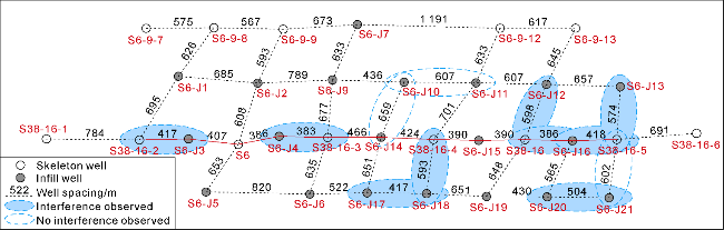
Well pattern infilling and optimization technology: For the Sulige tight gas reservoir characterized by extensive hydrocarbon generation, continuous hydrocarbon accumulation, large-area gas-bearing distribution, and scattered gas layer occurrence, the core of well pattern infilling lies in determining economically effective well pattern density based on accurate understanding of the development scale and distribution law of effective reservoirs and mastery of gas well production dynamic response characteristics. To this end, the principle of "overall effectiveness of gas field development, break-even of infill wells, and moderate inter-well interference" for well pattern infilling adjustment has been proposed. A multi- dimensional well pattern optimization technology integrating geology-reservoir-economics has been constructed, including quantitative geological modeling, dynamic drainage area method, production interference rate method, economic index evaluation and numerical simulation, to demonstrate the optimal well pattern density for different reservoir types. The goal is to accept a certain degree of inter-well interference under the premise of economic benefits, optimize the developing infill well pattern of the gas field as a whole, and significantly improve reserve utilization rate and recovery factor: (1) The core of the quantitative geological modeling is to determine the scale and distribution frequency of effective single sand bodies, and evaluate the sand body grade and reserve utilization rate effectively controlled by the current well pattern according to the main scale of effective single sand bodies [20]. (2) The dynamic drainage area method is based on the pressure and production data of gas wells reaching pseudo-steady state, and fits to determine important indicators such as gas well pressure relief range, dynamic reserves, and ultimate cumulative production by comprehensively considering parameters such as artificial fractures and reservoir physical properties. The reserve utilization rate under different well spacing and patterns is evaluated by analyzing the distribution frequency of gas well drainage areas. (3) The production interference rate method quantitatively characterizes the impact of well pattern infilling on the average production of gas wells in a certain area, evaluates the connectivity of reservoirs under different well spacing and patterns, and then determines the feasibility of well pattern infilling. (4) The economic index evaluation is oriented by development benefits, with internal rate of return as the core evaluation parameter. By establishing a multidisciplinary constraint evaluation model of well pattern density, single-well cumulative production, recovery factor, and economic benefits, it can determine the adjustment range of technical and economic well pattern density to guide well pattern infilling adjustment. (5) The numerical simulation establishes three-dimensional fine geological model and numerical simulation for production dynamic fitting to predict gas well production indicators under different reservoir quality conditions, and then determines the optimal well pattern density. Through gradual and detailed demonstration, it is determined that the well pattern density in the enrichment area of the Sulige gas field was changed from the basic skeleton well pattern of 600 m×800 m to 400 m×600 m (Fig. 4), and the recovery factor is increased from 32% to approximately 45%.
Fig. 4. Planar distribution map of infill well pattern and interference well test results in Su 6 Block. |
Enhanced recovery supporting technologies: Supporting technologies such as production system optimization, refracturing, old well sidetracking, drainage gas recovery, and pressurized production further improve recovery factor primarily by maintaining formation pressure, enhancing reservoir permeability to boost flow capacity, connecting to new reservoirs to improve reserve utilization rate, and reducing abandonment production: (1) Reasonable production system optimization is critical for increasing single-well cumulative production and extending the stable production period. Simulation comparison tests of pressure-release and pressure-controlled production in tight sandstone gas reservoirs show that pressure-controlled production can improve formation pressure utilization efficiency, with relatively high gas production per pressure drop and ultimate recovery factor [15]. For water-producing gas wells, it is necessary to comprehensively consider the degree of pressure control and the gas well liquid-carrying capacity to fully leverage the liquid-carrying potential of gas wells, and reduce the workload and production cost of drainage gas recovery, while improving the ultimate recovery factor [21]. (2) Refracturing is mainly aimed at gas wells with significant differences between dynamic and static evaluations. The feasibility of refracturing is evaluated by analyzing the stimulated intervals and comparing the pressure relief conditions of adjacent wells, thereby utilizing remaining reserves caused by insufficient reservoir stimulation and simultaneously addressing leakage intervals. (3) Old well sidetracking is primarily targeted at inter-well residual reserves. Three-dimensional inter-well reserve prediction is conducted for gas wells meeting sidetracking conditions. Inter-well connectivity is analyzed based on pressure monitoring data, and numerical simulation is used to predict the cumulative production of the sidetracked horizontal section, achieving cost-effective potential tapping of remaining gas. (4) Drainage gas recovery is primarily targeted at gas wells unable to discharge bottom-hole liquid loading by their own energy. Through production reactivation techniques such as foam drainage, velocity string, plunger lift, compressor lift and high-pressure nitrogen lift [22], the production performance of gas wells is effectively improved, and single-well cumulative gas production is increased. (5) The objective of pressurized production is to reduce gas well abandonment production, which is a key economic and technical indicator in gas field development. The magnitude of abandonment production has a significant impact on the recovery factor of gas wells and fields. Considering the impact of gas prices and input costs, the abandonment production of the Sulige gas field can be reduced from 0.14×10⁴ m3/d to 0.10×10⁴ m3/d, with single-well cumulative gas production increasing by 150×104 m3 and the recovery factor increasing by approximately 2 percentage points. Currently, wellbore drainage gas recovery combined with wellhead pressurization is mainly used to reduce gas well abandonment pressure, thereby lowering abandonment production and achieving the goal of increasing gas well ultimate cumulative production and recovery factor.
4. Development technologies and models for deep coal-rock gas
Deep coal-rock gas represents another reservoir type with significant development potential in the Ordos Basin, following carbonate rock, low-permeability sandstone, and tight sandstone reservoirs. The Carboniferous-Permian coal seams are extensively distributed across the basin, with the 5# and 8# coal seams serving as the primary coal-rock gas enrichment intervals [3]. These coal-bearing formations cover an area of 16×104 km2, with a total natural gas resource of 23.5×10¹² m3, of which 12×1012 m3 are classified as Class I + II resources. The coal seams exhibit thicknesses ranging from 5 m to 10 m and gas contents of 15-31 m3/t. Based on the 8# coal seam, the reserve abundance is calculated as 2.4×10⁸ m3/km2, indicating a robust resource base. By 2024, the annual production of deep coal-rock gas in the basin reached 40×108 m3, demonstrating rapid development momentum. The annual production of deep coal-rock gas in the Ordos Basin is predicted to reach 200×108 m3 by 2030, with the potential to exceed 500×108 m3 in the mid-long term. This positions it as another reservoir type with substantial development potential following tight gas. To date, a suite of technologies has been developed for deep coal-rock gas exploitation, including reservoir evaluation and sweet spot selection, well type and pattern optimization, geosteering for horizontal wells, and extreme-volume fracturing techniques.
4.1. Reservoir evaluation and well type/pattern optimization technology
Compared to shallow coalbed methane (CBM), deep coal-rock gas demonstrates significant advantages in geological, engineering, and production aspects: (1) Geological conditions: deep coal-rock gas reservoirs exhibit gentle structures with underdeveloped faults. The coal seam thickness and resource abundance surpass those of shallow CBM. Notably, the gas content and proportion of free gas are significantly higher, with free gas potentially accounting for approximately 40%, substantially increasing the estimated ultimate recovery (EUR) per well. (2) Engineering conditions: unlike shallow CBM dominated by fractured and granular coal structures, deep coal-rock gas reservoirs primarily consist of intact coal. The elastic modulus of rock and reservoir pressure are more than double those of shallow CBM, providing favorable conditions for drilling, completion, and hydraulic fracturing [23]. (3) Production performance: the initial daily production of deep coal-rock gas can reach 10×104 m3, significantly exceeding the average daily output of 1.0×10³ m3 for shallow CBM. Additionally, shallow CBM typically requires an average drainage period of six months, whereas deep coal-rock gas exhibits no distinct drainage phase. Based on systematic analyses of reservoir zoning types, structural heterogeneity, dual porosity structures (micropores and macropores) and their distribution, dual gas occurrence states (free and adsorbed gas), coal structure characteristics, gangue development patterns, and fine characterization of coal seam distribution on the plane, a comprehensive favorable area selection criterion has been established. This criterion integrates key parameters such as coal-rock structure, coal seam thickness, maturity, and gas content (Table 1). Furthermore, from an integrated seismic-geological perspective, a deployment standard for coal-rock gas horizontal wells has been formulated, prioritizing low-gamma intact structural coal, favorable coal lithotypes and coal structure, and gentle tectonic settings. Aimed at enhancing gas reservoir recovery efficiency, the well pattern deployment has shifted from "single-well engineering" to the construction of a "regional fracture network system". A well pattern optimization and deployment technology integrating geostress field, natural fracture field, artificial fracture field, well type/orientation and well spacing has been preliminarily established. Under the integrated "deployment-design-guidance" workflow, horizontal well parameters undergo iterative optimization. The orientation of the horizontal section was optimized based on the principal stress direction in combination with the structural distribution characteristics. Horizontal section lengths are determined following the principle of maximizing horizontal section length within a one-trip drilling: 1 000-1 200 m in Nalin River area, 1 200-1 500 m in northern Mizhi, and 1 200 m in Suide. The selected target zone for horizontal wells is the intact structural bright-semi bright coal in 8-1# coal seam. Considering coal-rock gas geological conditions and fracture network monitoring results, the current primary well spacing is designed at 400 m. Based on the established well spacing, additional development trials with smaller spacing configurations (350, 300, 250 and 200 m) need to be conducted in pilot testing to determine the scientifically sound and optimal well spacing, with the goal of achieving a gas reservoir recovery factor exceeding 40%. Concurrently, integrated evaluation, coordinated deployment, and simultaneous development strategies shall be implemented for both 5# and 8# coal seams developed in the basin. Failure to adopt such unified approaches may result in suboptimal production performance and economic challenges during the development of 5# coal seam.
Table 1. Comprehensive favorable area selection criterion of deep coal-rock gas in the Ordos Basin |
| Classification of favorable areas | Structural dip | Coal lithofacies | Buried depth/m | Thickness of 8-1# coal seam/m | Coal lithotypes | Proportion of macropore/% |
|---|---|---|---|---|---|---|
| Type I | £1.0° | High level water covered forest swamp | 1 500-2 500 | ≥6 | Bright and semi bright coal | >25 |
| Type II | £1.5° | High level water cover, wetland forest swamp | 2 000-3 500 | 4-6 | Semi-bright coal | 17-25 |
| Classification of favorable areas | Coal structure | Average gas content/(m3•t−1) | Proportion of organic matter/% | Vitrinite content/% | Thermal evolution degree/% | Number of gangue |
| Type I Type II | Mainly classified as Subtype I Mainly classified as Subtypes I, II | >16 12-16 | >96.9 93.2-96.9 | >92.8 86.2-92.8 | >1.6 1.2-1.6 | 0-1 1-2 |
4.2. Horizontal well geosteering and extreme-volume fracturing technology
Through integrated laboratory research and field tests, a geosteering methodology for horizontal wells has been progressively developed, characterized by "fine seismic structural interpretation, detailed coal-rock architecture characterization, real-time drilling data analysis, and precise prediction of target layer warning thresholds". This approach can ensure the reservoir encounter rate and efficient drilling operation, achieving a coal seam encounter rate exceeding 95% in horizontal wells. The technical guarantee comprises four key components: (1) Through refined stratigraphic correlation and precise well deviation control, the precision landing of horizontal well was ensured. Guided by the principle of "approaching target marker beds layer by layer with high-angle shallow entry", a systematic approach involving stepwise correlation and hierarchical control of key stratigraphic units, including 5# coal seam, Xiedao Limestone, Maoergou Limestone, 7# coal seam, and Miaogou Limestone, was implemented. This process incorporated continuous depth correction and hole deviation angle adjustment. Specifically, the well trajectory was maintained at 87°-88° for roof probing, followed by precise target entry at 90° inclination when approaching within approximately 1 m to the coal seam roof. (2) Through refined vertical lithological characterization and trajectory adjustment, the horizontal section's encounter rate within high-quality reservoirs was optimized. A standardized vertical lithological profile for coal-bearing strata was established to delineate cyclic depositional characteristics. Warning thresholds for trajectory prediction were set at the top and bottom boundaries of premium coal seams. Based on real-time lithological variations during drilling and cyclic boundary contact relationships, structural inflection points were preemptively identified to facilitate proactive trajectory modifications. This methodology ensured preferential navigation of the horizontal section through the central portion of upper high-quality coal seams. (3) The horizontal section geosteering was enhanced by integrating near-bit azimuthal gamma and elemental logging technologies. Near-bit directional tools were employed to delineate coal seam roof and floor boundaries, while elemental logging data analysis enabled real-time identification of lithological boundary variations during drilling operations. This integrated approach can predict the formation dip angle accurately to guide the drilling of the horizontal well through target coal seams. (4) Differentiated adjustment strategies were developed through refined identification of coal seam roof and floor boundaries. Based on block-specific coal seam characteristics, roof/floor strata configurations, and interlayer development patterns, as well as lithological, gas logging, logging while drilling, drilling time and weight on bit data, coal-rock roof and floor boundaries discrimination criteria, interlayer identification methods, and fine well trajectory adjustment countermeasures were systematically established.
A pioneering "artificial gas reservoir" concept employing extreme-volume fracturing was proposed for deep coal-rock gas reservoir stimulation. A quad-element cluster optimization methodology—integrating structural curvature, ant tracking attributes, anisotropy, and microstructural configurations—was developed, achieving significant operational enhancements: Average pumping rate increased to 18-20 m3/min; proportion of 100-mesh sand improved to 70%; proppant placement intensity elevated to 7.7 t/m; average proppant intensity optimized to 18%. Concurrently, an interference-avoidance multi- cluster directional perforation was optimized, achieving comprehensive stimulation objectives of near-wellbore fracture control, far-field propagation enhancement, and proppant flowback prevention. The perforation method was optimized based on the wellbore trajectory, and staggered perforation between platform wells was carried out to reduce the probability of fracturing hit. The perforation was mainly in spiral horizontal and fan-shaped downward direction. This integrated horizontal well geosteering and extreme fracturing system has provided effective support for enhancing single well production of deep coal-rock gas. Preliminary evaluations indicate that horizontal wells with 1 500-m horizontal section achieve an average EUR of approximately 5 000×104 m3 per well. EUR per well serves as a critical indicator that directly determines the economic viability of gas reservoir development. With the increasing number of deep coal-rock gas well samples, continuous verification and repeated evaluation should be conducted, particularly the classified assessments for different gas well types in various reserve classification zones.
5. Challenges and development prospects in gas reservoir development
For three types of gas reservoirs with high development maturity in their stable production periods—the Jingbian low-permeability carbonate rocks, Yulin low- permeability sandstone, and Sulige tight sandstone reservoirs—the foundation and fundamental challenges to their recovery enhancement and prolonged stable production period lie in conducting reservoir characterization focused on fine-scale geological modeling, remaining gas distribution characterization, and secondary gas production layer evaluation, realizing recognition and development reassessment of gas reservoirs in their mid-late development stages, and preparing precise and effective potential-tapping technical strategies.
For low-permeability carbonate gas reservoirs, it is imperative to advance research on karst paleogeomorphological restoration and fracture characterization of the Lower Paleozoic. The reservoir distribution characterization workflow should be optimized through quantitative karst paleogeomorphological restoration methods, such as the arbitrary horizontal plane method and the sedimentary compensation thickness method. Multiple approaches should be integrated to delineate groove distributions and fully release remaining reserves from grooves. Enhanced fine-scale fracture characterization of secondary pay zones will facilitate the establishment of fracture-pore dual-porosity geological models and numerical simulation prediction models, enabling precise characterization of remaining gas distribution and scale in these layers. Secondly, in-depth production performance analysis should be conducted during the mid-late development stage of Lower Paleozoic gas reservoirs. A refined evaluation of dynamic indicators—including layer-specific gas productivity, drainage area, utilization rate and formation pressure—will support well pattern optimization, cost-effective development of secondary pay zones, and potential tapping of existing wells. This integrated approach aims to sustain an annual production plateau of 40×108 m3 from the Lower Paleozoic carbonate reservoirs to 2032. Furthermore, combined with tight gas resources in the Upper Paleozoic, a vertical three-dimensional reserve development evaluation will be implemented. This will guide zonal deployment of differentiated three-dimensional well patterns to ensure the long-term stable production of 70×108 m3 annually in the Jingbian gas field.
For low-permeability sandstone gas reservoirs, refined characterization of the spatial distribution patterns of the He 8 Member and Ma51+2 replacement layers should be prioritized through well-seismic integration. This approach aims to continuously expand productivity construction potential and improve drilling success rates in capacity-building projects. Given that the reserve utilization rate of the Yulin gas field has exceeded 90%, enhancing the precision of hierarchical and classified management for existing wells and improving potential tapping efficiency are critical. Based on the production performance of gas wells, a four-tier management hierarchy should be established with the daily production rates of 1 000, 5 000, 10 000 m3/d as the thresholds. In addition, it is necessary to develop technological measures precisely and track the simulation effects continuously. In this way, the increasing trend of the number of low-production wells will be slowed down, and the production contribution rate of low-production wells will be further increased. To address challenges such as low formation pressure coefficients in mature wells and post-fracturing rapid fluid flowback difficulties, further exploration of nitrogen foam-assisted dewatering fracturing technology in reperforation wells is recommended. Additionally, specialized fracturing string designs and field trials should be conducted to mitigate interlayer interference during reperforation operations. What’s more, surface secondary pressurization projects should be sped up to provide robust support for maintaining the Yulin gas field’s annual production plateau of 18×108 m3 to 2031.
For tight sandstone gas reservoirs, it is essential to achieve fine-scale quantitative characterization of single sand bodies based on standardized reservoir architecture analysis methodologies. By leveraging the lateral penetration advantages of horizontal wells through effective reservoirs, combined with channel boundary identification and spatial positioning techniques for single sand bodies, meter-scale quantification of small-scale single sand bodies in vertically subdivided horizons can be realized under large well spacing conditions. This approach significantly enhances characterization precision, thereby clarifying the spatial distribution patterns, developmental scales, and statistical properties of architectural elements. These advancements will further enrich the reservoir geological knowledge base and deepen reservoir understanding. High-resolution 3D geological models in representative well areas should be fully utilized to identify dominant controlling factors and distribution patterns of remaining gas, guiding optimized well placement to enhance the role of modeling in residual gas exploitation. Concurrently, continuous improvements in production technologies for low-productivity wells are critical. This includes expanding trials of cloud-based intelligent plunger lift control and diagnostic algorithms for downhole conditions. For instance, intelligent parameter optimization can improve the success rate of stimulation measures, while AI-driven fault diagnosis enhances discrimination accuracy. These integrated strategies will continuously drive production and efficiency improvement of mature wells.
The development of deep coal-rock gas has achieved favorable outcomes, yet its economic viability continues to face significant challenges. The key to future large-scale and cost-effective development lies in the continuous advancement of core technologies alongside sustained cost control and reduction. It is imperative to conduct comprehensive evaluation and feasibility studies across multiple dimensions, including resource potential assessment, well type/pattern optimization, reservoir stimulation strategies, individual well performance metrics, and economic benefit analysis. These critical aspects can be systematically categorized into three primary focus areas: (1) Strengthen the work in three foundational aspects, accurate gas content measurement, rational parameter selection for reserve calculations, and improved understanding of geological dynamic behaviors. These efforts will solidify the resource evaluation basis. (2) Plan the implementation and management of pilot test schemes comprehensively. Implement geology-reservoir- engineering-economics collaborative optimization of well types and patterns, standardize the optimal stimulation workflows, improve "one-trip drilling" capability and horizontal section lengths, optimize the key parameters such as target position and trajectory design for horizontal wells. This integration aims to significantly increase cumulative gas production per well. Conduct mechanistic studies on matrix-fracture flow dynamics and adsorbed gas desorption under complex fracture network propagation and proppant placement conditions in large-scale fracturing stimulation, accounting for the dual gas storage mechanisms (free and adsorbed gas) and low porosity-permeability characteristics of deep coal-rock gas reservoirs. Emphasize the role and value of standardized well models for unconventional gas development in gas well EUR and productivity evaluation, and predict the key indicators of coal-rock gas development accurately, to provide a scientific basis for production system optimization, low-cost development strategies, and medium-to-long-term scientific deployment. (3) Maintain a firm commitment to low-cost operations as the prerequisite for commercial-scale development. Given the inherently low resource quality and rapid production decline rates, sustaining production requires continuous drilling campaigns. A tripartite equilibrium must be achieved among three fundamental factors: well productivity, development costs and economic returns. Preliminary economic evaluations have established technology targets for per-well investment under cumulative gas production thresholds of (4 000-5 000)×104 m3 per well: per-well construction investment of CNY 30 million as the recent objective, and total per-well investment (including surface facilities) of CNY 30 million as the later objective. Through the technological advancements and the large-scale production increasing, the expected targets will be approached continuously, and thereby the large-scale cost-effective development of deep coal-rock gas will be achieved.
6. Conclusions
The successful development of three typical gas reservoirs—low-permeability carbonate rocks, low-permeability sandstone, and tight sandstone—has facilitated the establishment of the first large-scale gas province with an annual production capacity of 500×108 m3 in the Ordos Basin, China. The Jingbian carbonate gas field and the Yulin low-permeability sandstone gas field have entered the late development stage with high development degree, the exploitation of secondary pay zones and the expansion of peripheral areas for reserve replacement are crucial strategies to enhance recovery factor. Tight gas development currently confronts two fundamental challenges: the sustainable improvement of recovery efficiency in core production zones and the cost-effective large-scale development of marginal low-quality reserves. In core areas, integrated geological modeling and numerical simulation should be adopted for classified quantitative characterization of remaining gas, and differentiated potential tapping countermeasures should be taken. The development of low-quality reservoirs should be fundamentally driven by the objectives of production enhancement, efficiency improvement and cost reduction. This requires continuous advancement in geology-engineering integration research and strengthening of three-dimensional development models featuring large well cluster, factory-like operation, multi-layer system and multi-well configuration. These integrated approaches aim to significantly increase the well-controlled reserves, thereby achieving cost-effective and large-scale production.
Deep coal-rock gas has demonstrated rapid development momentum. Supported by abundant resource foundation, continuous technological advancement and cost reduction are expected to accelerate the pace of large-scale and cost-effective development. This emerging resource is poised to become a strong successor to the three main gas reservoirs, supporting sustained production growth and long-term stable output in the Changqing gas field, while propelling the Ordos Basin towards becoming an Energy Super Basin. Furthermore, the mature development models established for these three gas reservoir types, along with continuously optimized coal-rock gas development technologies, will provide valuable technical references for the development, construction, and production maintenance and increase of similar reservoirs in the Ordos Basin, Sichuan Basin, Tarim Basin and Junggar Basin, particularly for carbonate rocks, low-permeability sandstone, tight gas sandstone, and deep coal-rock gas. This technological progress will ultimately contribute to the high-quality development of natural gas industry in China.