

Introduction
In recent years, CNPC and Sinopec have successfully achieved large-scale development of deep shale gas wells in the Sichuan Basin, SW China, by drawing on the fracturing and development experience of mid-shallow shale gas. To overcome the limitations of complex fracture propagation imposed by the high differential in-situ stress in deep shale reservoirs (regionally exceeding 20 MPa), it is necessary to enhance the net pressure in fractures, expand the scale of fracturing, and enhance the formation energy to achieve adequate reservoir stimulation. However, the large displacement volume fracturing technology of “ten thousand cubic meters of water and one thousand cubic meters of sand per well” has triggered a series of problems, such as high water consumption in remote areas, inter-well interference, and environmental pollution [1-4]. Deflagration fracturing (high energy gas fracturing) is a waterless fracturing technology that applies pyrotechnic means to deflagrate at specific locations within the target formation of oil and gas wells. It utilizes the instantaneously generated high-temperature, high-pressure gases and explosive stress waves to modify the reservoir. This technique is characterized by high peak pressures and the ability to improve the stress conditions around the wellbore, ultimately forming multiple radial fractures. In 1984, the Xi’an Petroleum Institute (currently Xi’an Shiyou University) and the China North Industries Group Corporation 204th Research Institute (currently Xi'an Modern Chemistry Research Institute) jointly conducted the first research on deflagration fracturing technology at the Yanchang Oilfield in Northern Shaanxi, China. This technology was subsequently successfully applied to low- permeability and low-porosity oilfields such as Changqing, Yanchang, Xinjiang, and Lufeng of South China Sea [5]. It can be applied as a pre-fracturing induction for waterless fracturing of continental shale gas or stimulated reservoir volume fracturing of deep marine shale gas [6]. Moreover, it can also be combined with other fracturing methods to form new composite fracturing techniques. The integration of deflagration fracturing technology with multi- branch wells can effectively enlarge the oil drainage area[7-9], thereby enhancing oil recovery and reducing exploitation costs. In 2015, our research team utilized a self-developed downhole robot to deliver propellant into branch wellbores for deflagration fracturing to create initial fractures. Subsequently, hydraulic fracturing technology was applied to further extend these initial fractures, forming a large-scale complex fracture network. This approach enabled the green and efficient development of deep shale gas reservoirs [10-11]. However, under the well factory operation mode, the understanding of the fracture propagation laws of deflagration fracturing between branch wellbores remains unclear, which has become an urgent issue to be addressed for this technology [12-13].
The poor controllability of physical experiments on deflagration fracturing makes it difficult to conduct large- scale rock sample experiments, so numerical simulation methods have been primarily adopted for studying. The numerical simulation of deflagration fracturing is similar to that of explosion. Safari et al. [14] simulated multiple fracture patterns of shale pulse fracturing based on the finite element method (FEM). Yan et al. [15] established a new blast calculation model using the finite-discrete element (FDEM) coupling simulation method. Goodarzi et al. [16] numerically simulated deflagration fracturing fracture propagation using the extended finite element method (XFEM), finding that the length of deflagration fracturing fractures was primarily determined by gas pressure. Ning et al. [17] simulated the column borehole cast blasting in jointed rock masses using the discontinuous deformation analysis (DDA) method. Wang et al. [18] established a numerical model for methane deflagration fracturing based on the continuum-discontinuum element method (CDEM), combined with the Landau explosion source model and the linear elastic tensile-shear composite fracture constitutive model, to investigate the fracture propagation law under different factors. The finite-discrete element method (FDEM) is capable of simulating complex fracture propagation in rock masses by introducing a discrete fracture network, which can address the issue of the fracture branching without dealing with complex shape function [19-20]. This method demonstrates excellent performance in simulating explicit dynamics and is suitable for transient explosion impact problems. This paper adopts this method for numerical simulation.
In response to the uncontrollable fracture propagation patterns and insufficient understanding of fracture propagation laws in multi-branch wells after deflagration fracturing, a numerical model for shale deflagration fracturing was established by taking the program of discrete fracture element as the base and considering the propagation of stress waves, the quasi-static pressure of explosive gas, and the reflection of stress waves in the load model. The accuracy of the numerical model was verified by comparing it with physical experimental results. Based on the geological characteristics of shale reservoirs, the study investigated the effects of different geological and engineering factors on fracture propagation between branch wellbores, and revealed the fracture propagation laws between wellbores after multi-branch well deflagration. The resultant findings provide theoretical basis and reference for the efficient development of deep shale reservoirs.
1. Model construction and validation
1.1. Mathematical model
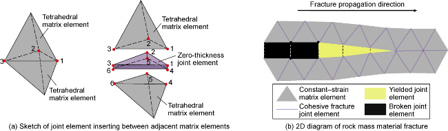
A numerical simulation model for deflagration fracturing was established based on the finite-discrete element method (FDEM). The continuum to be simulated was discretized into a finite number of tetrahedral element meshes. Joint elements with initial zero thickness and cohesive effects were inserted between adjacent matrix elements, sharing the same nodes at the coplanar locations (Fig. 1a) [19-23]. The joint elements possess strong cohesion, so rock damage and failure can be determined by the tensile and shear displacements of the joint elements, thereby simulating continuous deformation. When the tensile or shear displacement of the joint elements reaches the critical threshold, the joint elements get failed to form fractures [23] (Fig. 1b).
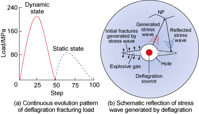
The formation and propagation of fractures in deflagration fracturing are primarily driven by the synergistic action of two loading mechanisms. At the initial stage of deflagration fracturing, the surrounding rocks are subjected to the tensile stress of stress wave to form initial radial fractures. As the dynamic stress field of the stress wave gradually weakens, the expansion of the explosive gas within the fracture generates a static pressure that further extends the initial fractures through the "gas cutting effect" [24]. Therefore, the dynamic load simulating the stress wave propagation is applied to the model in this paper, and then the static load simulating the gas expansion is applied (Fig. 2a). Since there are numerous natural fractures (NFs) in shale reservoirs, the propagation of stress waves can activate distant NFs and reflect to form tensile waves, which act on the propagating fractures (Fig. 2b) [25]. The peak load on the loading surface generated by the stress wave is calculated by the Conwep model [26] (Eq. (1)), and the static gas load is calculated by the Weibull function [27] (Eq. (2)):
1.2. Experimental design
Laboratory experiments of deflagration fracturing on large-size rock samples were carried out for validation. The shale outcrop samples from the Silurian Longmaxi Formation in the Luzhou area of the Sichuan Basin were selected, and then cut into cubic rock with dimension of 300 mm × 300 mm × 300 mm. The basic mechanical parameters are shown in Table 1. A cylindrical hole with a diameter of 20 mm and a height of 170 mm was pre-drilled at the center of the rock sample to simulate the open hole. The main components of the deflagration fracturing agent are RDX (C3H6N6O6), oxidizing agent (KClO4), coagulating agent, aluminum powder and combustion regulator (Cu2Cr2O5). The samples No. 1-3 were designed to investigate the influence of in-situ stress difference on deflagration fractures, with 2 g of fracturing agent placed in each cylindrical hole. The minimum principal stress was maintained at 4 MPa, while the maximum principal stresses were set at 8, 12, and 16 MPa, respectively. The stress condition applied to No.4 sample was consistent with that of No.3, and 4 g agent was placed in the hole to compare the effect of the agent quantity. First, the rock sample was lifted by a crane and placed into the holder. A 20 mm thick steel plate was placed between the sample and the loading surface. Subsequently, the designed stress conditions were applied to the sample using a hydraulic loading system. Finally, deflagration was initiated through the operation control system and detonation device (Fig. 3). During the experiment, peak load data and shape parameters were obtained by analyzing the load curve from the data acquisition system: The deflagration load obtained from the average of the peak loads for samples No.1-3 was 75 MPa, while the load for sample No.4 was 120 MPa; the shape parameter of the load curve was 1.5. After the experiment, the fracture propagation morphology of the rock samples was observed.
Table 1. Basic parameters of rock samples |
| Parameter | Value | Parameter | Value |
|---|---|---|---|
| Elasticity modulus | 35 GPa | Tensile fracture energy of matrix | 15 J/m2 |
| Poisson's ratio | 0.25 | Shear fracture energy of matrix | 450 J/m2 |
| Density | 2 650 kg/m3 | Matrix internal friction angle | 45° |
| Matrix cohesion | 30 MPa | Matrix tensile strength | 3 MPa |
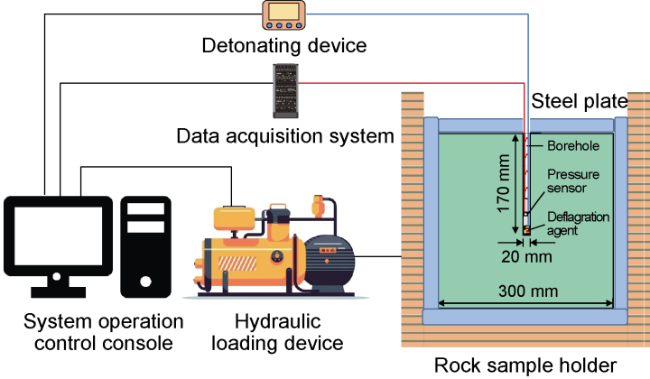
Fig. 3. Experimental devices of deflagration fracturing. |
1.3. Model validation
A numerical model with the same dimensions as the physical experiment was established, with an average element size of 1 mm (1/300 of the model’s characteristic length). The basic parameters and stress conditions of the model were consistent with the physical experiment (Table 1). From the experimental results of rock samples No. 1-3, it can be observed that as the in-situ stress difference increases, the fracture morphology evolves from three main fractures into a double-wing fracture parallel to the maximum horizontal principal stress (Fig. 4a-4c). These fractures extend from the center to the edge at the top of the rock samples, indicating that with the increasing in-situ stress difference, the propagation of deflagration fractures along the minimum horizontal principal stress is suppressed; By comparing the experimental results of rock samples No.3 and No.4, it can be concluded that increasing the amount of fracturing agent can form deflagration fracturing fractures that are not controlled by the differential in-situ stress (Fig. 4c, 4d). The comparison between experimental and numerical simulation results shows that the fracture propagation morphology is generally consistent (Fig. 4e-4h), which confirms the accuracy of the numerical model.
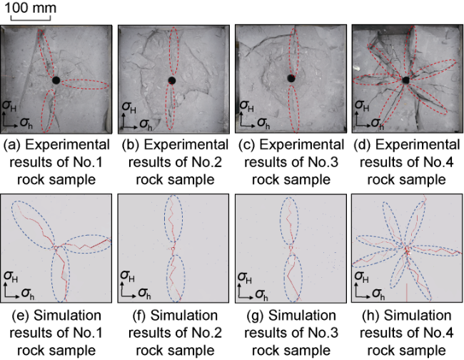
Fig. 4. Comparison of physical experiment and numerical simulation results. |
2. Analysis on influential factors of fracture propagation in branch well deflagration fracturing
2.1. Numerical model of deflagration fracturing in branch wells
A 3D model with dimension of 100 m × 100 m × 100 m for a double branch well and one of 100 m × 100 m × 200 m for a main wellbore-branch wellbore were established. The lengths of the parallel branched wells in these two models are both 80 m, and a deflagration section with a length of 5 m was set at the front end of the branch wells. The model assumes open-hole completion and neglects the effects of perforation hole. The solid boundaries contacted by the branch wells were set to have fixed normal displacements. A submodel structure was applied to eliminate the simulation distortion caused by the reflection of stress waves at the boundaries [20] (Fig. 5a). The basic parameters of the model are shown in Table 1 and Table 2. Each model contains randomly distributed 100 NFs with a dip of 0° to 75°, and is consistent in the rock mechanics parameters of the fractures, assuming that the fracture surface is square (Fig. 5b, 5c). The variation laws of the influential area were analyzed by calculating the damage zone of the surrounding rock mass after deflagration. The crush zone (5.76-7.41 mm) and fracture zone (0.82-5.76 mm) were classified according to the extracted width of deflagration fracturing fractures (Fig. 5d).
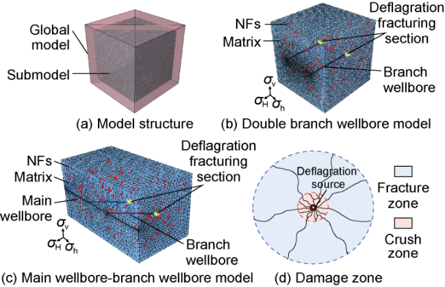
Fig. 5. Numerical model of deflagration fracturing and damage zone. |
Table 2. Basic parameters of branch well model |
| Parameter | Value | Parameter | Value |
|---|---|---|---|
| NF cohesion | 5 MPa | Maximum horizontal principal stress | 112 MPa |
| Tensile fracture energy of NF | 3 J/m2 | Vertical principal stress | 106 MPa |
| Shear fracture energy of NF | 32 J/m2 | Minimum horizontal principal stress | 97 MPa |
| NF tensile strength | 1 MPa | Peak load of the double branch wellbore model | 180 MPa |
| NF internal friction angle | 15° | Peak load of the main well- bore-branch wellbore model | 240 MPa |
A single-factor analyses was conducted on the in-situ stress difference, NF parameters (volumetric density, angle, and length), spacing between branch wellbores, delay detonation time, and the angle between branch wellbore and main wellbore to investigate their effects on fracture propagation in deflagration fracturing. The base parameters for simulation comparison were set as follows: in-situ stress difference of 15 MPa, NF volumetric density of 4×10⁻⁴ m2/m3, NF length of 2 m, spacing between branch wells of 48 m, delay detonation time of 0 ms, and the angle between branch wellbore and main wellbore of 90°. While keeping the base parameters constant, the values of the analyzed factors were altered to perform single-factor influence simulations.
2.2. The effect of in-situ stress difference
The in-situ stress difference was set to 5, 10, 15, and 20 MPa to simulate the morphology of deflagration fractures under different in-situ stress differences. When the in-situ stress difference ranged from 5 MPa to 15 MPa, the fracture propagation morphology and direction did not change significantly (Fig. 6a-6c). The load generated by the deflagration can overcome the suppressed effect of the current in-situ stress difference. However, when the in-situ stress difference reached 20 MPa, the number of deflagration fractures decreased, the tendency for fractures between branch wells to intersection weakened, and the probability of interference between branch wellbore was reduced (Fig. 6d). As shown in Fig. 7a, with the increase in in-situ stress difference, the length of fractures in the direction of the maximum horizontal principal stress gradually increases, while the length of fractures in the direction of the minimum horizontal principal stress decreases. The difference in fracture length between the two directions enlarges, and the suppressed effect on fracture propagation in the direction of the minimum horizontal principal stress becomes more significant, accompanied by a reduction in the volumes of the crush zone and fracture zone. NFs are classified into three grades based on their width: Grade I (4.94-7.41 mm), Grade II (2.47-4.94 mm), and Grade III (0-2.47 mm). The in-situ stress difference has less effect on the number of activated NFs (Fig. 7b), the activation of NFs is mainly determined by the reflection of stress waves during propagation, and the variation in in-situ stress difference has less effect on the efficiency of work done by stress waves.
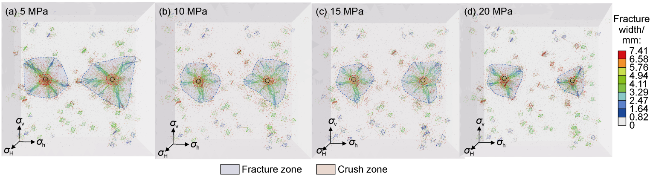
Fig. 6. Fracture morphology under different in-situ stress difference conditions for deflagration fracturing. |
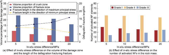
Fig. 7. Effect of in-situ stress difference on the damage zone, deflagration fracture length, and the number of activated NFs in deflagration fracturing. |
2.3. The effect of NF parameters
The NF volumetric density was set to 2×10⁻⁴, 4×10⁻⁴, 6×10⁻⁴ and 8×10⁻⁴ m2/m3. As depicted in Fig. 8a, under the simulation conditions of this study, the length of deflagration fractures gradually decreases with the increase of NF volumetric density, and the fracture propagation direction is deflected. NFs are primarily activated by stress waves, and the increase of NFs intensifies energy consumption, weakening the continuous propagation ability of initial fractures near the wellbore. The deflagration fracturing drives fractures to propagate radially by transiently releasing energy, but the presence of NFs suppress this process. Thus, in reservoirs with a high volumetric density of NFs, the propagation effect of deflagration fracturing fractures is suppressed.
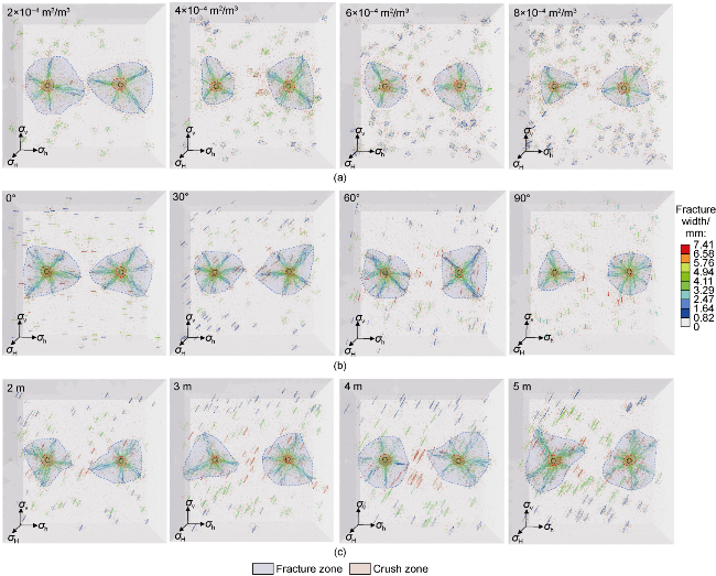
Fig. 8. Fracture morphology under different NF parameters for deflagration fracturing. (a) Fracture morphology under different NF volumetric densities; (b) Fracture morphology under different NF angles; (c) Fracture morphology under different NF lengths. |
The angle between NFs and the direction of minimum horizontal principal stress were set to 0°, 30°, 60°, and 90°, respectively. As shown in Fig. 8b, with the angle increasing from 0° to 90°, the length of deflagration fractures propagating in the direction of minimum horizontal principal stress generally decreases. When the angle is 0°, the tendency for fractures between branch wellbores to intersection is most significant, because NFs parallel to the line connecting wellbores provide a preferential pathway for fracture propagation between wellbores. As the angle increases to 90°, the propagation of deflagration fractures in all directions is significantly suppressed.
The lengths of NFs were set to 2, 3, 4 and 5 m, respectively (the angle between NFs and the direction of the minimum horizontal principal stress was fixed at 45°). The fracture propagation morphologies are shown in Fig. 8c. It can be illustrated that an increase in the length of NFs promotes the propagation of deflagration fracturing fractures along the direction of NFs, for deflagration fracturing fractures intersect with activated NFs during propagation and continue to extend propagate along the direction of NFs.
Fig. 9 shows that the volumetric density and angle of NFs are negatively correlated with the length of deflagration fractures and the volumes of crush zone and fracture zone. The length of NFs is positively correlated with the length of deflagration fracturing and the volume of crush zone. At a constant total deflagration energy, changing the NF parameters has a relatively minor impact on the activation degree of NFs.
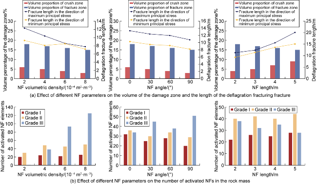
Fig. 9. Effect of different NF parameters on the damage zone, deflagration fracture length, and the number of activated NFs in deflagration fracturing. |
2.4. The effect of branch wellbore spacing
Deflagration fracturing was conducted simultaneously in two branch wellbores with the spacing of 20, 30, 40, and 50 m, respectively, to simulate the fracture morphology of deflagration fracturing. When the spacing is 20 m, the fractures between the branch wellbores intersect each other and are morphologically simple (Fig. 10a), and the fracture propagation direction is restricted by the wellbore spacing. This is attributed to the fact that at the initial stage of deflagration fracturing, the stress field at the midpoint of the line connecting the two deflagration sources is enhanced by the superposition of stress waves, resulting in a prominent stress concentration. As the spacing between branch wellbores gradually increases, the fracture zone around the wellbores expands progressively, the interference between the fractures and stress waves between the branch wellbores weakens, and the fractures get more and propagate in multiple directions. At spacing of 40 m (Fig. 10c), the tensile stress developed in the intermediate region between branch wellbores is insufficient to exceed the tensile strength of the rock. As a result, the rock fails to undergo fragmentation to form a fracture zone, and thus the phenomenon of fracture intersection between branch wellbores is weakened. As the spacing increases from 20 m to 50 m, the fracture intersection zone between the wellbores gradually disappears (Fig. 10d), while the volume of the crush zone decreases, and the length of deflagration fractures and the volume of the fracture zone increase (Fig. 11a). Changing the spacing between branch wellbores exhibits no significant regular impact on the number of activated NFs (Fig. 11b).
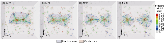
Fig. 10. Fracture morphology under different branch wellbore spacing for deflagration fracturing. |
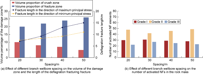
Fig. 11. Effect of branch wellbore spacing on the damage zone, deflagration fracture length, and the number of activated NFs in deflagration fracturing. |
2.5. The effect of delay detonation time
The first branch wellbore was set to be fractured first, while the second branch wellbore was detonated with a delay, with the delay detonation time of 0.1, 0.2, 0.3 and 0.4 ms, respectively. Within the simulation time range of this study, as the delay detonation time of branch wellbore 2 increases, the fracture propagation range of branch wellbore 1 becomes larger, with longer fractures and a broader damage zone (Fig. 12). The inter-well frac-hit phenomenon of deflagration fractures gradually intensifies, and the distance between inter-wellbore fractures gradually shortens. As the delayed detonation time increases, the fracture length of branch wellbore 2 along the direction of the minimum horizontal principal stress gradually increases, with the crush zone and fracture zone showing a tendency to expand (Fig. 13a). This trend leads to an increase in the number of activated NFs and intensified rock damage, thereby enhancing the activation rate of NFs near the wellbore (Fig. 13b). Therefore, when the delay time ranges from 0.1 ms to 0.4 ms, increasing the delayed detonation time increases the probability of fracture intersection between branch wellbores.
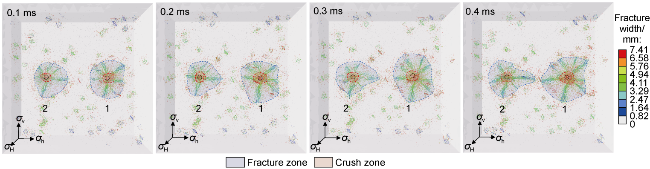
Fig. 12. Fracture morphology under different delay detonation time conditions for deflagration fracturing. |
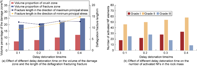
Fig. 13. Effect of delayed detonation time of No.2 wellbore on the damage zone, deflagration fracture length, and the number of activated NFs in deflagration fracturing. |
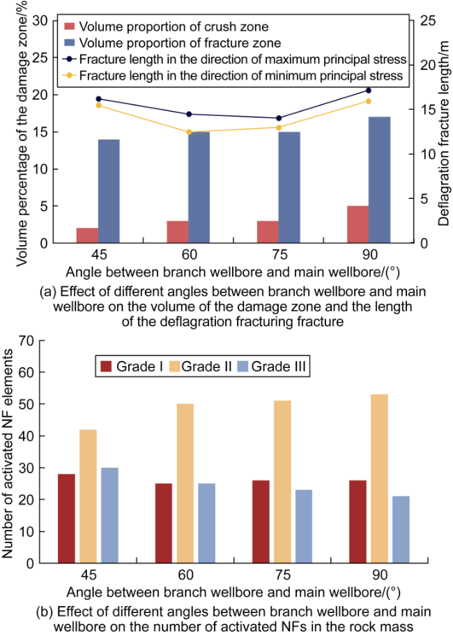
2.6. The effect of the angle between branch wellbore and main wellbore
The direction of the main wellbore was set to be parallel to that of the minimum horizontal principal stress, and the angles between the branch wellbores and the main wellbore were 45°, 60°, 75° and 90°, respectively. As the angle increases, there is no obvious law in the inter-wellbore fracture intersection (Fig. 14). At the angles of 45° and 90°, fractures between wellbores tend to intersection. At the angle of 45°, the deflagration fractures are less affected by the combined action of the maximum and minimum horizontal principal stresses, leading to uniform radial propagation of deflagration fractures with a circular contour of the fracture zone. At the angle of 90°, the morphology of the fracture zone evolves into an ellipse, and radial fractures show a distinct tendency to propagate along the direction of the minimum horizontal principal stress. According to the analysis, the deflagration fracture propagation direction is more influenced by the minimum horizontal principal stress at this angle. When the angle exceeds 60°, the fracture length in the direction of the minimum horizontal principal stress, and the volumes of crush zone and fracture zone present a gradual increasing trend. The angle between the branch wellbore and the main wellbore has less effect on the activation degree of NFs (Fig. 15).
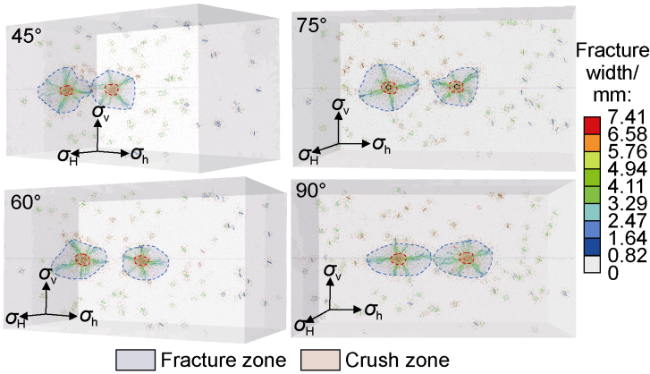
Fig. 14. Fracture morphology under different angles between branch wellbore and main wellbore for deflagration fracturing. |
Fig. 15. Effect of different angles between branch wellbore and main wellbore on the damage zone, deflagration fracture length, and the number of activated NFs in deflagration fracturing. |
3. Conclusions
Under the simulation conditions of this study, when the in-situ stress difference is between 5 MPa and 15 MPa, the fracture propagation morphology of deflagration fracturing is less affected by the in-situ stress difference; At an in-situ stress difference of 20 MPa, the number of deflagration fractures decreases, the tendency of fracture intersection between wellbores is significantly weakened, and the probability of inter-wellbore interference is reduced. The length of NFs is positively correlated with the length of deflagration fracturing fractures and the volume of the crush zone. A higher volume density and angle of NFs can suppress the fracture propagation area and reduce the probability of inter-well frac-hit.
When the spacing between branch wellbores is relatively small (20 m), inter-wellbore deflagration fractures are prone to intersection. As the well spacing increases to 50 m, the interference between fractures and stress waves between the branch wellbores weakens, allowing the fractures to propagate in multiple directions and gradually increasing the volume of the fracture zone. Increasing the delay detonation time shortens the distance between inter-wellbore fractures. The damage range of the first-fractured branch wellbore is larger, leading to an increase in the number of activated NFs and a greater degree of rock damage. When the angle between the branch wellbore and the main wellbore is 45° and 90°, there is a tendency for inter-wellbore deflagration fractures to intersect.
Nomenclature
g—static load loading step, dimensionless;
g0—parameters related to the mean of distribution function, dimensionless;
m—shape parameter of Weibull distribution function, dimensionless;
p(t)—load generated by the stress wave on the loading surface at time t, MPa;
pg(g)—pressure of gas under static action, MPa;
pg0—base load related to pg peak, MPa;
pi—incident wave overpressure, MPa;
pr—reflected wave overpressure, MPa;
t—time, ms;
θ—angle between the loading surface and the vector pointing from the loading surface to the deflagration source, (°);
σH, σh, σv—maximum and minimum horizontal principal stress, and vertical principal stress, MPa.