

Introduction
As one of the most significant greenhouse gases, CO2 primarily originates from fossil fuel combustion, industrial activities, and natural processes. As of 2024, the global average surface temperature has reached a historical high since meteorological records began in 1850, exceeding pre-industrial levels by 1.5 °C [1]. Concurrently, global ocean heat content has also reached a new record, accompanied by accelerated glacier melting, rising sea levels, and frequent extreme weather events such as heavy rainfall, flooding, and heatwaves [2]. The adverse impacts of global climate change have proven to be more profound and severe than previously anticipated, emerging as a critical challenge that demands urgent and collective action from all of humanity.
In the face of the global climate crisis, actively promoting the energy transition has become a shared responsibility for countries worldwide. However, the rapid growth of renewable energy has not yet substantially altered the dominance of fossil fuels across the globe. Fossil fuels still account for approximately 80% of the global energy supply. In 2024, carbon emissions from coal, oil, and natural gas increased by 2%, 0.3%, and 3.7%, respectively, year-on-year, pushing total emissions to a historic high of 37.8 billion tons [3-4]. This trend deviates from the climate goal of “limiting the global temperature rise to within 1.5 °C above pre-industrial levels.” Compounded by the accelerated pace of global warming in recent years, it is imperative to implement strong and effective measures to halt the continuous rise in atmospheric CO2 concentrations.
CO2 Capture, Utilization, and Storage (CCUS) refers to a suite of technologies designed to separate and capture CO2 from industrial processes, energy production, or directly from the atmosphere, and then transport the captured CO2 via pipelines or ships to suitable sites for utilization or permanent storage, ultimately reducing CO2 emissions. By mitigating the adverse effects of carbon emissions, CCUS holds significant potential for achieving global carbon neutrality goals [5-7]. CCUS encompasses three main technological pathways: Carbon Capture and Storage (CCS), Carbon Capture and Utilization (CCU), and Carbon Dioxide Removal (CDR). CCS involves injecting CO2 into deep geological formations for permanent isolation from the atmosphere, thereby preventing its release. CCU treats CO2 as a reusable resource, transforming it into valuable products to generate economic benefits. CDR focuses on actively reducing the concentration of CO2 in the atmosphere, achieving negative emissions. Together, these complementary technologies address both the environmental and economic challenges posed by greenhouse gas emissions. According to data from the International Energy Agency (IEA), CCUS is projected to contribute approximately 14% of the necessary CO2 emission reductions by 2050, with its share increasing to around 32% by the end of the century [8]. This paper focuses on the capture, utilization, and storage components of CCUS. It reviews the current global development status and, with particular emphasis on industrial sectors such as oil and gas, examines key technological advances, existing bottlenecks, and priority areas for future research and development.
1. Current status of CCUS in major countries and regions
1.1. North American regions
North America, as a global pioneer in CCUS technology, has demonstrated a distinct phased evolution in its technological development. In its early stages, CCUS applications were predominantly concentrated within the oil and gas industry, where CO2-Enhanced Oil Recovery (CO2-EOR), particularly in the United States, emerged as the dominant model. The global first large-scale CO2-EOR project, SACROC (Fig. 1), was successfully implemented in 1972 in the oil-producing region of Western Texas. This project achieved daily CO2 injection rates exceeding 5 000 t, cumulative CO2 injection of approximately 175 million tons and cumulative oil production of around 43 million tons [9-10]. This success delivered substantial economic and environmental benefits. The mature development of CO2-EOR technology in the United States has been supported by several key factors. Firstly, abundant natural CO2 reservoirs are widely distributed near major oil-producing regions, providing a stable and accessible gas source. Secondly, extensive expertise and engineering experience in hydrocarbon gas flooding, accumulated since the 1950s, have significantly enhanced the reliability and effectiveness of CO2 injection applications. According to statistics from the U.S. Department of Energy (DOE), approximately 30-50 million tons of CO2 are injected annually for EOR purposes in the United States. This practice successfully achieves the dual objectives of enhancing energy production while reducing carbon emissions, and has now evolved into an industry with an annual operational scale exceeding tens of millions of tons.
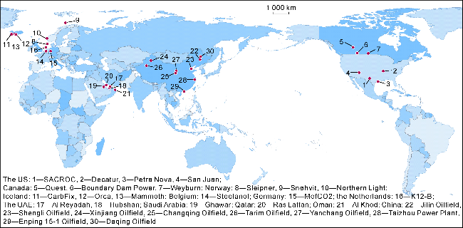
Fig. 1. Distribution of typical CCUS projects in the world. |
North America has made notable progress in CO2 storage in saline aquifers and depleted oil and gas reservoirs. For instance, the total estimated storage capacity in saline aquifers within Canadian sedimentary basins alone exceeds 100 billion tons, with basins such as the Western Canada Sedimentary Basin and the Williston Basin being identified as highly suitable for CO2 storage [11]. A prominent example is the Quest million-ton-scale saline aquifer storage project. By capturing CO2 from oil sands operations and injecting it into deep geological formations, Quest has sequestered over 9 million tons of CO2 cumulatively as of 2024 [12]. In the United States, the Decatur project in Illinois is another significant demonstration of saline aquifer storage. Designed for an annual sequestration capacity of 1 million tons, this project exemplifies the application potential of CCUS within heavy industry sectors.
With the enhancement of environmental regulations and the widespread adoption of carbon-neutral power goals across North America, CCUS technology is increasingly being directed toward reducing industrial CO2 emissions [13]. In Canada, the Boundary Dam Power Station project, one of the global first commercial-scale CCS facilities integrated with a power plant, has captured over 7 million tons of CO2 since its commissioning in 2014. This project has successfully validated the technical and operational feasibility of retrofitting traditional fossil fuel power stations into near-zero-emission facilities [14]. In the United States, the Petra Nova project, which began operation in 2017 and was once one of the global largest post-combustion carbon capture facilities at a coal-fired power plant, demonstrated an annual CO2 capture capacity of approximately 1.6 million tons. The captured CO2 was utilized for EOR [15]. Furthermore, novel carbon capture and utilization technologies continue to evolve in North America. Canada has commercially deployed Point Source Capture (PSC) technology, achieving capture efficiencies exceeding 90%. Concurrently, significant investments from the U.S. federal government and private enterprises are accelerating the development of large-scale Direct Air Capture (DAC) projects [15].
1.2. European region
In contrast to North America, Europe places greater emphasis on establishing stringent environmental regulations and fostering transnational coordination. It regards CCUS as a critical technological pillar for achieving net-zero emissions, comparable in strategic importance to hydrogen energy. Currently, the comprehensive technical cost for typical CCUS projects in Europe ranges from €100 to €200 per ton. The economic viability of achieving emission reductions through CCUS heavily depends on the carbon price within the EU Emissions Trading System (EU ETS). To accelerate deployment, the European Commission released both the Industrial Carbon Management Strategy and the Net-Zero Industry Act in 2024. These key policy documents explicitly outline the goal of expanding the scale of commercial CCUS deployment. They aim to systematically plan and construct a zero-carbon industrial system, thereby accelerating the decarbonization of industrial enterprises and strengthening European technological and industrial leadership in this field.
In Europe, particular emphasis is placed on the safe development of subsurface CO2 storage technologies, with active promotion of marine geological storage demonstration projects. This commitment is formally reflected in the Net-Zero Industry Act, which sets a target for the region to achieve an annual CO2 injection capacity of 50 million tons by 2030. The majority of European CCUS demonstration projects are concentrated in the North Sea and the Netherlands, each exhibiting distinct regional characteristics in project design and technical pathways. The Sleipner project in the Norwegian North Sea, operational since 1996, is the global first large-scale CO2 storage initiative, with annual CO2 storage capacity of approximately 1 million tons and cumulative total exceeding 20 million tons [16]. In the Netherlands, the K12-B project, commissioned in 2004, pioneered the global first offshore CO2 injection for Enhanced Gas Recovery (CO2-EGR) in a depleted gas field. This project successfully validated the technical feasibility of injecting CO2 into deep sandstone formations offshore [17]. Another landmark initiative is the Northern Lights project in Norway, the first cross-border, open-access CO2 transport and storage infrastructure network. It utilizes a 100 km pipeline to transport captured CO2 for permanent storage in a saline aquifer located 2600 meters beneath the seabed. With an initial capacity of 1.5 million tons per year, the project is planned for expansion to 5 million tons annually by 2025 [18]. In Iceland, the CarbFix project has introduced a groundbreaking paradigm for onshore carbon storage by achieving ultra-high mineralization storage efficiency through the injection of CO2 into basalt formations [19].
European enterprises are strategically focusing on the chemical conversion and resource utilization of CO2 in areas such as fuel synthesis, chemical production, and building material manufacturing, driving the development of a carbon circular economy. In Belgium, the Steelanol project utilizes CO2 captured from steel mill flue gas as a feedstock to produce ethanol. This facility has an annual production capacity of up to 80 million liters of ethanol, while concurrently reducing carbon emissions by approximately 125 000 t per year [20]. In Germany, the MefCO2 project successfully integrated CO2 emissions from a coal-fired power plant with green hydrogen, produced via water electrolysis powered by renewable energy, to synthesize methanol. Operational until its completion in 2019, the project demonstrated an annual methanol output of around 400 t. A key achievement was proving the technical viability of stable, flexible operation under fluctuating renewable power supply, thereby providing a crucial technological validation for the low-carbon transition of the chemical industry [21].
1.3. Middle East region
The Middle East, possessing the global most abundant hydrocarbon reserves and enjoying the lowest extraction costs, has initiated a strategic deployment of CCUS technologies in recent years. The mature infrastructure for oil and gas production and pipeline transportation in the region offers significant logistical advantages for the large-scale transport and storage of CO2. Furthermore, the concentration of major ports and industrial clusters establishes a strong foundation for developing integrated regional CO2 pipeline networks.
The Gulf Cooperation Council (GCC) nations, notably the United Arab Emirates (UAE) and Saudi Arabia, have positioned CCUS as a critical pillar of their energy transition and low-carbon development strategies, implementing several landmark projects. In the UAE, the Al Reyadah project in Abu Dhabi, launched in 2016, marked the first large-scale CCUS initiative in the Middle East, capturing approximately 800 000 t of CO2 annually from an Emirates Steel plant and injects it via a dedicated pipeline into the Rumaitha and Bab oil fields for EOR [22]. In 2023, Abu Dhabi National Oil Company (ADNOC) announced the investment in the Habshan project, which aims to capture CO2 from natural gas processing facilities for use in EOR operations. With a projected capacity to capture and permanently sequester up to 1.5 million tons of CO2 per year, this project is planned to become the largest CCUS facility in the Middle East and North Africa region [15]. Saudi Arabia is also leveraging its vast resources for CCUS application. The giant Ghawar oil field of the nation serves as a demonstration site for CO2-EOR, utilizing around 800 000 t of CO2 per year sourced from natural gas processing plants [23]. Furthermore, QatarEnergy is implementing large-scale carbon capture from its liquefied natural gas (LNG) facilities at the Ras Laffan Industrial City. The current operation captures about 2.2 million tons of CO2 annually, with a cumulative total processed exceeding 7.5 million tons to date. Plans are underway to significantly expand this capture capacity to 7 million tons per year by 2030, supporting the strategy of Qatar for supplying lower-carbon LNG [24]. Beyond point-source capture for EOR, the region is exploring innovative geological storage pathways. Notably, Oman possesses vast exposures of pyrolite estimated at around 15 000 km³, which hold immense potential for permanent CO2 sequestration through mineral carbonation. Research and pilot studies, such as those in the Al Khod area, are accelerating to develop this technology, with a long-term goal of achieving a sequestration capacity of 1.5 million tons of CO2 per year [25].
The Gulf Cooperation Council (GCC) countries collectively capture approximately 3.7 million tons of CO2 annually, accounting for about 10% of the global total. Ambitious national roadmaps estimate that this figure could rise dramatically to an estimated 60 million tons per year by 2035 [26]. Strategically, Middle Eastern nations are leveraging their resource wealth and financial capital to position CCUS technology as a dual-purpose pathway: sustaining the long-term competitiveness of their hydrocarbon sectors while simultaneously advancing domestic low-carbon transitions. By actively pursuing cross-border carbon trading partnerships and international technology cooperation, particularly with markets in Europe, Africa, and East Asia, these countries aim to secure a new form of geopolitical and economic advantage in the evolving global energy landscape.
1.4. China
In contrast to many international counterparts, the development of CCUS projects in China is predominantly led by state-owned enterprises (SOEs). The national strategy emphasizes strong policy guidance and technological innovation to achieve carbon emission control and foster the CCUS industry. This approach centers on developing three key categories of green, low-carbon technologies, i.e., source carbon reduction, process carbon abatement, and end-of-pipe carbon sequestration [27]. By strategically aligning resource endowments with national decarbonization goals, China is cultivating a series of distinctive integrated pathways, notably “Coal-Power + CCUS” and “Oil & Gas + CCUS”.
The existing coal-fired power plants of China represent the primary target for the application and promotion of CCUS technology. In this context, the Taizhou Power Plant CCUS demonstration project in Jiangsu Province, developed by China Energy Investment Corporation, stands as the largest coal-fired CCUS facility currently operating in Asia, with an annual capture capacity of 500 000 t and a capture efficiency exceeding 90%. Meanwhile, China Shenhua Energy Company has implemented multiple CCUS initiatives across its coal mining and combustion operations, conducting capture-and-storage pilot projects in mining areas such as Inner Mongolia and Xinjiang. A notable cross-sectoral collaboration has also emerged in the Ningdong Energy and Chemical Industry Base in Ningxia, where a partnership between modern coal-chemical plants and large oil-and-gas fields aims to achieve an annual CO2 reduction of 3 million tons. Given the inherent abundance of coal resources in China and the fact that coal-fired power still accounts for approximately half of the national electricity mix, coal-based generation is expected to remain a critical “ballast” for grid stability and energy security for the foreseeable future. Against this backdrop, advancing “coal power + CCUS” technologies represent a practical and economically viable pathway to address the large existing stock of coal-fired assets [28].
Apart from the high-emission coal-power sector, oil and gas enterprises in China possess inherent advantages and a solid foundation for developing CCUS, giving rise to a distinct “Oil & Gas Industry CCUS Model” (Fig. 2). By May 2025, China National Petroleum Corporation (CNPC) had cumulatively sequestered over 10 million tons of CO2, accounting for approximately 65% of the total injected volume of China, while increasing oil production by more than 3.3 million tons. CNPC has established industrial-scale CCUS demonstrations across multiple oil fields, including Jilin, Xinjiang, Changqing, and Tarim. Sinopec has also made significant strides with its Shengli Oilfield million-ton-scale CCUS project. This facility captures CO2 from industrial off-gas for use in EOR, improving recovery rates in low-permeability reservoirs by over 12 percentage points. Similarly, Yanchang Petroleum has integrated coal chemical operations with CO2 resource utilization, achieving the safe sequestration of about 400 000 t of CO2 and an incremental oil production of 202 000 t through CO2 fracturing by the end of 2024, establishing a whole-process CCUS demonstration. A landmark development is the first offshore CCUS project of China, commissioned in 2025 at the Enping 15-1 platform in the Pearl River Mouth Basin. As of October that year, it had cumulatively stored over 100 million cubic meters of CO2. The project plans to inject more than 1 million tons of CO2 over the next decade, providing coastal enterprises with a scalable technical blueprint for large-scale emission reductions. In parallel with actively building near-zero-emission oil and gas field demonstration zones, the China National Energy Administration has issued a policy white paper to promote the transformation and upgrading of the petroleum refining and chemical industry. This includes strengthening R&D and application in areas such as renewable energy-based hydrogen production and the hydrogenation of CO2 to produce chemical products [29].
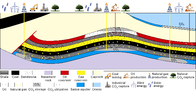
Fig. 2. CCUS model of oil and gas industry. |
2. CCUS technological progress
2.1. CO2 capture
CO2 capture refers to a suite of technologies that employ physical, chemical, or biological methods to separate CO2 from mixed gas streams emitted during industrial and energy production processes, and then treat or store the captured CO2 collectively. The primary objective is to reduce direct emissions from these critical sectors, positioning CO2 capture as a key strategic pillar in the global response to climate change.
Based on the stage at which capture occurs, the main technologies can be categorized into three types: pre-combustion capture, oxy-fuel combustion capture, and post-combustion capture. Pre-combustion capture involves converting fossil fuels into a syngas composed of CO and H2 before combustion. The CO in the syngas is then shifted to CO2 via a water-gas shift reaction, after which the CO2 is separated using physical or chemical methods. Oxy-fuel combustion capture replaces conventional air with pure oxygen or oxygen-enriched air for combustion. This results in a flue gas with a high concentration of CO2, which can be captured directly. Post-combustion capture separates and concentrates CO2 from the flue gas after fuel combustion. This is currently the most widely applied method in industry, particularly well-suited for the retrofitting and upgrading of existing power plants [30].
Based on the underlying separation principles, CO2 capture technologies can be classified into chemical absorption, physical adsorption, membrane separation, and cryogenic separation [31]. Chemical absorption is currently the predominant technology, employing liquid solvents to react with CO2 to form reversible compounds. Commonly used absorbents include amine-based solutions such as monoethanolamine (MEA), diethanolamine (DEA), and N-methyldiethanolamine (MDEA). In this process, CO2 chemically binds with the amine, and the resulting compound is later thermally decomposed in a regeneration step (through heating and/or pressure reduction) to release a concentrated CO2 stream while regenerating the solvent. This method offers high efficiency and is suitable for large-scale industrial applications, with the technological development of China in this area being on par with international advanced levels. Beyond amines, alternative absorbents such as amino acid salts, ionic liquids, and ammonia solutions are also under research for chemical absorption [32-34]. The primary drawbacks of this method are large loss of absorbent, and high energy demand for solvent regeneration, along with challenges related to solvent handling. Physical adsorption relies on porous solid materials, such as molecular sieves, activated carbon, zeolites, and carbon nanomaterials, to adsorb CO2 [35-36]. Its advantages include relatively simple operation, lower energy consumption, and high recovery efficiency. However, its capture capacity is often limited and typically requires low temperatures or high pressures to achieve significant CO2 uptake. Adsorbent lifespan can also be a constraint due to fouling or degradation. This method is generally suitable for gas streams with high CO2 partial pressure and where a very high purity of the separated gas is not required. Membrane separation technology utilizes the selective permeability of membrane materials to separate CO2 from a gas mixture. Common membrane materials include cellulose acetate, ethyl cellulose, polyimide, polyethersulfone, polyphenylene oxide, and composite membranes [37-38]. The selection of a membrane depends on a careful balance of permeability, selectivity, chemical/thermal stability, and cost-effectiveness for the specific application. While membrane systems offer advantages such as high separation efficiency, operational simplicity, and a compact footprint, their widespread adoption is challenged by requirements for membrane durability under real-world conditions and overall system economics. Cryogenic separation leverages differences in the condensation temperatures of gases. The gas mixture is cooled to very low temperatures, causing CO2 to liquefy and separate. This method achieves high CO2 capture efficiency and is well-established in large-scale applications like natural gas processing. Its main limitation is the significant energy consumption required for the cooling processes.
As an emerging generation of carbon capture technology, Direct Air Capture (DAC) extracts CO2 directly from ambient air, offering advantages in deployment flexibility and site adaptability. It is applicable not only to fixed emission sources like power plants and chemical facilities but also to distributed, non-point sources such as agriculture and transportation. Currently, the primary technical pathways for DAC are solid sorbent adsorption and liquid solvent absorption. A prominent leader in the solid adsorption route is Climeworks. The Orca plant of the company in Iceland, commissioned in 2021, was followed by the larger Mammoth plant in 2024. Both facilities utilize solid amine-based sorbents, with annual capture capacity scaling from thousands of tons to tens of thousands of tons [39]. In the liquid absorption domain, Canadian Carbon Engineering employs a process using a potassium hydroxide (KOH) solution to absorb atmospheric CO2, forming carbonate This approach is designed for continuous operation and offers significant potential for industrial-scale amplification [40]. Furthermore, research teams at the Zhejiang University have developed a novel self-supporting moisture-swing adsorption membrane for DAC. This technology modulates the material’s CO2 desorption behavior by controlling environmental humidity. Scaling tests have confirmed its potential for future industrial application [41].
Chemical Looping Combustion (CLC) represents a highly promising low-cost carbon capture technology. Conceptually and mechanistically, it belongs to the oxy-fuel combustion family. CLC utilizes oxygen carrier materials to transfer oxygen from air to the combustion process, avoiding direct contact between fuel and air, thereby achieving inherent CO2 capture at the source. The process operates through two interconnected reactors, enabling cascaded energy utilization with high overall system efficiency. Compared to conventional capture technologies, studies suggest that CLC can potentially reduce the cost of carbon capture by more than 50% [42-43]. Common metal oxides such as CuO, Fe2O3, NiO, and Mn3O4 can serve as effective oxygen carriers [44]. Pioneering development has been demonstrated globally. For instance, the Technical University of Darmstadt in Germany successfully commissioned a 1 MW pilot CLC unit in 2012 [45]. A significant recent milestone was achieved in 2024 by Dongfang Boiler Group Co., Ltd. (part of Dongfang Electric Corporation) in collaboration with a research consortium including Tsinghua University. Their project established a world-record 5 MW thermal input CLC system, achieving a maximum CO2 capture efficiency of up to 95%. This advancement strongly indicates that CLC technology has now progressed to a stage of readiness for initial commercial and large-scale applications [46].
The aforementioned CO2 capture methods were comparatively analyzed from the aspects such as typical solvent/material systems, operating temperature, energy consumption, cost, capture efficiency, current scale of installation, technological maturity, and primary application scenarios, as presented in Table 1.
| Capture method | Typical solvents/materials system | Operation system/°C | Energy required per 1 t CO2/GJ | Cost per 1 t CO2/ RMB | Capture efficiency/ % | Existing device scale | Technology maturity | Applicable scenarios |
|---|---|---|---|---|---|---|---|---|
| Physical adsorption | Zeolite, activated carbon, MOFs | 60-100 | 1.5-2.5 | 200-400 | 70.0-90.0 | Ten thousand tons class | Commercial application | Medium and high pressure gas, natural gas deacidification, hydrogen purification |
| Chemical adsorption | Amine solution (MEA, DEA, MDEA) | 85-120 | 2.0-4.0 | 300-500 | 80.0-95.0 | Million tons class | Commercial application | Large industrial flue gas capture such as thermal power, steel, cement and so on |
| Membrane separation | Polymer film, Inorganic film | <100 | 1.5-2.5 | 400-700 | 70.0-90.0 | Ten thousand tons class | Industrial demonstration | Small and medium-sized continuous separation such as natural gas deacidification, chemical tail gas treatment |
| Cryogenic separation | -140 to -70 | 4.0-7.0 | 500-800 | 95.0-99.9 | Ten thousand tons class | Industrial demonstration | Separation of high CO2 concentration associated gas, and purification of high pressure gas, natural gas, and hydrogen | |
| Direct air capture | Solid amine, strong alkali solution | 80-120 (Solid); 700-900 (Liquid) | 7.0-12.0 | 2 000- 4 000 | 60.0-90.0 | Ten thousand tons class | Industrial demonstration | Distributed, low concentration carbon capture |
| Chemical looping combustion capture | Metal oxides, oxygen carriers | 800-1 200 | 1.0-2.5 | 200-400 | 70.0-99.0 | Ten thousand tons class | Industrial demonstration | Integrated capture of combustion process |
The emergence of novel carbon capture materials has significantly expanded the possibilities for efficient CO2 adsorption. Metal-Organic Frameworks (MOFs) [47-48] and Covalent Organic Frameworks (COFs) [49-50] exhibit exceptional selective adsorption capabilities due to their adjustable pore structures and surface chemistries. Through systematic design, the pore architecture and chemical adsorption sites can be precisely engineered to foster highly efficient host-guest interactions between the framework and CO2 molecules. Concurrently, substantial research focus is directed toward the development of advanced polymer membranes. Polymers of Intrinsic Microporosity (PIMs), characterized by rigid and contorted polymer backbones, form interconnected sub- nanometer microporous structures within the material, which confer high ion conductivity to the resulting membranes. Polymeric Ionic Liquids (PILs), derived from the polymerization of ionic liquid monomers, combine low volatility, high solvation capacity, and tunable selectivity. These materials enable large-scale CO2 capture across a wide range of temperatures, pressures, and gas compositions. Mixed Matrix Membranes (MMMs) represent another promising avenue, integrating the superior flexibility and processability of polymer matrices with the excellent gas permeation and separation properties of inorganic fillers. This hybrid approach effectively balances the trade-off between permeability and selectivity, making MMMs highly suitable for separating CO2 from gas mixtures containing nitrogen, methane, or hydrogen [54-56]. Furthermore, gas hydrates have emerged as a ideal medium for CO2 separation and storage thanks to their unique cage-like crystalline structures and weak van der Waals forces [57].
2.2. CO2 utilization
Carbon dioxide utilization (CDU) technology aims to transform captured CO2 into, or substitute it for, valuable chemicals, fuels, or other products. This encompasses various approaches such as geological, chemical, biological, and mineralization-based utilization. CDU facilitates the resource-oriented use of CO2, while extending the carbon industrial chain.
2.2.1. CO2 geological utilization
The core mechanism of CO2 geological utilization involves injecting captured CO2 into subsurface oil and gas reservoirs to enhance resource recovery. This technique is applicable to various hydrocarbon resources, including conventional oil and gas, shale oil and gas, tight oil and gas, and coalbed methane. By increasing reservoir pressure and improving fluid mobility, CO2 injection significantly enhances the hydrocarbon recovery factor from these formations. Concurrently, a substantial portion of the injected CO2 becomes permanently sequestered within the geological formation. Thus, this approach serves as a dual-purpose solution, effectively combining enhanced resource production with long-term carbon storage and emission reduction.
Among these methods, CO2-enhanced oil recovery (CO2-EOR) technology accounts for over 45% of all CCUS projects globally. In China, pioneering experimental research began in the Daqing Oil Field in the 1960s. Through sustained development, this technology has achieved industrial-scale application across multiple major petroliferous basins, including the Songliao, Bohai Bay, Ordos, and Junggar Basins. The CO2-EOR process involves injecting CO2 into an oil reservoir. Under the reservoirs specific temperature and pressure conditions, CO2 exists in a supercritical state, exhibiting properties of both a gas and a liquid. This unique supercritical fluid possesses excellent solubility and extraction capability within crude oil. Its injection leads to multiple beneficial effects: viscosity reduction, oil swelling, and miscibility. Technical analyses demonstrate significant advantages over conventional waterflooding: the gas injectivity index during CO2 injection can be five times higher, while the initiation pressure is reduced by approximately 50%, leading to an injection capacity improvement of 2 to 6 times. This allows the process to act more effectively within narrow micro- and nano-scale pores. Furthermore, it avoids the damage to water-sensitive reservoirs. Under optimal pressure and well management conditions, CO2-EOR can increase the ultimate oil recovery factor by an additional 10 to 20 percentage points compared to waterflooding [58-59].
Based on phase behavior, CO2-EOR processes are classified into three types: miscible, immiscible, and near-miscible (or partially miscible) displacement. Miscible displacement occurs when the reservoir pressure exceeds the minimum miscibility pressure (MMP). Through multiple contacts, CO2 and crude oil achieve dynamic miscibility, where the interfacial tension between them approaches zero. This creates a highly mobile miscible zone with efficient mass transfer, leading to significantly improved oil displacement efficiency [60]. Immiscible displacement takes place at lower reservoir pressures where the two phases remain distinct. The displacement front is often unstable, prone to viscous fingering, which reduces sweep and displacement efficiency. Near-miscible displacement represents an intermediate state where CO2 and crude oil approach but do not fully achieve miscibility, exhibiting partial miscible characteristics [61-62]. Within a certain operating window, a higher degree of miscibility and lower interfacial tension directly correlate with higher displacement efficiency. This can be achieved by increasing reservoir pressure or by reducing the MMP. Both theoretical studies and field applications confirm that miscible and near-miscible processes yield superior development outcomes. Consequently, a key research focus is developing efficient miscibility enhancers (or co-solvents) that are cost-effective, environmentally compatible, and capable of modifying phase behavior to lower the MMP [63]. Typical additives include light hydrocarbon compounds with miscibility-enhancing properties, such as benzene derivatives and petroleum ethers. Furthermore, composite surfactant systems also exhibit superior synergistic performance in promoting miscibility.
The technology utilizing CO2 as a fracturing fluid was first proposed in 1981 [64]. This method employs liquid or supercritical CO2 to create complex fracture networks within geological formations through high-pressure injection, effectively stimulating reservoirs to enhance oil and gas production. A significant portion of the injected CO2 is sequestered long-term within the formation post-fracturing, with potential storage reaching thousands of tons per well. This has spurred the development of “negative-carbon fracturing” technologies [65-66]. Compared to conventional water-based fracturing fluids, CO2 exhibits superior penetration capability. It can permeate deep into fracture tips, generating more intricate and complex fracture networks. This approach also circumvents common challenges associated with water-based fluids, such as difficult flowback, high water consumption, and potential formation damage [67]. Due to its low viscosity and compressibility, CO2 can more readily access nano-scale pore throats under high-pressure, high-rate injection conditions. This makes it particularly suitable for stimulating low-permeability reservoirs like shale oil/gas and tight oil. However, the low viscosity of CO2 also results in poor proppant transport efficiency. This limitation can be mitigated by adding viscosifiers to the fluid or by deploying novel proppants.
2.2.2. CO2 chemical utilization
The core principle of chemical utilization is to convert CO2 into higher-value chemicals or fuels through chemical reactions. Given the inherent stability of the CO2 molecule, with a high C=O bond energy of approximately 750 kJ/mol, its reduction or functionalization typically requires significant energy input. This is facilitated by employing catalysts, elevated temperature and pressure conditions, or external energy sources such as light or electrical fields. The primary technological pathways for this conversion include CO2 hydrogenation catalysis, CO2 copolymerization, and CO2 photoelectrocatalysis, as summarized in Table 2.
Table 2. Chemical conversion pathway of CO2 |
| Reaction type | Products | Chemical equation | Application direction |
|---|---|---|---|
| Hydrogenation | CO | CO2+H2→CO+H2O | Chemical raw materials, synthesis gas, metallurgical reducing agent, etc. |
| CH3OH | CO2+3H2→CH3OH+H2O | Liquid hydrogen storage, clean fuels, organic solvents, chemical intermediates, etc. | |
| HCOOH | CO2+H2→HCOOH | Chemical raw materials, hydrogen storage carriers, fuel cells, etc. | |
| CH4 | CO2+4H2→CH4+2H2O | Synthetic natural gas, clean fuel, chemical raw materials, etc. | |
| Dimethyl carbonate | CO2+3H2→CH3OH+H2O CO2+2CH3OH→CO(OCH3)2+H2O | Green solvents, battery electrolytes, gasoline additives, etc. | |
| Electrochemical reduction | HCOOH | CO2+2H++2e-→HCOOH | Chemical raw materials, hydrogen storage carriers, fuel cells, etc. |
| CH3OH | CO2+6H++6e-→CH3OH+H2O | Liquid hydrogen storage, electric drive CO2 conversion complementary to the thermal catalytic route | |
| Ethylene | 2CO2+12H++12e-→C2H4+4H2O | Plastic monomer, basic chemical raw materials, etc. | |
| Ethanol | 2CO2+12H++12e-→C2H5OH+3H2O | Renewable fuels, organic solvents, chemical intermediates, etc. | |
| Organic synthesis and polymerization reaction | Synthetic urea | 2NH3+CO2→(NH2)2CO+H2O | Fertilizer, urea-formaldehyde resin, feed additives, etc. |
| Polycarbonate | 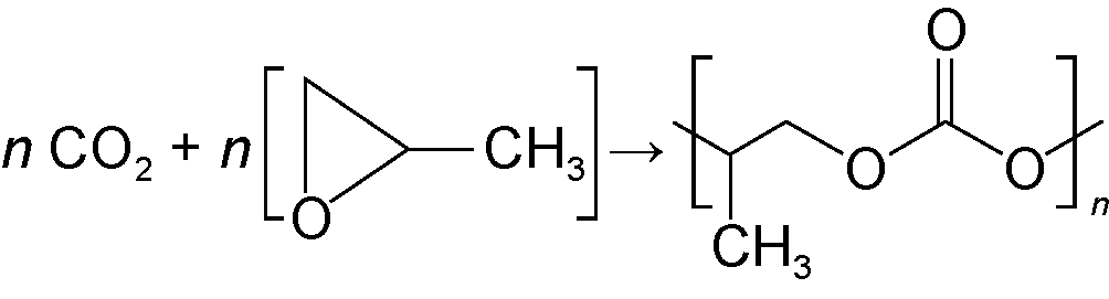 | Engineering plastics, biodegradable materials, etc. | |
| Cyclic carbonates | 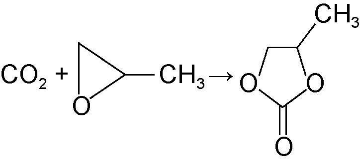 | Degradable plastic raw materials, battery electrolyte components, green solvents, etc. |
CO2 hydrogenation catalysis represents currently the most mature technology for the resource utilization of CO2, and it is primarily used to synthesize low-carbon products, such as methanol [68], formic acid [69], methane, carbon monoxide, and light olefins. These low-carbon products serve as versatile building blocks, enabling the downstream production of a wide range of high-value derivatives, including gasoline and diesel-range liquid hydrocarbons [70-71] and various higher alcohols [72]. The reaction pathways and final product distribution in CO2 hydrogenation are highly dependent on the selected catalyst system [73]: Copper-based catalysts, particularly Cu/ZnO, are extensively applied to methanol synthesis due to their excellent low-temperature activity and high conversion rate [74-75]. Iron-based catalysts, well-known for Fischer-Tropsch synthesis, can direct the reaction toward the production of long-chain olefins and alkanes (liquid hydrocarbons) from CO2 and H2 [76]. Nickel-based catalysts are cost-effective and exhibit high selectivity toward methane. However, they are often prone to carbon deposit and sulfur poisoning, which can limit the long-term stability [77]. The methanol synthesis via CO2 hydrogenation has reached industrial application, with several commercial plants operating at scales of hundreds of thousands to millions of tons annually. Indirect routes for gasoline production from CO2-derived methanol have also progressed to the pilot stage. Companies such as Carbon Recycling International (CRI) in Iceland, Fairway Methanol in the United States, and Sunfire in Germany are actively advancing 10000-ton-scale projects to produce green methanol from CO2. In parallel, the “Liquid Sunshine” technology developed by the Dalian Institute of Chemical Physics (DICP) of the Chinese Academy of Sciences has achieved a significant milestone with the commissioning of a 100 000-ton-per-year demonstration plant.
CO2 can be utilized to synthesize polymer materials through copolymerization technology. The resulting polymers hold significant potential in applications such as biomedical materials, engineering plastics, and biodegradable materials. A prominent example is polycarbonate, a vital engineering plastic widely used in electronics, automotive, and construction sectors. It can be produced via the copolymerization of CO2 with epoxides. The resulting polycarbonates, along with co-produced cyclic carbonates, can incorporate CO2 at molar fractions as high as 40%. These materials exhibit excellent properties, including good biocompatibility, oxygen barrier performance, and impact resistance [78-79]. Representative CO2-based polymers, such as polypropylene carbonate (PPC), have reached industrial-scale production. The United States, Japan, and South Korea have all successfully implemented 10 000-ton-per-year-scale PPC projects, providing a green alternative pathway for synthesizing high-performance materials. The R&D of advanced catalysts, including Salen-Co complexes, porphyrin aluminum complexes [78], and double metal cyanide (DMC) catalysts, has significantly accelerated polymerization conversion rates. These catalysts effectively address previous challenges related to low polymerization efficiency and limited structural diversity of the final products.
Photocatalytic/electrocatalytic CO2 reduction utilizes light or electrical energy as the driving force for chemical reactions, enabling the valorization of CO2 into useful products under relatively mild conditions with lower energy consumption and minimal emissions. This process can yield small-molecule fuels and chemicals such as carbon monoxide [80], formic acid [81], methanol [82], methane [83], ethylene [84], and ethanol [85]. Some of these products can serve as precursors for synthesizing higher-value materials, including polymers and carbon nanomaterials [86-87]. Catalysts such as MoS2, TiO2, and copper-based materials have demonstrated promising catalytic activity and stability in these reactions. While photoelectrocatalytic CO2 reduction technology remains largely at the laboratory research and development stage, it holds significant future potential. Its compatibility with renewable energy sources, which could be harnessed at sites like oil and gas fields, positions it as a promising pathway for achieving green and low-carbon resource utilization.
2.2.3. Other utilizations of CO2
The biological and mineralization-based utilizations of CO2 have emerged as a significant and promising frontier, attracting considerable research and industrial attention. Its applications have already expanded into several key sectors, including biotechnology, environmental science, food industry, and construction materials.
Biological utilization of CO2 leverages biological systems, such as plants and microorganisms, to convert CO2 into organic compounds or higher-value products. This approach offers advantages including mild reaction conditions, diverse product portfolios, and the use of renewable feedstocks, making it suitable for synthesizing medium- to long-chain compounds [88-89]. The most common biological pathway is photosynthesis. In ecosystems like forests, grasslands, and croplands, vegetation fixes CO2 into organic matter through the Calvin cycle. Compared to plants, certain microorganisms exhibit significantly higher carbon fixation efficiency. Microalgae, for instance, are characterized by high photosynthetic rates, rapid reproduction, and strong environmental adaptability. They can fix approximately 1.3 kg to 2.4 kg of CO2 per kg of biomass produced [90-91]. Their applications span industrial wastewater treatment and the production of nutraceuticals and functional feeds. Microalgae lipids containing triglycerides and free fatty acids can be converted into biodiesel via transesterification and esterification reactions [92]. Other microorganisms, such as sulfur-oxidizing, nitrifying, hydrogen-oxidizing, and iron-oxidizing bacteria, are also capable of fixing CO2 and synthesizing organic compounds. Notably, chemoautotrophic microbes can convert CO2 into ethanol through syngas fermentation [93]. These underlying biological mechanisms offer promising pathways for applications similar to subsurface microbial carbon sequestration [94-95].
Artificial photosynthesis is a technology that mimics the natural photosynthetic process. It involves a light reaction that absorbs solar energy to generate high-energy electrons and holes, followed by a dark reaction that utilizes these electrons to reduce CO2 into organic compounds such as methanol, ethanol, or hydrocarbons. This approach aims to achieve both high-efficiency solar energy utilization and carbon fixation. Significant research efforts have focused on constructing artificial photosynthetic systems, simulating chloroplast, decoupling the light and dark reactions, and optimizing molecular photosensitizers and catalysts. These studies have guided the development of catalysts with high photoelectrochemical conversion efficiency and excellent catalytic performance [96-98], offering innovative pathways for advancing greener and more ecologically integrated CCUS technologies.
CO2 mineralization utilization involves the reaction of CO2 with alkaline substances to form stable carbonate minerals. This process is used to produce construction materials such as cement, concrete, and bricks, often resulting in improved mechanical strength and durability [99]. For instance, wet process technologies can integrate industrial solid wastes with CO2 mineralization to produce CO2-mineralized aggregate, achieving dual benefits of solid waste valorization and enhanced concrete performance [100]. Another approach utilizes cement industry by-products like KCl and CaCl2 to extract KOH, which then reacts with CO2, completing a CO2 mineralization storage cycle within the cement production process itself [101]. A notable commercial application is the technology by CarbonCure in Canada, which injects and mineralizes CO2 into fresh concrete during mixing. To date, this process has been used in the production of over 63 million cubic meters of concrete [102]. This pathway enables long-term carbon storage, directly reducing emissions from the cement and construction industries. The underlying technological principles are also applicable to geological carbon mineralization for subsurface sequestration.
2.3. CO2 storage
CO2 storage aims to inject captured CO2 into deep, confined geological formations to isolate it from the atmosphere for extended periods, thereby reducing atmospheric greenhouse gas concentrations. According to a report by the Ministry of Ecology and Environment of China, the global theoretical storage capacity is vast. Estimates suggest onshore formations could hold approximately 6-42 trillion tons of CO2, while subsea formations could store an additional 2-13 trillion tons [103]. This combined total capacity is 10 times greater than the projected cumulative global CO2 emissions over the next 50 years, indicating immense potential for long-term carbon mitigation.
2.3.1. CO2 storage mechanism
Based on the mechanism, CO2 storage can be categorized into physical (or hydrodynamic) trapping and chemical (or mineral) trapping. Physical trapping is often considered a shorter-to medium-term storage mechanism, whose security can be influenced by changes in the subsurface environment. Chemical trapping, on the other hand, leads to permanent storage through chemical reactions, primarily the formation of stable carbonate minerals (mineralization). Over extended timescales (hundreds to thousands of years), a significant portion of physically trapped CO2 gradually dissolves into formation water and participates in geochemical reactions, progressively converting to the chemically trapped form. Therefore, chemical trapping is ultimately the dominant and most secure mechanism for long-term CO2 isolation.
A thorough understanding of CO2 dissolution, diffusion, and mineralization mechanisms within geological formations requires examining the four primary trapping mechanisms (Fig. 3). (1) Structural Trapping: This mechanism relies on impermeable caprock acting as a physical barrier to confine free-state CO2 in a structural trap. The long-term natural existence of geological CO2 reservoirs confirms that such structures can effectively and safely store CO2 for a long term. (2) Solubility Trapping: CO2 dissolves into the formation brine. The solubility is governed by formation temperature, pressure, and wettability. This dissolved phase contributes to storage security and influences the diffusion and flow behavior of CO2 within the pore network. (3) Residual Trapping: Limited by the geometry and size of reservoir pore space, a portion of CO2 becomes immobilized as disconnected ganglia or bubbles within the pore spaces due to capillary forces. This trapped phase is analogous to residual oil or gas in hydrocarbon reservoirs. (4) Mineral Trapping: This is the most permanent form of storage. Dissolved CO2 forms carbonic acid, which can react with the ions like Ca2+ and Mg2+ present in the formation water or host rock minerals to precipitate stable solid carbonate minerals (e.g., calcite, magnesite). While highly secure, this process occurs over extended geological timescales, and only a relatively small fraction of injected CO2 may be mineralized under natural conditions within typical project timelines. Additionally, emerging research explores leveraging subsurface microbial processes to convert CO2 into organic matter, potentially accelerating carbon fixation under milder conditions through biogeochemical pathways.
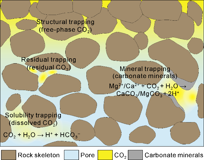
Fig. 3. Microscopic schematic diagram of formation CO2 storage mechanism. |
2.3.2. CO2 storaged geological body
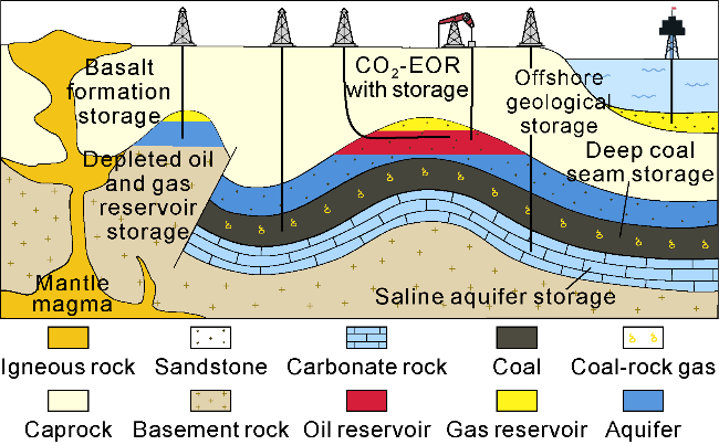
Geological site selection is the foundational step in CO2 storage projects. A suitable geological formation must simultaneously possess excellent reservoir properties, and reliable sealing capacity, and ensure environmental safety and economic viability. Currently, the primary types of geological formations considered suitable for CO2 storage include: Depleted Oil and Gas Reservoirs, Deep Saline Aquifers, Deep Coal Seams, and Basalt Formations, and Sub-seabed Geological Formations (Fig. 4).
Fig. 4. Geological storage of CO2. |
Depleted oil and gas reservoirs, among the earliest geological formations proposed for CO2 storage, rely on mechanisms including physical storage within pore spaces, capillary trapping, containment by overlying low-permeability caprocks to prevent CO2 migration, and dissolution of CO2 into formation fluids. These reservoirs offer distinct advantages: their geological structure is well-defined, the sealing integrity of the caprock is proven, extensive pre-existing well infrastructure is available, and detailed historical production data exists, all of which substantially reduce uncertainties in the storage process. Internationally, projects like Canadian Weyburn, which has cumulatively injected over 35 million tons of CO2 over more than two decades, demonstrate the economic and secure storage potential of such sites [104]. Similarly, the Australian Otway project, an early representative of onshore, multi-layer CO2 storage, injects CO2 into a depleted sandstone gas reservoir at depths of 1 500 m to 2 000 m and is currently in its third operational phase [105]. In China, the estimated storage capacity in proven oil reservoirs is approximately 20 billion tons, with an additional 15 billion tons in proven gas reservoirs [44,106], primarily located in the Songliao, Sichuan, Bohai Bay, and Ordos Basins. This significant capacity presents a strategic opportunity to repurpose these reservoirs into dedicated CO2 storage sites at the end of their productive life.
Saline aquifer storage involves injecting CO2 into deep, high-salinity, pressurized water-bearing rock formations, where CO2 is fixed through a combination of physical trapping (e.g., structural and residual/capillary trapping) and chemical trapping (e.g., dissolution and eventual mineralization). This approach offers significant advantages such as widespread global distribution, immense storage capacity, far exceeding the combined potential of all other geological storage options, and typically greater geographical isolation from human activity zones. A prime example is Norwegian Sleipner project, the global first commercial-scale storage operation, which has been injecting CO2 separated from natural gas production into a saline aquifer approximately 1 000 m beneath the seabed [16]. Other notable projects include Norwegian Snøhvit, Canadian Quest, and Algerian Salah. Unlike storage in depleted hydrocarbon reservoirs, saline aquifer storage is not dependent on the presence of prior oil or gas resources. This allows for more flexible deployment near major emission sources, facilitating the development of regional CCUS hub-and-cluster networks, which can substantially reduce the overall cost of emission abatement [107]. In China, the estimated storage capacity in saline aquifers ranges from 0.16 to 2.42 trillion tons [106], with key demonstration projects already underway in the Ordos Basin and the Songliao Basin.
Deep coal seams serve as another geological storage site for CO2. The primary storage mechanism is the adsorption of CO2 molecules onto the vast internal surface area within the microporous coal matrix. This approach offers a dual-function capability, achieving long-term CO2 sequestration while simultaneously enhancing the recovery of coalbed methane (ECBM) through the displacement of adsorbed methane by CO2. The San Juan Basin in the United States is a prominent example of a region that has achieved success in this field. It accounts for approximately 50% of the total CBM production in the nation, demonstrating the successful linkage between CO2 storage and methane recovery [108]. In China, related field practices have been initiated in multiple blocks, including the Qinshui Basin and the eastern margin of the Ordos Basin, where preliminary experience in ECBM technology and engineering has been accumulated. Furthermore, cavities created by processes like underground coal gasification or in-situ pyrolysis can also provide subsurface space for CO2 storage. This integrated “gasification-sequestration” model may emerge as a significant direction for the future development and utilization of deep coal resources.
Mafic igneous rocks represented by basalt formations have gained significant attention in recent years as a distinctive geological medium for carbon mineralization and storage. The process involves injected CO2 dissolving into formation water to form carbonic acid, which subsequently reacts with calcium and magnesium ions from silicate minerals within the basalt (e.g., olivine, pyroxene) to precipitate stable carbonate minerals such as calcite (CaCO3) and magnesite (MgCO3), achieving secure, permanent sequestration. Theoretical estimates suggest that globally, silicate minerals have the potential to store over 100 trillion tons of CO2 through this mineralization pathway [109]. Compared to saline aquifer storage or CO2-EOR, the current annual storage scale of this technology is limited due to the specific and sometimes restricted distribution of reactive basalt layers. However, successful pilot projects have validated its technical feasibility. The CarbFix project in Iceland is a pioneering example, where CO2 dissolved in water was injected into basaltic rock at depths of 400 m to 800 m. The project demonstrated that over 95% of the injected CO2 was converted into solid carbonate minerals within two years, achieving an exceptionally high mineralization rate [19]. In China, regions such as Hainan Island, the southeastern coastal areas, and parts of the northeast possess suitable geological conditions for basalt storage. Research focused on site selection and reaction mechanisms is currently progressing in these areas.
Offshore carbon storage encompasses strategies for achieving long-term carbon isolation by injecting CO2 directly or indirectly into the marine environment. The primary approaches include: (1) injecting CO2 into deep- sea sedimentary formations, where it is stored in a dense, supercritical state, contained by overlying impermeable layers and the ambient high pressure. (2) Leveraging the high-pressure, low-temperature conditions of the deep seafloor to form stable CO2 hydrates (clathrates) for solid-phase storage. (3) Injecting CO2 into natural gas hydrate reservoirs to displace methane, thereby achieving concomitant carbon storage and natural gas production. Countries such as Norway, the Netherlands, the United States, and Australia are actively pursuing marine storage demonstration projects at various scales. According to projections from the Ministry of Natural Resources of China, the storage potential in the major sedimentary basins within the maritime territory of China is estimated to be approximately 2.58 trillion tons [110], indicating that sub-seabed formations could serve as a significant storage medium for coastal regions, particularly in southeastern China. However, the large-scale implementation of offshore carbon storage carries potential risks, including seawater acidification and ecosystem disturbance. Therefore, it necessitates comprehensive multi-scale environmental risk assessments and rigorous preliminary site selection prior to deployment.
3. CCUS technological development challenges
3.1. CO2 capture
The technical pathways for CO2 capture are well-established; however, capture costs constitute 50% to 80% of the total CCUS cost, making economic viability a primary bottleneck for large-scale deployment. Key challenges include: (1) High Energy Consumption: The post-combustion chemical absorption process using amine solutions requires significant energy for solvent regeneration (typically at 100-120 °C), frequently supplied by steam. Cryogenic separation demands cooling gases below -70 °C, incurring substantial compression and refrigeration energy penalties. Direct Air Capture (DAC) systems must process over a million cubic meters of air to capture one ton of CO2, posing major challenges for mass transfer efficiency and energy consumption management. (2) Limitations of Capture Materials: Current sorbents and solvents face trade-offs in selectivity, capacity, stability, and regenerability. Many physical adsorbents suffer from competitive adsorption effects, reducing separation efficiency, and risk degradation over repeated adsorption-desorption cycles. Chemical absorbents are often limited by the number of available reactive sites, resulting in relatively low dynamic adsorption capacities. (3) Heterogeneity of Emission Sources: Industrial CO2 sources vary widely in concentration and composition. While capture from high-concentration streams (e.g., from ammonia or ethanol production) is mature, low- concentration, dilute sources present complex gas mixtures with low CO2 partial pressure. This makes technology standardization difficult and drives costs significantly higher. In the upstream oil and gas sector, for example, dispersed field locations and smaller-scale, less stable gas sources further increase transportation and infrastructure costs, compounding economic challenges.
3.2. CO2 utilization
China currently faces several key challenges in its pursuit of large-scale CO2 geological utilization. (1) Limited Access to CO2 Sources: Naturally occurring CO2 reservoirs are scarce in China, making it difficult to establish a stable natural CO2 supply system. Currently, CO2 is primarily sourced from industrial emissions (coal-fired power plants, chemical factories). The associated capture and purification costs are high. Furthermore, the often long-distance transportation required between emission sources and suitable oil and gas fields adds significant operational expenses. (2) Complex Geological Reservoir Conditions: the onshore reservoirs of China are predominantly continental sedimentary formations, which are characterized by significant heterogeneity and variable permeability. This leads to an unstable CO2 displacement front, prone to viscous fingering or channeling through high-permeability streaks, reducing sweep efficiency. Additionally, the crude oils in these reservoirs have a high content of heavy components, resulting in generally high minimum miscibility pressures (MMP), exceeding 20 MPa. This makes achieving efficient miscible displacement challenging, thereby limiting oil recovery enhancement. (3) Insufficient Infrastructure: the development of a dedicated CO2 transportation network in China is still in its early stages. The lack of a large-scale, cross-regional pipeline system is a major bottleneck for CO2 geological utilization. Moreover, existing traditional carbon-steel equipment, including pipelines, storage tanks, and compressors have insufficient acid corrosion resistance. Aging equipment in some surface facilities further complicates the challenge of ensuring the long-term, safe, and reliable operation of CO2 transport and injection systems.
CO2 chemical utilization continues to face significant technical challenges. First, conversion efficiency remains limited. Due to the inherent chemical inertness of CO2, related processes often suffer from low energy efficiency and reaction rates, typically achieving conversion rates of only 30% to 40%. This results in a large fraction of CO2 not effectively transformed into valuable chemicals, while the separation and treatment of by-products adds further complexity. Issues such as poor catalyst stability and durability, alongside the high cost of precious metal-based catalysts, further elevate the overall conversion costs. Second, the processes are highly energy-intensive. Converting CO2 into chemicals and fuels typically requires demanding conditions such as high temperature, high pressure, or high electrical potentials. Energy consumption can account for 40% to 60% of the total operational cost. Crucially, if the required electricity is still generated from fossil fuels, the indirect carbon emissions from power generation could negate or even exceed the carbon reduction benefits gained from the CO2 conversion process itself.
3.3. CO2 storage
The commercialization of carbon storage at scale faces several interrelated challenges. First, it involves high economic costs, as a complete CO2 geological storage project encompasses site characterization, transportation, injection, and the long-term operation of a high-precision monitoring system. This results in complex, capitalintensive lifecycle costs with substantial operational and maintenance expenses. Second, there is a lack of sufficient profitability drivers. Unlike CO2-EOR, which generates direct revenue, pure storage aimed at permanent sequestration offers no immediate economic return. In the absence of a well-developed carbon market, robust policy support, and effective incentives, the high upfront investment and long-term operational costs of such projects are difficult to recover through market mechanisms alone. Third, there are long-term integrity and risk management concerns. The migration and trapping behavior of CO2 within complex geological formations over centuries is challenging to predict with certainty. Corrosive interactions involving CO2 can compromise the integrity of underground pipelines, wellbores, and sealing devices. Long-term geochemical reactions between CO2, brine, and rock minerals may progressively alter reservoir porosity and permeability, potentially affecting storage security. Furthermore, the large-scale injection of CO2 could lead to secondary environmental impacts, such as acidification of shallow groundwater aquifers, raising concerns about groundwater contamination.
4. CCUS critical technology development directions
4.1. Low-concentration CO2 capture technology
The capture of low-concentration CO2 suffers from low thermodynamic efficiency, with energy consumption typically 30% to 50% higher than for capturing CO2 from conventional, more concentrated sources. Effectively addressing the widespread, dilute carbon sources present in atmospheric and similar environments is therefore critical. Developing advanced technologies to efficiently capture low-concentration CO2 represents a key technological frontier for achieving deep decarbonization across various sectors.
To advance the industrialization of low-concentration CO2 capture, a multi-faceted approach is required. (1) Developing novel, high-performance sorbent materials is crucial. This involves enhancing the cycle stability of mature amine-based systems and constructing low-energy, high-selectivity mixed-amine blends to optimize adsorption and desorption rates collaboratively. Simultaneously, designing high-performance porous adsorbents with tailored pore structures and surface chemistry can improve their capacity and stability. Furthermore, innovations in membrane materials, through polymer modification, development of novel inorganic materials, and design of mixed-matrix membranes, are needed to create systems with specific separation functions. (2) Pursuing low-energy process innovation is essential. This includes utilizing non-traditional heating sources such as solar energy to enable low-temperature desorption and milder regeneration strategies. Research into heating-free desorption pathways, such as pressure-swing processes co-optimized with specific sorbent materials, should be accelerated. Deep integration of the capture process with downstream utilization pathways can also prevent the significant energy penalties associated with multiple conversion steps. (3) Promoting distributed capture for dispersed carbon sources is critical. Developing modular capture units suitable for distributed emission sources such as small-scale industrial, agricultural, and mobile transportation would allow for flexible deployment across diverse scenarios. This technology would provide a vital complement for addressing hard-to-abate residual emissions, working in tandem with traditional CCUS to build a comprehensive carbon capture framework that spans from centralized industrial carbon sources to distributed atmospheric carbon sources.
4.2. CO2 enhanced oil recovery technology
As the most commercially viable CCUS pathway for the oil and gas industry, CO2-EOR holds the potential to achieve an annual injection scale on the order of hundreds of millions of tons in the future. Its core enabling technologies primarily include supercritical CO2 flooding, water-alternating-gas (WAG) injection, and CO2 huff-n- puff processes.
Achieving efficient oil recovery via CO2-EOR critically depends on maximizing the volumetric sweep efficiency of the injected gas. This objective can be advanced through two primary strategies. (1) Advancing Integrated Geology and Engineering: from the outset of the project, a comprehensive evaluation of reservoir conditions, including geological structure, sedimentary facies, and fluid properties, is essential. This foundation enables the selection of an optimal development strategy based on reservoir heterogeneity, fracture intensity, and gas channeling risk. Engineering parameters such as well pattern, spacing, production pressure, and gas injection rate must be rigorously optimized. Enhanced dynamic coordination between injection and production wells is crucial, involving active management of production rates through well controls (e.g., shut-ins, choke adjustments). This integrated approach effectively stabilizes the gas-oil contact, suppresses premature gas breakthrough, and ultimately expands the CO2 sweep volume. (2) Developing Novel Chemical Systems: building upon existing conformance control technologies, research must address limitations like poor thermal and salinity tolerance, gel dehydration, high cost, and environmental impact. Advanced techniques for the quantitative and precise identification of gas channeling pathways are needed. Concurrently, the development of new CO2 miscibility enhancers is a priority, including formulating blends with small hydrocarbon molecules such as BTEX and petroleum ethers, or creating sophisticated composite surfactant systems with phase-behavior-modifying capabilities. These chemical systems aim to improve CO2 capacity to extract and dissolve heavier crude oil components, thereby reducing the Minimum Miscibility Pressure (MMP) and significantly increasing the ultimate oil recovery factor.
4.3. Green fuel synthesis from CO2
The synthesis of green fuels such as methanol, methane, syngas, and high-carbon hydrocarbons from CO2 transcends the boundaries of traditional energy systems. It offers a compelling solution that simultaneously recycles carbon emissions and stores renewable energy, positioning itself as a critical pathway for building a clean energy system.
Future research in CO2-based green fuel synthesis must balance fundamental science with engineering applications. (1) Developing High-Efficiency, Stable Catalytic Systems: A primary focus is on creating catalysts that enable highly selective CO2 conversion under low-energy conditions. These catalysts should facilitate C-C and C-H bond formation under mild conditions. A deep understanding of reaction pathways and intermediate evolution is essential to precisely control product distribution and suppress unwanted side reactions. (2) Integrating with Renewable Energy Systems: Leveraging clean power sources like wind and solar to drive CO2 conversion reactions is key to enhancing the overall sustainability of the process and establishing a dual "carbon-energy" cycle. Take methanol synthesis via CO2 hydrogenation, a relatively mature route, as an example. By coupling it with green hydrogen produced via water electrolysis or solar- powered water splitting, a fully green methanol production chain (CO2-H2-CH3OH) can be realized. Methanol boasts a high energy density of approximately 4 300 kWh/m³, surpassing that of compressed natural gas and many fuel cell systems. Its advantages for storage at ambient conditions and cost-effective long-distance transport make it an excellent liquid energy carrier, effectively acting as a means to store and transport hydrogen.
4.4. Microbial conversion of CO2
The microbiological conversion of CO2 is a mild process and can yield high-value products. With the rapid advancements in synthetic biology and genetic engineering, microbial metabolic pathways can now be precisely redesigned and optimized. This capability allows for the expansion of product portfolios and the reprogramming of carbon flux distribution within cells. Consequently, this technology is paving the way for safe, sustainable, and green bio-manufacturing routes across diverse sectors such as energy, chemicals, food, and pharmaceuticals.
Future research priorities include: constructing next- generation engineered microbial cell factories to optimize key enzymes in the carbon fixation and conversion pathways of CO2-fixing strains, thereby enhancing CO2 assimilation and fixation rates; screening and engineering carbon-fixing algal strains tolerant to high CO2 concentrations, developing integrated technologies for large-scale microalgae cultivation coupled with industrial flue gas capture, and producing high-value products such as biofuels, biodegradable polymers, and chemical precursors; and expanding the environmental adaptability of CO2 biological utilization by exploring the carbon fixation and conversion mechanisms of extremophiles. Taking the petroleum industry as an example, the diverse oil and gas basins of China, with their wide range of reservoir types, temperature-pressure regimes, and salinity conditions, provide varied “natural bioreactor” environments for CO2 transformation and fixation. The complex and diverse microbial communities within these geological systems could be harnessed. By integrating with applications such as surface gas separation, oilfield wastewater treatment, and enhanced recovery of residual subsurface hydrocarbons, these biological processes can be effectively synergized with other CCUS components in the oil and gas sector to achieve complete CO2 conversion and sequestration.
4.5. CO2 mineralization storage synergized with hydrogen production
CO2 mineralization storage technology is regarded as one of the most ideal carbon sequestration pathways due to its immense theoretical storage capacity, high inherent safety, and relatively low long-term monitoring burden. The potential global storage volume through mineralization is projected to reach tens to hundreds of billions of tons.
To advance the engineering application of CO2 mineralization, systematic research can be focused on ground- based/subsurface carbonation and integrated carbonation-hydrogen production technologies. First, a key priority is accelerating the mineralization reaction and optimizing the process. This involves elucidating the interfacial reaction mechanisms of mineral dissolution and precipitation, developing efficient chemical catalysts to modulate the chemical environment at the water-rock interface, and promoting carbonate nucleation and growth. Enhancing the subsurface reactive environment through methods like thermal stimulation and hydraulic fracturing can significantly increase the CO2-water-rock contact area and reaction kinetics. Furthermore, integrating artificial intelligence with multi-scale reactive transport modeling enables precise prediction and dynamic control of the mineralization process. This allows for the intelligent optimization of injection parameters to maximize reaction efficiency, laying a solid foundation for large-scale deployment. Second, an exploratory direction is to research into subsurface mineralization coupled with hydrogen production. Leveraging the characteristic that the serpentinization of ultramafic rocks (e.g., peridotite) in the presence of CO2 can spontaneously reduce water to hydrogen, this approach aims to inject captured CO2 for mineralization while simultaneously stimulating subsurface hydrogen generation. Research would focus on unraveling the multi-physics coupling mechanisms between CO2 injection, mineral dissolution, and H2 formation. It would also assess the hydrogen accumulation patterns and production potential in different geological structures. The goal is to establish a complete "carbon sequestration-hydrogen production" value chain, achieving synergistic benefits between permanent carbon storage and clean energy generation.
4.6. CO2 cushion gas replacement in underground gas storage
The natural gas consumption of China continues to rise steadily and is projected to reach approximately 550 billion cubic meters by 2030. To meet this demand, the scale of Underground Gas Storage (UGS) facilities is expanding significantly. Cushion gas, which occupies a portion of the total gas volume in a storage reservoir to maintain operational pressure, typically constitutes 15% to 75% of a UGS’s total inventory. The technology of CO2 cushion gas replacement involves substituting this traditionally inert cushion gas (often methane or nitrogen) with CO2. This approach offers a promising pathway for achieving dual objectives of not only providing substantial carbon sequestration capacity on a large scale, but also supporting the critical function of natural gas peak-shaving for energy security.
Leveraging the high density, high compressibility, and favorable thermodynamic properties of CO2 as cushion gas can effectively reduce methane retention losses and lower operational costs. Key research directions for this CO2 cushion gas replacement technology in Underground Gas Storage (UGS) include: (1) Ensuring Gas Purity During Withdrawal: based on the physical property differences and mixing behavior between CO2 and methane, research must uncover the interfacial evolution and spatial distribution of the CO2 cushion during the injection/withdrawal cycles of the working gas. The goal is to prevent premature CO2 breakthrough and maintain high methane purity in the withdrawn gas, providing a theoretical basis for optimizing UGS operations and economic evaluations. (2) Assessing Long-Term Storage Integrity: it is critical to systematically evaluate the long-term impact of a static CO2 cushion on UGS structural integrity. This involves investigating potential chemical reactions between CO2 and the reservoir rock or pore fluids under high-temperature, high-pressure conditions to identify any leakage risks induced by dissolution or other geochemical processes, thereby ensuring long-term containment security and stability. Concurrently, research should advance the applicability of this technology to different UGS types (salt caverns, depleted hydrocarbon reservoirs) to explore the feasibility of industrial-scale implementation where CO2 replaces traditional natural gas as the cushion medium.
5. CCUS development strategy and countermeasures of China
(1) Achieving breakthroughs in low-cost technologies. The current maturity levels vary across different CCUS segments. To address this, it is crucial to move beyond the siloed development of individual technologies. Key priorities include optimizing source-sink matching, integrating energy and material flows, and coordinating the development of CO2 transport networks and storage infrastructure. Leveraging economies of scale and clustering effects will be essential to reduce the energy demand and operational costs across the CCUS value chain, thereby establishing a sustainable economic cycle. Technological innovation remains central to comprehensive cost control. This involves focused R&D on low-cost capture technologies through advancements in sorbent materials and separation processes. Simultaneously, increased investment is needed for large-scale subsurface CCUS applications, such as CO2-EOR and saline aquifer storage. By fully unlocking the utilization value of carbon resources and transforming CO2 from a waste product into high-value products, the revenue generated can help offset processing costs and improve overall project economics.
(2) Developing regional pipeline networks and cluster-based layouts. Drawing extensively on the experience of constructing natural gas transmission and distribution networks, priority should be given to planning CO2 trunk pipelines and regional hubs to enhance economies of scale in transportation, reduce expansion costs, and establish a seamless “source-hub-storage site” pipeline network. Comprehensive factors such as regional industrial structure, carbon emission density, and geological conditions should guide the prioritization of cluster-based development models. Key focus areas (e.g., Northeast China, the Bohai Rim, Western China, and the Yangtze River Delta) and key industries (e.g., oil & gas, power generation, steel, cement, and chemicals) should be identified. By leveraging localized pipeline networks, multiple industrial emission sources can share carbon capture, transportation, and storage infrastructure. This approach lowers unit costs, improves operational efficiency, and fosters the establishment of regional carbon management ecosystems.
(3) Flexible technology integration based on regional and sectoral differences. An adjustable CCUS technology portfolio should be constructed according to regional resource endowments and industrial characteristics. In the industrial-dense eastern coastal regions, the focus should be on developing the “industrial point-source capture + offshore geological storage” model. In the energy-rich western regions, abundant renewable wind and solar resources should be leveraged to establish an “integrated western wind and solar-based hydrogen/ammonia+CCUS” model, creating a coupled system for “new energy conversion-chemical production-carbon storage/ utilization”. For different industrial sectors: the power generation sector can explore “pre-combustion/ post-combustion hybrid capture,” while the chemical industry should advance “high-concentration carbon source capture +chemical utilization”. Concurrently, supporting infrastructure such as modular CO2 transmission pipeline networks and intelligent dispatch platforms should be developed. These systems will optimize CO2 source-sink matching, enable real-time adjustment of capture, transportation, and storage loads, and ultimately achieve optimal cross-regional and cross-sectoral carbon-source matching.
(4) Dual-driven by policy regulation and market mechanisms. At the policy level, there is a need to accelerate the improvement of the carbon market framework by establishing a clear carbon pricing mechanism, defining models for carbon taxes and emissions trading, and clarifying carbon emission accounting methodologies for CCUS projects. For non-compliant enterprises, a tiered carbon tax could be levied, while supportive measures such as tax incentives should be provided to energy companies investing in CCUS. Globally, efforts should be made to strengthen standards alignment with other nations. While enhancing domestic carbon trading systems, it is essential to establish frameworks for cross-border investment in CCUS projects and mutual recognition of carbon credits, thereby lowering the barriers to technology dissemination. Concurrently, exploring differentiated carbon tax policies and improving the global carbon pricing network are crucial. Integrating CCUS into the international carbon market trading framework, and establishing carbon pricing partnerships within the Belt and Road Initiative through technology exports and carbon market connectivity, can effectively promote CCUS applications in developing countries.
(5) Cross-disciplinary innovation and cross-industry collaboration. The diverse technological demands and application scenarios of CCUS require a systematic transformation from “technology demonstration” to “large-scale application,” which hinges on cross-disciplinary integration and cross-sectoral coordination. As the field spans multiple disciplines, including chemistry, materials science, geology, environmental science, and energy engineering, there is an urgent need to pool research strengths from various directions to conduct systemic investigations. This requires breaking down knowledge barriers between disciplines and expanding pathways for CCUS to synergize with other low-carbon technologies. Furthermore, collaboration across industries, such as new energy, construction, agriculture, and food production, can provide new value growth opportunities for CCUS. Establishing a cross-industry CCUS alliance would help formulate scenario-specific technical standards, carbon accounting methods, and certification norms, ultimately constructing comprehensive low-carbon economy solutions.
6. Conclusions
The CCUS technologies of China continue to advance, with efficiency improving across key components. However, the sector has yet to achieve stable economic returns, facing core challenges such as uneven development across technological segments, a lack of economies of scale, and limited advancement in carbon pricing policies. There remains significant scope for breakthroughs in reducing the energy consumption and cost of capture, expanding the sweep efficiency of geological utilization, improving the catalytic system efficiency for chemical conversion, and ensuring the long-term safety and stability of geological storage. Looking forward, as a critical “last-resort” technology for achieving carbon neutrality, CCUS is poised to develop a new paradigm characterized by scale, clustering, networked infrastructure, green processes, and diversification. This evolution involves deep integration with traditional fossil fuel systems such as coal power, chemicals, and petroleum to enable profound decarbonization, while also converging with new energy systems, such as wind, solar, hydrogen, and biomass, to facilitate carbon resource circularity. Through optimized technology portfolios and integrated innovation, CCUS will support the deep integration and continuous upgrading of the CO2 value chain.
To accelerate this progress, it is essential to implement targeted subsidies and regulatory standards to strengthen high-level policy guidance, increase investment in CCUS infrastructure to build industrial clusters in key regions; and foster cross-disciplinary, cross-industry collaborative innovation. By advancing new materials, equipment, and processes, novel decarbonization solutions can be developed for multiple sectors. The goal is to progressively scale CCUS deployment from million-ton to ten-million- ton and eventually billion-ton levels, establishing a comprehensive technological and industrial demonstration system that progresses from low-carbon to zero-carbon and ultimately to negative-carbon pathways. This will provide robust technological, systemic, and policy foundations to empower CCUS in supporting the goal of carbon neutrality of China.