


Introduction
Separated-layer water injection and commingled oil production is commonly adopted in oilfields of China. With the progress of oilfield development, the injection side is increasingly subdivided and intelligent, while the production end is still commingled. Over years of operations, interlayer and planar contradictions result in uneven production profile and poor recovery of low-permeability reservoirs. When waterflooding is implemented, reservoir heterogeneity causes water breakthrough in high-permeability layer, resulting in the rise of water cut of produced fluid, the change of reservoir physical properties, the increase of interlayer difference, and the increasingly complex oil-water distribution [1⇓⇓-4]. In the late development stage of a high water-cut old oilfield, it is of great significance to accurately obtain the development performance data (e.g. pressure and fluid parameters) of each oil layer. On one hand, this can provide an important basis for the adjustment and optimization of development plan and the implementation of EOR measures such as reservoir stimulation, so that the rise of water cut in production wells can be controlled and various oil layers can be recovered in a balanced manner, thereby improving the level of oilfield development. On the other hand, well intelligentization is an important part of the intelligent injection-production system, and the data is the basis of well intelligentization. If diverse and accurate production data, such as zonal pressure, fluid property, fluid production profile and permeability, are measured or determined from measured parameters, the intelligent reservoir analysis model can be more precise and refined, facilitating the intelligent adjustment and optimization of development plan to realize intelligent injection and production.
The integrated sampling and pressure testing technology is mainly used in drilling and production stages. Oilfield service companies in China and abroad have developed a series of wireline formation testing and sampling technologies [5⇓-7]. However, these technologies are mostly suitable for big holes and open holes and for formation testing while drilling, but not applicable to 139.7 mm (5.5") cased holes at the production stage in China. For the production stage, the cable-conveyed zonal sampling and pressure testing technology [8⇓⇓⇓-12] and the pipe string-carried preset zonal sampling and pressure testing technology [13-14] have been formed. Similar to the cable-through formation testing technology overseas, the sampling test realizes testing by isolating the test layer; however, it is deficient due to limited isolating thickness of the packer, complex system structure, low reliability and difficult maintenance. The pressure test is disadvantageous for multiple operations, cumbersome procedures, long well occupation and unknown and uncontrollable downhole conditions.
As to sampling and pressure testing for production wells, different techniques are commonly used. Zonal pressure buildup test includes conventional mechanical string zonal pressure test [15] and annulus-through zonal pressure test [16-17]. The former is realized by moving the string after the well production is stopped and needs drifting, flushing and sand washing before testing, which may seriously affect the test accuracy. Moreover, during the test, the packer is inflated, and the memory type electronic pressure gauge is used to test the layer pressure; thus, the test success rate is sensitive to the inflation effect of the packer. As to the latter, the zonal pressure test string is run first; then, the well production is resumed, and the pressure gauge is landed from the annulus to measure the pressure of the target interval once the test sealing section is accurately connected with the sealing section of the string. Its effect is sensitive to many factors such as connecting position, cup packing of the pressure gauge and the sealing of the pressure test string. In general, these pressure testing techniques suffer from problems like limited application conditions, cumbersome process, low efficiency, long well occupation and high cost. Downhole fluid sampling is rarely conducted in wells with consideration to technical difficulty, operation success rate and cost. Instead, fluid mixture from the borehole is often sampled at the wellhead, and the single-layer fluid cannot be obtained accurately.
This paper presents a modular zonal sampling and testing technology for production well to accurately obtain reservoir pressure and fluid parameters, which has the characteristics of modularization, full electronic control and rapidity. A series of laboratory and field tests have been carried out.
1. Testing principle and system framework
1.1. Testing principle and system function
Liquid in a wellbore under commingled oil production is the mixture of liquids produced from multiple perforated intervals. In order to obtain the formation fluid sample and pressure buildup curve of a single interval, the interval to be tested is isolated into an independent unit, and then the fluid mixture between the packers is displaced to make the formation fluid inflow. When the fluid mixture between the packers is completely displaced, sampling is initiated. In this way, the real formation fluid sample of a single interval is obtained. Meanwhile, pressure buildup test can be performed on single layer in a specific time if necessary for oilfield production. Obviously, the downhole zonal sampling and testing system should include the basic functional modules such as packer, drainer, and sampling and testing device, allowing the system to be capable of isolating, drainage, sampling and pressure testing, as shown in Fig. 1. To ensure the reliable operation of the functional modules and the accurate positioning of the packer unit, the system should also be configured with anchor and downhole depth positioner depending on well conditions. In theory, if multiple packers and sampling & pressure testing devices are installed, and the distance between packers is adjusted according to the depth of each oil layer, the sampling and pressure testing of multiple layers (Fig. 1) can be realized simultaneously.
Fig. 1.
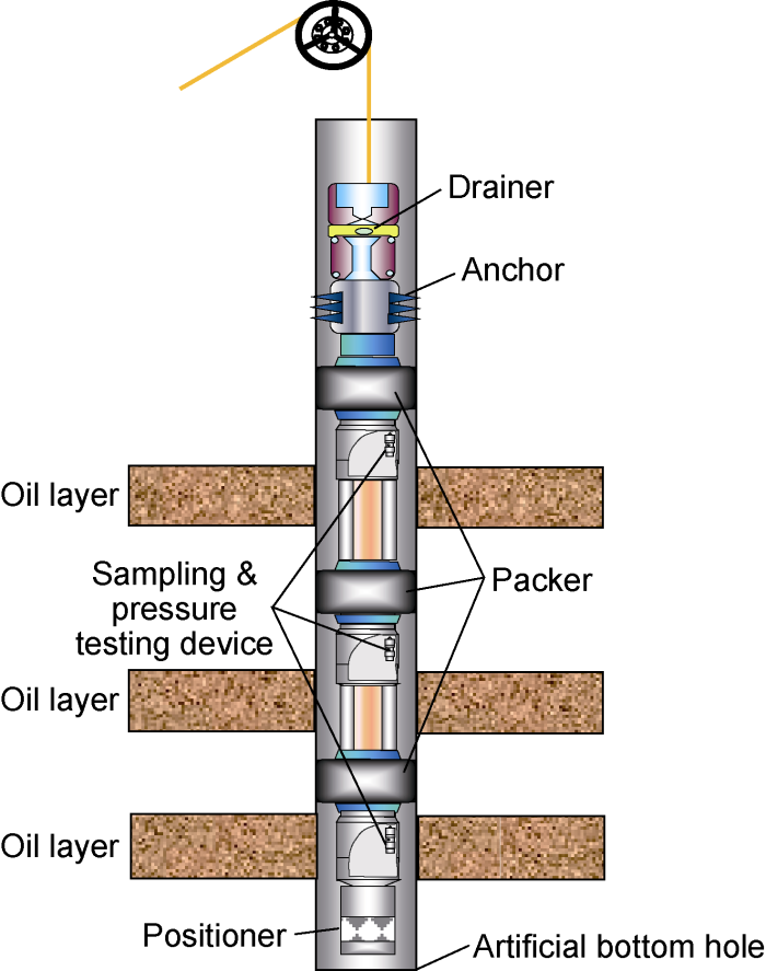
Fig. 1.
Principle of the zonal sampling and testing system.
1.2. System framework
Based on the above principle, a modular zonal sampling and testing (MST) system is designed, which includes the functional modules such as downhole power supply module, drainage pump, electronically controlled anchor, electronically controlled packer, electronically controlled sampler, magnetic positioning sub, terminal sub, adapter cable and quick connector, as shown in Fig. 2. The ground control system supplies power to the tool string of the downhole functional module through cables, and keeps data communication with the downhole functional module by bus. The downhole power supply module completes the voltage transformation to meet the high-power drive and low-power supply requirements of all downhole functional modules. The drainage pump discharges the liquid between the packers and near the wellbore to the upper part of the upper packer. The electronically controlled anchor fixes the whole tool string on the casing to avoid the creeping up and down of the tool string during the operation, and improve the setting effect of the packer and the reliability of the system. The electronically controlled packer is set to isolate the interval to be tested. The magnetic positioning sub realizes the positioning of the string and tool in the process of run in hole (RIH), so as to ensure that the packer accurately isolates the interval to be tested. The terminal sub realizes communication matching and adjustment under different depth. The adapter cables have different specifications, and can adjust the packer spacing according to the reservoir thickness. In this system, the minimum packer spacing is 1.8 m, and the maximum packer spacing is unlimited. The quick connector mainly realizes the fast and reliable mechanical, electrical and liquid channel connection among the modules.
Fig. 2.
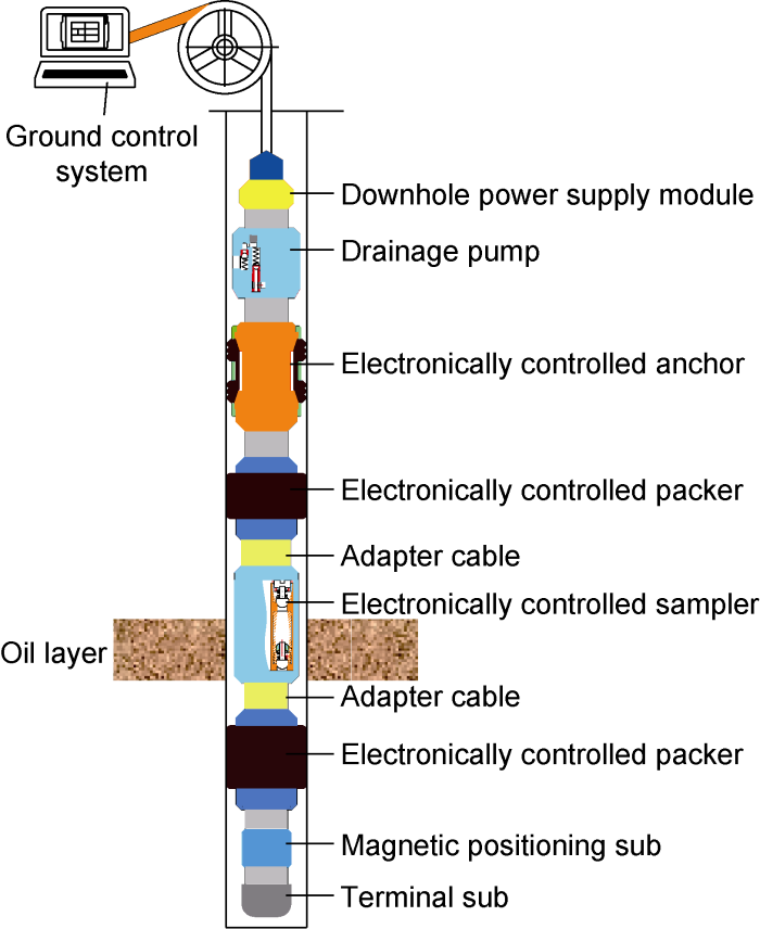
Fig. 2.
Composition of the MST system.
The MST system involves multiple complex functional modules, each of which is difficult to develop. The integration of multiple modules is much more difficult technically, and it raises high requirements for the reliability and stability of the modules. For purpose of reliable and successful downhole operation, the sampling and testing are conducted by isolating one layer each time. The sampling and testing of up to 3 layers can be realized in a single RIH, because the sampler is equipped with 3 sampling cylinders.
The MST system has the following characteristics:
(1) Fully electronically controlled. The MST system adopts full electronic drive and control mode to ensure the stable and reliable operation of downhole tools. Compared with the traditional downhole control tools, it has the advantages of simple structure, convenient control and high reliability. In traditional downhole tools, packers and anchors are usually electro-hydraulically driven. Although such a design is favorable for low-power drive and high torque output, the use of hydraulic systems makes the system extremely complex and makes the design of downhole tools very difficult in confined downhole spaces.
(2) Modularization. The MST system adopts unified mechanical interface standard, ground and downhole power supply standard and bus communication protocol. The functional modules are independent and do not affect each other. The system function can be arbitrarily combined depending on the site conditions, and the position of the functional module can be adjusted, which is beneficial to the system reliability and the field operation success rate. When a module in the system fails or needs maintenance after use, it only needs to be replaced or directly removed without affecting the system integrity and the normal operation of other modules. Moreover, any new functional module meeting the above standards can be easily integrated into the system. Thus, the system is highly scalable.
(3) Rapidity. The downhole functional modules of the MST system are capable of both passing liquid and passing cables. They are designed with customized internal configuration and uniform interface at both ends. Liquid can pass through the center of the end faces, while cable can pass through the annulus. During on-site construction, just by plugging the cable connector and tightening the mechanical structure can realize the rapid integration of mechanical, electrical and liquid channels. Thus, the field operation is simplified. It takes only a few minutes to complete the connection of downhole functional modules. This improves the system reliability, stability and efficiency, and also reduces the well occupying time and the influence on normal production.
2. Preproduction and laboratory test of core tools
Based on the testing principle and the system framework structure, six types of downhole tools (power supply module, electronically controlled drainage pump, electronically controlled anchor, electronically controlled sampler, electronically controlled packer, and magnetic positioning & terminal sub) and ground control system were independently designed and preproduced, as shown in Fig. 3.
Fig. 3.
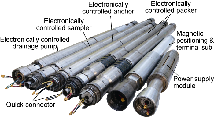
Fig. 3.
Downhole tools in the MST system.
Temperature/pressure resistance tests and functional tests (including packer setting/releasing, anchoring, and opening/closing of sampling cylinder) were conducted on the downhole functional modules under simulated conditions closest to field conditions, in order to check the performance, stability and reliability of the tools in the MST system. The laboratory test environment is shown in Fig. 4, where the test well and the tension-compression test machine are equipped. The test well is mainly used for the overall temperature/pressure resistance test and the functional test under the temperature and pressure environment of a single tool (Fig. 4a), and the tension-compression test machine is mainly used for the forced freeing test of the electronically controlled anchor under anchoring state (Fig. 4b). The wellbore volume of the test well is 29 L, the working fluid is water or oil, and the test temperature ranges from the room temperature to 180 °C. Each test well has 2 pressurizing channels: upper and lower parts, with a rated pressure of 0-105 MPa, which are qualified for pressure and temperature resistance test of downhole modules and differential pressure test of packer rubber. The tension-compression test machine can resist a tension of 0-200 kN, meeting the test requirements of anchor and safety device.
Fig. 4.

Fig. 4.
Laboratory test environment of downhole functional modules.
2.1. Preproduction and test of electronically controlled packer
As shown in Fig. 5, the electronically controlled packer is mainly composed of control circuit, motor, drive mechanism, packer rubber and liquid channel. When the packer is set, the motor drives the guide screw to rotate clockwise, allowing the packer rubber shaft to move rightwards and compress the packer rubber to inflate. When the packer is released, the motor drives the guide screw to rotate counterclockwise, allowing the nut packer rubber shaft to move leftwards and release the packer rubber. The electronically controlled packer is designed with a no-go sensor, which can automatically judge the setting/releasing state during the test, in order to improve the reliability of the packer.
Fig. 5.
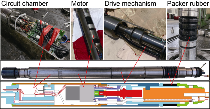
Fig. 5.
Schematic structure and photos of components of the electronically controlled packer.
According to the drive mechanism of the packer, when the packer is set, the driving moment Mq is the sum of the friction moment of thread Mt1, the friction moment of the screw-driven axial support surface Mt2 and the friction moment of the screw-driven radial bearing Mt3[18], expressed as:
Since there is no radial support for the driving mechanism of the electronically controlled packer, Mt3 is 0. Substituting Mt1 and Mt2 into Eq. (1), we have
where
It is derived that λ is 1.71° and
For purpose of liquid discharge, the electronically controlled packer is designed with a liquid channel with an equivalent drift diameter of 12 mm, which can allow the passing of liquid without obvious choke pressure difference. Meanwhile, the packer has 3 pressure sensors with a range of 35 MPa and a precision of ±0.5%, which can simultaneously monitor the pressure of the upper annulus, the lower annulus and the central channel of the packer rubber. The upper and lower pressure sensors of the packer rubber allow the electronically controlled packer to make self-test of setting/releasing. In field test, if the packer is well set, a difference appears between the upper and lower pressures of the packer rubber due to the change of formation pressure, by which the packer setting status can be judged. When the upper and lower packers are well set, the lower pressure sensor of the packer rubber of the upper packer and the upper pressure sensor of the packer rubber of the lower packer can simultaneously measure the pressure of the formation. Thus, the formation pressure can be measured by recording the pressure buildup curve, and also the two pressure sensors can be calibrated with each other, which greatly improve the precision and accuracy of the data. Moreover, according to the position of the electronically controlled packer in the MST system, the pressure sensor in the central channel can be used to measure the liquid level height or the fluid suction end pressure of the drainage pump.
To ensure that the packer can reliably isolate the oil layer in downhole, ground test and pressurized test of test well were conducted on the packer rubber for its differential pressure resistance. After being set on the ground, the packer was pressurized, and the pressure difference between the upper and lower parts of the packer rubber that the packer can bear is 15 MPa. Pressurized test was also carried out in the test well, with the pressure test curve shown in Fig. 6. It can be seen that the pressure difference between the upper and lower parts of the packer rubber is not less than 12 MPa, and the upper or lower high pressure can be well kept (the slow decrease of the pressure in Fig. 6 is caused by the insufficient pressure stabilizing capacity of the testing system), indicating that the sealing effect of the packer rubber is good. In addition, the pressure resistance test at 35 MPa and temperature resistance test at 85 °C of the packer, the differential pressure resistance test for 48 h of the packer rubber, and the packer setting/releasing test under certain pressure were carried out, which all confirmed that the packer has good sealing effect. In summary, the packer can withstand a pressure difference of no less than 10 MPa on the rubber cylinder after setting, and is applicable under a temperature less than 85 °C and a pressure less than 35 MPa.
Fig. 6.
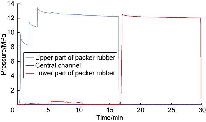
Fig. 6.
Differential pressure resistance test curve of the electronically controlled packer.
2.2. Preproduction and test of electronically controlled anchor
Structurally similar to the electronically controlled packer, the electronically controlled anchor is mainly composed of a control circuit, a motor, a drive mechanism and slips (Fig. 7). At the time of anchoring, the motor drives the guide screw to rotate clockwise, allowing the nut to move rightwards and inflate the slip to realize anchoring. When the motor drives the guide screw to rotate counterclockwise, the nut slip cover moves leftwards, and the slip retracts to realize freeing. The electronically controlled anchor is designed with a safe freeing structure for the exceptional situation that the anchor cannot be freed on site. If normal freeing is impossible, the shear pin can be forcibly nipped off to realize freeing. According to field operation experience, the shear force of the safe shear pin is set at 60-80 kN.
Fig. 7.
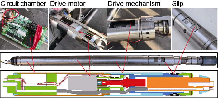
Fig. 7.
Schematic structure and photos of components of the electronically controlled anchor.
The temperature and pressure resistance tests of the anchor were carried out. When the test well was pressurized to 35 MPa and heated to 85 °C, the anchor functioned normally. The anchoring test and forced freeing test were carried out on the test well in Fig. 4, showing that the anchor can work normally. The tension-compression test machine was used to forcibly pull out the anchor. When the forced tension reached 69.8 kN, the safe shear pin of the anchor was nipped off, the slip was freed, and the anchor was successfully pulled out of the test well. As the total weight of the downhole functional modules in the MST system is less than 1 t, the above tests show that the anchor can realize the normal anchoring of the whole tool string, and also ensure the forced freeing in unexpected situations.
2.3. Preproduction and test of electronically controlled drainage pump
The electronically controlled drainage pump, with a multi-plunger structure, is mainly composed of a drive circuit, a drive motor, a plunger and a check valve (Fig. 8). The motor drives the cylinder to rotate, and the plunger reciprocates under the action of the swashplate to realize liquid suction and discharge. The drainage pump is simple in structure, compact and operable. The electronically controlled drainage pump does not have high requirements for the position of the fluid suction end, so it is more flexible in the arrangement position of the sampling and testing tool string.
Fig. 8.
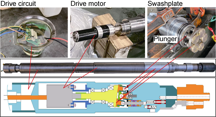
Fig. 8.
Schematic structure and photos of components of the electronically controlled drainage pump.
The temperature and pressure resistance tests were conducted on the drainage pump at 35 MPa and 85 °C, with the testing device shown in Fig. 9. The liquid supply end with a certain pressure was set for the drainage pump to ensure sufficient liquid supply. The check valve was set at the liquid discharge end, and adjusted to form pressure difference between the liquid discharge end and the liquid supply end to test the liquid discharge capacity under different pressures. The test results show that the displacement and head of the drainage pump are 0.8 m3/d and 500 m, which can basically meet the requirements of liquid discharge in wellbore and near wellbore zone.
Fig. 9.
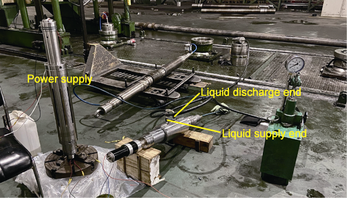
Fig. 9.
Laboratory test of electronically controlled drainage pump.
2.4. Preproduction and test of electronically controlled sampler
The electronically controlled sampler is mainly composed of control circuit, motor, drive mechanism and one-way sampling cylinder (Fig. 10). The sampler is designed with 3 sampling cylinders with a volume of 500 mL individually and 1.5 L totally. The 3 sampling cylinders are arranged in parallel. When the liquid flows from the formation into the liquid inlet end of the sampler, any sampling cylinder can be opened depending on field conditions. Under the action of formation pressure, the check valve of the sampling cylinder is opened, and then the liquid flows into the central channel of the tool string through the sampling cylinder and enters the suction end of the drainage pump. The annular fluid volume (V) between the 2 packers is calculated. According to the displacement of the drainage pump, when the displaced volume is greater than 2V, it is considered that the real formation fluid flows into the sampling cylinder, and the valve of the sampling cylinder is closed to complete the sampling of a single sampling cylinder. If multiple samples are needed, repeat the above operation, and use the remaining sampling cylinders to take samples. Check valves are designed at the inlet and outlet ends of the sampling cylinder to ensure that the formation fluid does not leak. When the sampler is lifted to the ground, the sampling cylinder can be removed from the sampler alone to complete sample transfer.
Fig. 10.
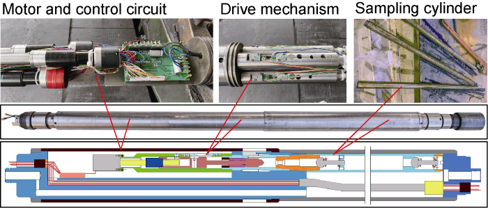
Fig. 10.
Schematic structure and components of the electronically controlled sampler.
In field test, for reducing the influence of contamination inside the sampling cylinder on the real formation fluid, the electronically controlled sampler should be run into the hole when the sampling cylinders are closed. When the sampler reaches the target horizon, the sampling cylinder is internally under normal pressure and externally under high pressure produced by the liquid column. At this time, the normal opening of the sampling cylinder under high differential pressure decides the success of sampling. Therefore, the sampling cylinder was tested for opening/closing under certain pressure. The sampler was landed into the test well, with one end connected with the test well and the other end connected with the external atmosphere. The test results are shown in Fig. 11. When the sampling cylinder is closed, the well is pressurized to about 15.5 MPa and 8.6 MPa respectively, and the pressures are stable (the slow decrease of pressure in Fig. 11 is caused by the insufficient pressure stabilization ability of the testing system), indicating that the sampling cylinder can maintain a good sealing. Then, the sampling cylinder is opened, and the pressure of the test well is instantly relieved to the normal level, indicating that the sampling cylinder is opened successfully and connected with the external environment. This suggests that the sampler can work normally under the high differential pressure. The test results show that the sampler can withstand 35 MPa pressure and 85 °C temperature.
Fig. 11.
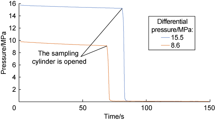
Fig. 11.
Opening/closing test curve of the sampling cylinder under high differential pressure.
2.5. Control system
The control system includes ground and downhole parts (Fig. 12), which are connected by a logging truck through 4-core armored cable: 2 cores for power supply and 2 cores for communication. For the ground part, with the reinforced industrial laptop as the core, the voltage regulation module is used to regulate and convert the external power supply voltage for downhole equipment. The bus communication card is adopted to convert and modularize the communication signals for purpose of long-distance downhole communication. The monitoring interface is used for real-time display of data and remote control of downhole tools.
Fig. 12.
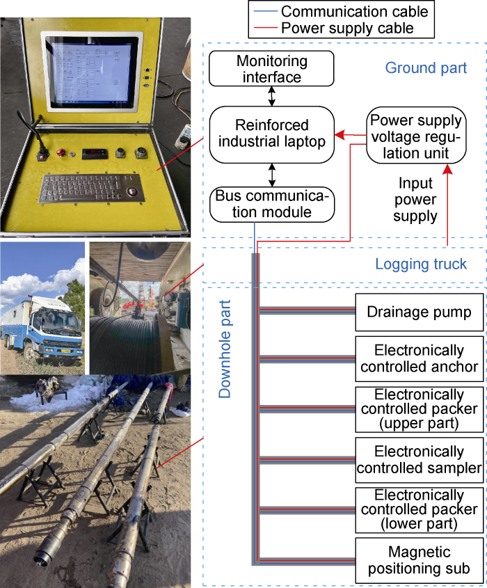
Fig. 12.
Framework and photos of the control system.
The downhole part is composed of the control systems of downhole functional modules, and can realize data acquisition and action execution. All tools are charged from the public power line, and the required power supply voltage is obtained after voltage transformation. All tools are connected to the public communication line, and two-way communication is realized through the bus. The control system in each functional module has been verified in the independent test of each module, and the ground control system and long-distance wireless communication have also passed the test in the ground joint debugging, confirming that the functions of data reading, instruction issuing, real-time graphics plotting and real-time data storage are all normal, ensuring the orderly control of the whole system.
3. Field test
3.1. Well condition and operation design
After laboratory test, field test was conducted using the modular zonal sampling and testing technology in Well Mu 141-99 of Xinmu Oil Production Plant of Jilin Oilfield. The well was perforated and completed in 2012, and developed by water injection. It produced oil from two layers, with the top boundary of 666.8 m and 687.0 m, respectively, the perforated thickness of 4 m and 5 m respectively, and the permeability of 2.6×10⁻³ μm2. In the first three months of production, the liquid flow rate was 4.8 t/d, the oil flow rate was 0.2 t/d, and the composite water cut was 96.2%. To fully understand the formation and obtain the real fluid samples, the sampling and pressure testing were carried out on the upper oil layer of the well.
Depending on well conditions, the structure of the testing tool string is designed as (Fig. 13): power supply module + drainage pump + electronically controlled packer I ((665.0±0.5) m) + sampler (669.2 m) + adapter cable (671.5 m) + electronically controlled packer II ((671.8±0.5) m) + magnetic positioning sub (674.9 m). For adapting to the perforated thickness of the oil layer, an adapter cable is configured between the two packers to realize liquid passing and cable passing.
Fig. 13.
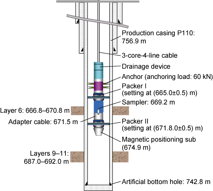
Fig. 13.
Schematic diagram of casing program and testing tool string.
During the test, the tools were connected in the bottom-up order at the wellhead, and then connected with the logging truck cable to run into the hole, and the No. 1 sampling cylinder of the electronically controlled sampler was opened synchronously to obtain the mixed fluid sample of the production well in the process of RIH. When the magnetic positioning sub detected the casing collar location, the sampler was run to the middle of the oil layer according to the casing program, then packers I and II were set to realize isolation of the oil layer, and the pressures of the two packers were used to decide their setting states. Once it was confirmed that the packers were well set, the No. 2 sampling cylinder was opened and the drainage pump was started to discharge the fluid. Since the annular volume between the two packers is about 13.5 L, the drainage pump only needed about 25 min to discharge the annular mixed fluids. In order to improve the accuracy of sampling, the No. 2 sampling cylinder was closed after continuous discharge for 1 h, and the first sample of the layer was obtained. Next, the No. 3 sampling cylinder was opened to discharge for 1 h, and then closed; the second sample of the layer was obtained.
3.2. Test process and data analysis
The pressure monitoring curve of the upper packer during sampling and testing process is shown in Fig. 14, including the pressures of the central channel and the upper and lower parts of the packer rubber. Based on pressure changes, the process can be divided into four stages.
Fig. 14.
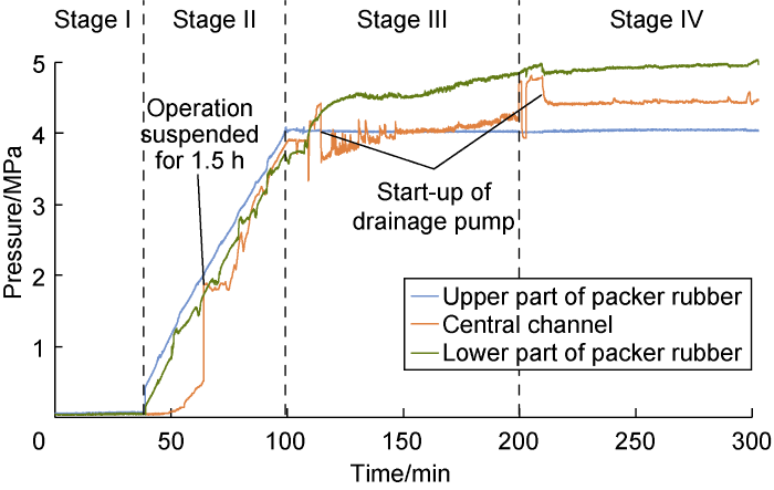
Fig. 14.
Pressure change in the process of sampling and testing.
Stage I: The pressures of the upper and lower parts of the packer rubber and the pressure of the central channel were consistent, all being normal pressures. This indicates that the testing tool did not reach the fluid level.
Stage II: The testing tool reached the fluid level at 235 m. At this time, the pressures of the upper and lower parts of the packer rubber kept consistent and rose synchronously. Since the No. 1 sampling cylinder was opened, the pressure of the central tube also rose slowly. The RIH process of the tool string was ever suspended due to power failure for about 1.5 h. In this period, the pressure of the central tube rose slowly to the fluid level pressure. Abrupt change occurred in pressure after the tool was powered on again.
Stage III: The tool went done to the target well depth, and the tool string was anchored by the electronically controlled anchor. Then, the upper and lower packers were set respectively, and the No. 1 sampling cylinder was closed to complete the sampling of mixed fluid. Subsequently, the No. 2 sampling cylinder was opened to connect with the drainage channels of annulus, formation and central tube. Next, the drainage pump was started up to discharge fluid continuously. During fluid discharge, the pressure in the lower part of the packer rubber was the formation pressure, which gradually rose from 3.93 MPa to 5.04 MPa. This slow rise indicates that the formation pressure was building up, and the lower packer was well set. Meanwhile, the pressure in the upper part of packer rubber remained at about 3.76 MPa, that is, a certain pressure difference was always maintained between the upper and lower parts of the packer rubber. This indicates that the upper packer was well set. After start-up of the drainage pump, the pressure in the central tube dropped, indicating that the drainage pump worked normally. Later, the pressure in the central tube slowly rose with the formation pressure build-up, in a trend consistent with the recovery of formation pressure. After the drainage pump continuously discharged fluid for 1 h, the No. 2 sampling cylinder was closed to complete the sampling of formation fluid.
Stage IV: The No. 3 sampling cylinder was opened, and the drainage pump was started again. After 1 h, the No. 3 sampling cylinder was closed to complete the sampling of formation fluid.
After sampling, two packers were released, and the anchor was released. Then, the tool string was lifted out of wellbore. Thus, all operations were completed. After sample transfer on the ground, 3 cylinders of fluid samples were obtained (Table 1). The fluid in No.1 sampling cylinder is the mixed sample of floating oil in the upper part and water in the lower part of the wellbore, with a water cut of 68.92%. The fluid in No. 2 sampling cylinder is the formation fluid sample after fluid discharge for 1 h, with a water cut of 93.47%. The fluid in No. 3 sampling cylinder is the formation fluid sample after fluid discharge for 2 h, with a water cut of 97.85%. The water cut difference between No. 2 and No. 3 fluid samples is 4.38%, indicating that new fluid flows into the sampling cylinder from the formation after No. 2 sampling cylinder completed sampling and the drainage pump discharged fluid again for 1 h. This suggests that the water cut of formation fluid is uncertain. The previous composite water cut of the well tested from wellhead samples was 92.5%, which is somewhat different from the analysis results of formation fluid obtained by zonal sampling. In contrast, the fluid property of single layer can be used to describe the reservoir status more accurately. Combined with the pressure curve, it can achieve more accurate reservoir analysis and evaluation, so as to optimize the development plan.
Table 1. Analysis results of fluid samples
| Sampling cylinder | Sampling volume/mL | Oil/ mL | Water/ mL | Water cut/% | Fluid source |
|---|---|---|---|---|---|
| 1 | 370 | 115 | 255 | 68.92 | Mixed fluid in wellbore |
| 2 | 337 | 22 | 315 | 93.47 | Formation fluid after fluid discharge for 1 h |
| 3 | 233 | 5 | 228 | 97.85 | Formation fluid after fluid discharge for 2 h |
4. Conclusions
The modular zonal sampling and testing technology (MST) system is composed of core tools such as electronically controlled packer, electronically controlled anchor, electronically controlled drainage pump and electronically controlled sampler with characteristics of modularization, electronic control and rapidity. Laboratory test and field test verify the stability and reliability of the system. The system is believed to be qualified for downhole zonal sampling and pressure testing under the conditions of 10 MPa isolating differential pressure, 85 °C in temperature and 500 m dynamic fluid level. It preliminarily meets the needs of field test of production wells and provides a technique for understanding the development performance.
Based on the field test status and production test requirements, the MST system will be optimized in some aspects. (1) The structure of the drainage pump is optimized, and the power of the drive motor is greatly improved, in order to achieve a substantial increase in displacement and head, so that the small displacement drainage pump is transformed into a large displacement lifting pump. (2) The overall temperature resistance level of the system is improved from 85 °C to 125 °C. (3) The structure of packer is optimized, and the pressure difference resistance of the packer rubber and the drift diameter of the liquid channel are improved. (4) Temperature- and pressure-insulation sampler and its supporting tools are developed. The optimized system can be more applicable in light of well depth, well type and reservoir type, but also complete the liquid production profile test, inflow performance curve, oil test and production test, in addition to the existing functions such as reservoir pressure test and fluid property parameters test. Moreover, it can realize the measurement or calculation of parameters such as formation permeability and skin factor. It will play an important role in identifying the predominant channel, exploring the potential layer and understanding the damage near wellbore, and it is of great significance to the finer understanding of the production layers.
The MST system serves as a complete downhole operation platform with its multiple functional modules. It is capable of downhole isolating, anchoring and lifting, and also provides high power supply and two-way communication channel for downhole tools. Its modular structure can realize the "unlimited" series connection of functional modules, that is, the "platform +" concept. In the future, depending on field requirements, the “platform” will be configured functionally, and then integrated with different "+" functional modules, so as to realize specific downhole functions. For example, "anchor + lead mold module" can realize rapid downhole lead mold rubbing, and “electronically controlled packer + bridge plug” can realize rapid and controllable allocation of bridge plug. Therefore, the MST system is not merely a rapid downhole zonal sampling and testing tool, but also expansible for various downhole tests or operations.
Nomenclature
d2—pitch diameter of thread, set at 32 mm in this study based on packer size and mechanical design manual standard;
do, di—outer diameter and inner diameter of supporting ring surface, set as 33.5 mm and 30.5 mm, respectively;
f—friction factor, set as 0.08;
F—axial load of setting of packer rubber, generally 40-60 kN, set as 50 kN based on the design experience of traditional packer;
Mq—driving moment, N·m;
Mt1—thread friction moment, N·m;
Mt2—friction moment of screw-driven axial supporting surface, N·m;
Mt3—friction moment of screw-driven radial bearing, N·m;
S—lead, takes 3 mm;
α—tooth form angle of trapezoidal thread, 30°;
λ—lead angle, (°);
Reference
Current status and trend of separated layer water flooding in China
Development and prospect of separated zone oil production technology
DOI:10.1016/S1876-3804(20)60114-8 URL [Cited within: 1]
Quick-quantitative evaluating method of the sublayer developed conditions in the multilayered heterogeneous sandstone oilfield
Precise drilling technology for residual oil in the later stage of development of extra-high water-cut reservoir
Progresses in formation testing and subsurface fluid sampling & analysis technology
Advances and challenges in formation test and practical application
Two new methods for cased hole wireline formation test
Multisublayer sample testers
Oil-layer or gas-layer deliverability test achieved by multi-layer sampling tester
AFT technique and its applied effects
Application of separated layer pressure and sampling technique in dynamic monitoring of oilfield
Development and application of separate layer pressure testing and sampling system for high water cut wells
Study on preset oilwell zonal sampling technology and its application
Application of pipe string stratified sampling in production well
Comparison of three methods for separated layer pressure testing
Separate layer pressure testing techniques & data application in Daqing Oilfield
Separate layer pressure testing technique and data application
