Supported by the Natural Science Foundation of Heilongjiang Province of China. YQ2019E007
Abstract
To predict fracture height in hydraulic fracturing, we developed and solved a hydraulic fracture height mathematical model aiming at high stress and multi-layered complex formations based on studying the effect of plastic region generated by stress concentration at fracture tip on the growth of fracture height. Moreover, we compared the results from this model with results from two other fracture height prediction models (MFEH, FracPro) to verify the accuracy of the model. Sensitivity analysis by case computation of the model shows that the hydraulic fracture growth in ladder pattern, and the larger the fracture height, the more obvious the ladder growth pattern is. Fracture height growth is mainly influenced by the in-situ stresses. Fracture toughness of rock can prohibit the growth of fracture height to some extent. Moreover, the increase of fracturing fluid density can facilitate the propagation of the lower fracture tip.
Keywords:hydraulic fracturing
;
fracture height
;
plastic region at fracture tip
;
fracture toughness
;
multi-layered formation with high in-situ stresses
LI Yuwei, LONG Min, TANG Jizhou, CHEN Mian, FU Xiaofei. A hydraulic fracture height mathematical model considering the influence of plastic region at fracture tip. [J], 2020, 47(1): 184-195 doi:10.1016/S1876-3804(20)60017-9
Introduction
As an efficient stimulation technology, hydraulic fracturing has been widely used in various oil and gas reservoirs with remarkable achievements. However, current existing hydraulic fracture models have certain limitations in field application and are not suitable for complex wells or formations[1,2], which limits the development of hydraulic fracturing technology. The fracture height, as the input of the two-dimensional hydraulic fracture model and the output of the three- dimensional model, is an important factor affecting the accurate solution with the hydraulic fracturing model. The calculation of fracture height is regarded as a key issue in the study of hydraulic fracture models[3,4]. Especially on the technical background of large-scale fracturing for unconventional reservoirs represented by shale gas[5,6,7], how to accurately predict and control the fracture height has becomes the key deciding the success of fracturing operation. For shale reservoirs with shallow burial depth and low in-situ stresses, the existent fracture height models are highly applicable[8]. But for deep and complex formations with multiple layers and high stresses, it is often difficult to predict the hydraulic fracture height[9,10]. Therefore, a new method able to accurately calculate the hydraulic fracture height in such formations is urgently needed.
During the fracturing treatment in the multi-layered complex formation with high stresses, the fracture height growth is controlled by many factors, including the bedding interface and its corresponding shear strength, pumping pressure, fracturing fluid leak-off, the development of natural fractures, and the density and viscosity of the fracturing fluid [11,12,13,14,15,16]. Despite of a variety of factors affecting the growth of fracture height in complex formation, there existing an upper limit for the fracture height under a certain pumping pressure, i.e. the equilibrium height theory[17]. When the stress intensity factors at the upper and lower tips of the fracture are smaller than the rock toughness of the corresponding locations, the fracture tip stop growing. Otherwise, the fracture tip grows and the fracture height increases.
Since the 1970s, researchers have established many fracture models for calculating the fracture height. The fracture height prediction model proposed by Simonson et al.[18] divides the formation into three symmetrical layers for both upper and lower parts and assumes the overlying layers and the underlying layers are identical in physical properties, which is quite different from the actual strata during fracturing treatment. Thus, this model is not very practical. Ahmed[19], Newberry et al.[20] and Economides et al.[21] modified the Simonson’s model and divided the strata into three set of asymmetric upper and lower layers and assumed the overlying layers and the underlying layers had different physical properties, which makes the model more practical. Considering different petrophysical properties of different strata, Fung et al.[22] considered the different petrophysical properties of different strata and developed a fracture height model containing six layers, which assumed that the net pressure within the fracture was constant along the fracture height direction. The fracture height prediction model established by Economides et al.[23] takes the variation of the net pressure within the fracture along the height direction into account. Weng et al.[14] modified and improved the Economides’ model. Liu et al.[24-25] put forward a more rigorous model called multilayer fracture-equilibrium- height (MFEH), which can be used to calculate fracture height in the formation with arbitrary layers.
Previously developed hydraulic fracture height models do not consider the influence of the plastic region at the fracture tip during the fracture height growth. Based on previous studies, considering the influence of the plastic region at the fracture tip on fracture propagation, correcting the hydraulic fracture height, we established a new fracture height model. Our research results improve the theoretical method for solving fracture height during hydraulic fracturing and provide a theoretical basis for the calculation and prediction of fracture height in complex formation with multiple layers and high stresses.
1. The plastic zone at the fracture tip and solution of the equivalent fracture
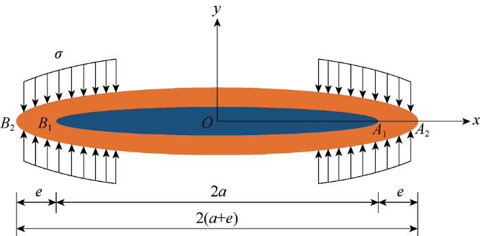
There is significant stress concentration at the fracture tip during hydraulic fracturing[26,27,28]. Under the high stress, the rock at the fracture tip changes from elastic state to plastic state. When the rock is plastic, the stress intensity factor at the fracture tip cannot be calculated with the classical fracture mechanics theoretical model because the actual fracture extension changes. As shown in Fig. 1, if the influence of stress concentration in the plastic zone at the fracture tip is not considered, the left and right end points of the fracture are A1 and B1, respectively, and the corresponding fracture height is 2a. But if the influence of stress concentration in the plastic zone at the fracture tip is considered, the left and right end points of the fracture can be extended to A2 and B2, and the corresponding fracture height is 2(a+e), showing the significant change of fracture height.
In order to further explain the influence of stress concentration in the plastic zone at the fracture tip on the fracture height, we put forward a calculation model of the plastic zone distribution at the fracture tip under plane strain condition and a calculation method of equivalent fracture height affected by the plastic zone stress in this paper. According to the theory of fracture mechanics, the stress intensity factor at the fracture tip is expressed as[30] :
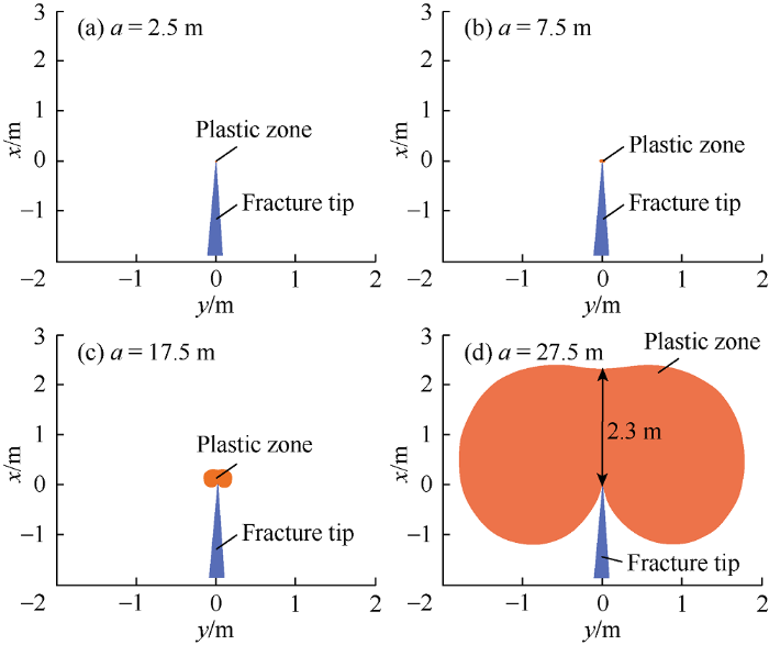
Considering the influence of the fracture height growth on the fracture tip stress intensity factor KI, the variation of the plastic zone distribution at the fracture tip was analyzed by the Eq. (4). With MATLAB programming, the plastic zone was calculated when the fracture height was set at 5, 15, 35, 55 m respectively (Fig. 2). Fig. 2 shows that the plastic zone generated at the fracture tip gradually enlarges as the fracture height increases. When the fracture height is 5 m, a tiny plastic zone is generated at the fracture tip; when the fracture height is 55 m, the height of the plastic zone is 2.3 m, which is 4.18% of the corresponding fracture height. Therefore, at the tip of fracture with different heights, there is indeed the influence brought by stress concentration to the plastic zone. When the fracture height is large, the plastic zone at the fracture tip has a large distribution range, which consequentially has a significant influence on the fracture height extension. Therefore, when calculating the fracture height, it is necessary to consider the stress concentration in the plastic zone at the fracture tip and its influence on the fracture height growth.
Fig. 2.
Distribution of plastic zone at the tip of fracture at different fracture half heights.
Dugdale[29] proposed that the fracture with the plastic zone at the tip could be replaced by an equivalent fracture, as shown in Fig. 1. The original fracture A1B1 has a height of 2a, and the equivalent fracture A2B2 has a height of 2(a+e), wherein e represents the size of plastic zone. The crack in the plastic zone is not actually opened, and the stress component at any point in the plastic zone is σy. Since the A1A2 and B1B2 segments are not fractured, the stress intensity factor at A2 and B2 of the equivalent fracture is zero. The tensile stress σy is uniformly distributed on the equivalent crack surfaces in the plastic zone, and the stress intensity factor ${K}'$produced by σy is negative because its function is to close the fracture. The absolute value of ${K}'$is equal to the stress intensity factor ${K}''$ under external load:
Eq. (9) is the plastic zone size generated in the fracture height extension direction when the stress concentration in the plastic zone is considered, i.e. the additional height generated by the fracture propagation. On this basis, the actual stress intensity factor at the fracture tip can be calculated to determine the resulting fracture height.
2. Hydraulic fracture height model
2.1. Derivation of the fracture height model
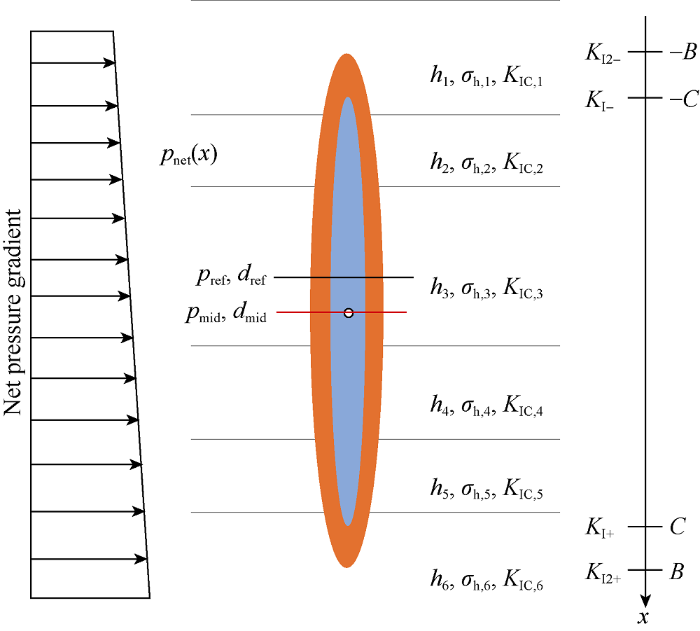
A physical model of vertical fracture height was established (Fig. 3). Fig. 3 only shows six vertical layers of different properties, but the model is not limited by the number of stratigraphic layers and can be applied to any number of layers.
Fig. 3.
The physical model of fracture vertical extension.
To establish the fracture height model, the following assumptions are made: (1) the formation rock is linear elastic medium; (2) the fluid acts on the entire fracture height; (3) the fracture extension area is far enough away from the wellbore; (4) the length of the hydraulic fracture is much larger than the fracture height; (5) the fracture height is always in equilibrium at the fracture tip; (6) the pressure distribution in the vertical direction of the fracture satisfies the hydrostatic pressure, and the pressure drop of the fluid flowing in the fracture is not considered.
When the influence of the plastic zone at the fracture tip is not considered (the blue area in Fig. 3), referring to Liu et al.[24,25] model, the stress intensity factors at the upper and lower ends of the fracture can be expressed as:
${{K}_{\text{I}-}}=\sqrt{\frac{1}{\text{ }\!\!\pi\!\!\text{ }C}}\int_{-C}^{C}{{{p}_{\text{net}}}\left( x \right)}\sqrt{\frac{C-x}{C+x}}\text{d}x$
${{K}_{\text{I+}}}=\sqrt{\frac{1}{\text{ }\!\!\pi\!\!\text{ }C}}\int_{-C}^{C}{{{p}_{\text{net}}}\left( x \right)}\sqrt{\frac{C+x}{C-x}}\text{d}x$
In the plastic zone at the lower tip of the fracture, there is stress σh, i which makes the fracture close. When considering the influence of the plastic zone at the fracture tip (the orange area in Fig. 3), the stress intensity factor $K_{I+}^{'}$generated by the stress σh, i is negative, and its absolute value equals to the stress intensity factor ${{K}_{I2+}}$under the fracture internal pressure. With Eq. (11), we have:
When the influence of the plastic zone at the fracture tip is considered, the stress intensity factor at the lower fracture tip is obtained according to Eq. (11):
Assume A=2C+ed+eu, B=A/2. When the plastic zone at the fracture tip is considered, the stress intensity factors at the upper and lower tips of the vertical fracture are:
After integrating, the stress intensity factors of the upper and lower tips of the hydraulic fracture affected by the plastic zone are obtained. The corresponding stress intensity factor of the lower fracture tip at any point x is expressed as:
When the influence of the plastic zone at the fracture tip is considered, KI2-≥KIC,i is needed for the upper fracture tip propagation; KI2+≥KIC,i is needed for the lower fracture tip propagation.
2.2. Solving method of the fracture height model
To solve the fracture height model, the physical parameters of each layer are input, and the stress intensity factors KI- and KI+ of the upper and lower tips of the fracture are calculated without considering the influence of the plastic zone at the fracture tip. The plastic zone height ed and eu are calculated. When the influence of the plastic zone at the fracture tip is considered, stress intensity factors KI2- and KI2+ are calculated by the integration and compared with formation rock fracture toughness KIC,i. When KI2- and KI2+ are lower than KIC,i, the fracture height stops growing and B is obtained. When KI2- and KI2+ are higher than KIC,i, the fracture height continues to grow. KI2- and KI2+ are further obtained by accumulative integral until KI2- and KI2+ are lower than KIC,i, when the fracture height stops growing, and the fracture half height B is obtained.
2.3. Verification of the fracture height model
Under the same conditions, the fracture height calculation results of the model in this paper are compared with those of two models (FracPro, MFEH) commonly used in the oil industry to verify the accuracy of the model of this paper. The Fayetteville shale formation parameters (Table 1) were used in the calculation[24], and the formation was divided into 7 layers. When the fracturing fluid pressure at the perforating position is 31.3 MPa, the fracture height calculated by the MFEH model is 60.61 m, and that by the model in this paper is 66.47 m; when the fracturing fluid pressure at the perforating position is 32.0 MPa, the fracture height calculated by the model in this paper is 71.24 m, and that by FracPro model is 82.68 m. It can be seen from the comparison that the fracture height calculated by the model of this paper is higher than that of the MFEH model and lower than that of the FracPro model, which is close to the results calculated by the commonly used models, indicating that this model has higher accuracy. Since the model of this paper considers the influence of the plastic zone at the fracture tip on the basis of the MFEH model, the plastic zone generated by the original fracture height needs to be calculated in each step of the fracture height solving and correction. Therefore, the model in this paper is lower in computational efficiency than the MFEH model.
Table 1
Table 1Rock physical and mechanical parameters of the Fayetteville shale formation[24].
Layer No.
Top depth/m
Layer thickness/m
In-situ stress/MPa
Perforation
1
1352.568
28.322 0
34.0967
No
2
1380.890
21.9944
30.1646
No
3
1402.885
7.6825
31.5651
No
4
1410.567
3.9167
28.9796
No
5
1414.484
24.2514
27.7406
Yes
6
1438.735
27.2674
41.2608
No
7
1466.003
27.5661
37.1671
No
Note: The fracturing fluid density is 1100 kg/m3, the perforation depth is 1 430.009 m, and the fracture toughness of the formation rock is 2.197 7 MPa•m1/2.
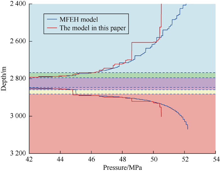
Based on the Gas Research Institute (GRI) test data of the Waskom oil field in Harrison County, Texas (Table 2), the model in this paper and MFEH model were used to calculate the hydraulic fracture height change respectively. The formation was divided into 6 layers and the third layer was perforated. As shown in Fig. 4, the variation trend of the fracture height calculated by the model in this paper is quite consistent with that of MFEH model on the whole. When the fracture height is small, there is little difference between the results calculated by the model in this paper and MFEH model. When the fracture height gets larger, the fracture height calculated by the model in this paper shows a step-like growth trend. This is because the fracture height does not grow continuously during the fracturing process. When the pressure reaches the extension pressure of the fracture growth, the fracture suddenly extends, causing the fluid pressure in the fracture to drop. Then as the pumping time increases, the fluid pressure in the fracture rises again, and fracture propagates again when the fracture extension pressure is reached. Therefore, the fracture height increases stepwise. In addition, the comparison results show that the fracture height calculated by the model in this paper penetrates the top boundary when the fracturing fluid pressure at the perforation position is 50.51 MPa, while the fracture height calculated by MFEH model penetrates the top boundary when the fracturing fluid pressure at the perforation position is 52.21 MPa. This indicates that if the influ-ence of stress concentration in the plastic zone at the fracture tip is not considered, the ability of fracture height growth may be underestimated. In the actual fracturing operation, with such underestimation, the fracture designed may penetrate through layers, causing the break of the upper stratum and thus serious accident in fracturing.
Note: The density of fracturing fluid is 1 100 kg/m3, the perforation depth is 2820.924 m, and the fracture toughness of the formation rock is 2.197 68 MPa•m1/2.
Fig. 4.
Comparison of the fracture height profiles calculated by the model in this paper and MFEH model.
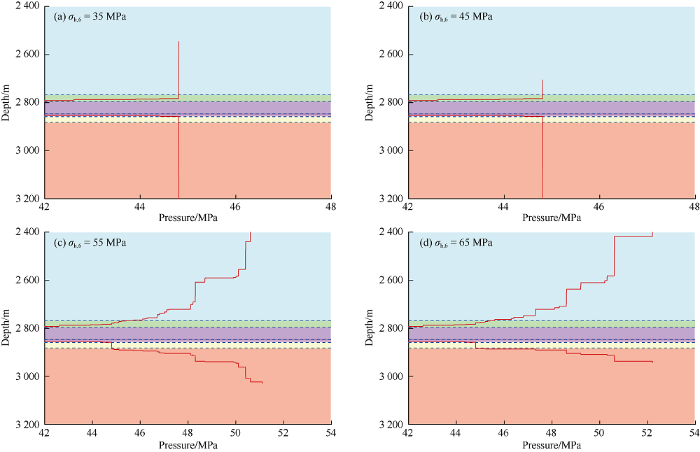
3.1. Influence of underlying strata in-situ stress on fracture growth
In order to study the influence of underlying stratum in-situ stress on the fracture height growth, the underlying strata in-situ stress (σh,6) was set to be 35, 45, 55, 65 MPa, and the variation curves of fracture height under different underlying stratum in-situ stresses were plotted (Fig. 5). When the in-situ stress of the underlying stratum is less than or equal to 45 MPa, since the in-situ stresses of the fifth layer and the sixth layer are relatively small, the lower fracture tip rapidly extends to the lower boundary when the fracturing fluid pressure at the perforation position reaches 44.81 MPa; When in-situ stress of the underlying stratum is greater than or equal to 55 MPa, it is difficult for the lower tip to extend. When the in-situ stress of the underlying stratum reaches 65 MPa, the fracture extends limitedly in the underlying stratum, and the step-like growth of the fracture height with pressure buildup stops near the interface between the fifth layer and the sixth layer. In general, as the in-situ stress of the underlying stratum increases, it becomes more and more difficult for the fracture to extend downward.
Fig. 5.
Influence of underlying stratum in-situ stress on fracture height growth.
3.2. Influence of overlying stratum in-situ stress on fracture growth
When the overlying stratum in-situ stress (σh,1) was set at 35, 45, 55, 65 MPa, the model in this paper was used to calculate and plot the hydraulic fracture height growth curves (Fig. 6). When the overlying stratum is only 35 MPa in in-situ stress, it has worse blocking effect to the fracture growth. When the fracturing fluid pressure at the perforation position reaches 46.21 MPa, the upper fracture tip becomes unstable, and the fracture height rapidly increases and reaches the top boundary (Fig. 6a). As the in-situ stress of the overlying stratum increases, the growth of the upper fracture tip becomes increasingly difficult. When the in-situ stress of the overlying stratum reaches 55 MPa, the upper fracture tip cannot reach the top boundary. When the in-situ stress of the overlying stratum reaches 65 MPa, it is difficult for the upper fracture tip to enter the upper stratum, and the fracture grows in a relatively flat pattern, the fracture height is maintained at the interface between the first layer and the second layer. The fracture mainly extends to the lower stratum, penetrating the bottom boundary.
Fig. 6.
Influence of in-situ stress of overlying stratum on fracture height growth.
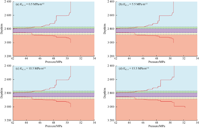
3.3. Influence of rock fracture toughness of underlying stratum on fracture height growth
The rock fracture toughness (KIC,6) of the underlying stratum was set at 0.5, 5.5, 10.5 and 15.5 MPa•m 1/2 respectively. The corresponding hydraulic fracture height was calculated by using the model in this paper. As shown in Fig. 7, as the rock fracture toughness of the underlying stratum increases, the fracture height growth has no obvious changes. Therefore, the rock fracture toughness of the underlying stratum has little effect on the fracture height growth, and its increase only inhibits the fracture height growth to some extent.
Fig. 7.
Influence of rock fracture toughness of underlying stratum on fracture height growth.
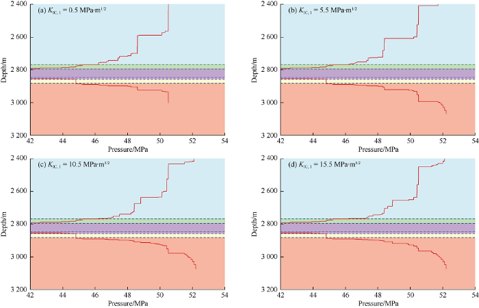
3.4. Influence of rock fracture toughness of overlying stratum on fracture height growth
The rock fracture toughness (KIC,1) of the overlying stratum was set at 0.5, 5.5, 10.5 and 15.5 MPa•m1/2 respectively. The hydraulic fracture height was calculated using the model of this paper. As shown in Fig. 8, when the rock fracture toughness of the overlying stratum is very small, the fracture easily penetrates the upper strata to reach the top boundary. As the rock fracture toughness of the overlying stratum increases, the extension of the upper fracture tip becomes difficult, and the lower fracture tip extends more significantly downward.
Fig. 8.
Influence of rock fracture toughness of overlying stratum on fracture height growth.
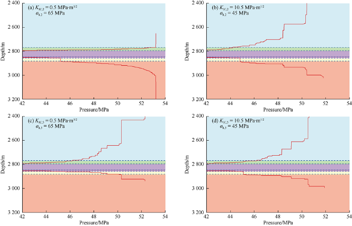
3.5. Co-effect of fracture toughness and in-situ stress on fracture height growth
In order to study the co-effect of fracture toughness and in-situ stress on the fracture growth, the high in-situ stress and low fracture toughness scenario and low in-situ stress and high fracture toughness scenario were designed. For the formation with high in-situ stress and low fracture toughness, two cases of σh,2 of 65 MPa, KIC,2 of 0.5 MPa•m1/2, and σh,5 of 65 MPa, KIC,5 of 0.5 MPa•m1/2 were set respectively (Fig. 9a, 9c). According to the results, when the in-situ stress is high, the fracture tip grows slowly, and the facture height does not grow unstably even if the fracture toughness of the formation is small. For low in-situ stress and high fracture toughness formation, two cases of σh,2 of 45 MPa, KIC,2 of 10.5 MPa•m1/2, and σh,5 of 45 MPa and KIC,5 of 10.5 MPa•m1/2 were simulated (Fig. 9b, 9d). Although the rock fracture toughness of the formation is relatively high, the in-situ stress is small, the fracture height grows rapidly and the fracture tip even grows unstably by leaps, indicating the in-situ stress plays a major role in controlling the fracture growth, while the rock fracture toughness of the formation only inhibits the growth of fracture height to some extent.
Fig. 9.
Co-effect of fracture toughness and in-situ stress on fracture height growth.
3.6. Influence of stress difference between overlying stratum and perforation layer on fracture height growth
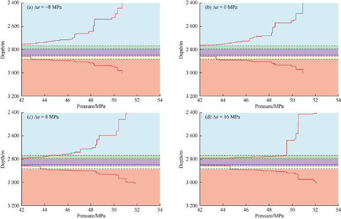
The stress difference ∆σ of the overlying stratum (the second layer) and the perforation layer was set at -8, 0, 8 and 16 MPa, respectively. The model of this paper was used to calculate and plot the fracture height growth curve. When ∆σ is -8 and 0 MPa, the in-situ stress of the overlying stratum is less than or equal to the in-situ stress of the perforation layer, and does not block the growth of the fracture height. After the fracture in the perforation layer is initiated, fracture grows in height and penetrates the perforation layer and the overlying stratum (Fig. 10a, 10b). As the in-situ stress of overlying stratum increases and exceeds the in-situ stress of perforation layer, the stress difference increases gradually, and it becomes more and more difficult for the fracture to extend upward. Compared with Fig. 10a and 10b, the fracture grows slowly in the overlying stratum (Fig. 10c, 10d). The increase of ∆σ effectively prevents the fracture from extending upward, which has a significant inhibitory effect on the fracture height growth.
Fig. 10.
Effect of stress difference between overlying stratum and perforation layer on fracture height growth.
3.7. Influence of fracturing fluid density on fracture height growth
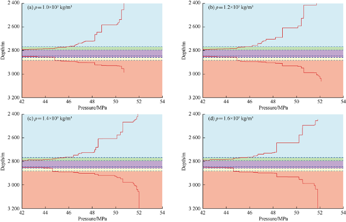
The fracturing fluid density was set at 1.0×10³, 1.2×10³, 1.4×10³, and 1.6×10³ kg/m3, respectively, and the influence of the fracturing fluid density on the fracture growth was analyzed (Fig. 11). As the density of the fracturing fluid increases, the gravity of the fracturing fluid in the fracture increases, and the net pressure value at the lower fracture tip becomes greater than that at the upper fracture tip. The greater the fracturing fluid density, the greater the difference of the net pressure between the upper and lower tips of the fracture will be, which decelerates of the growth of the upper fracture tip and accelerates the growth of lower fracture tip. Consequently, the height and shape of the entire fracture are affected. When the density of the fracturing fluid is small, the net pressure difference between the upper and lower tips of the fracture is small. In other words, the difference in the stress intensity factor of the upper and lower tips is small. Generally, the in-situ stress gradually decreases in upper layers and both the rock compaction and fracture toughness decrease. The fracture tends to extend upward and reach the top boundary. Such rules can guide the fracturing operation. To some extent, the fracture height extension can be controlled by adjusting the fracturing fluid density.
Fig. 11.
Effect of fracturing fluid density on fracture growth.
3.8. Discussion
Above calculation examples show that the in-situ stress and rock fracture toughness of formation and the fracturing fluid density all have certain effect on the fracture height growth. The fracture height model presented in this paper can calculate and predict fracture height of multi-layered formation with high in-situ stress. However, in order to simplify the calculation during the establishment of the fracture height model, the influence of some factors on the fracture height extension is neglected, such as the flow pressure drop along the fracture height direction of the fluid in the fracture, and the influence of in-situ stress and fracture propagation on the rock fracture toughness of the formation. In the future, relevant research is still needed to improve the fracture height model of this paper, so that the model can be better used to calculate and predict fracture height in field fracturing. In addition, the model in this paper mainly studies the influence of fracturing fluid pressure on fracture height growth under different conditions and does not establish a three-dimensional model of fracture extension, so it can’t do the coupling calculation of fracture length and height growth.
4. Conclusions
During hydraulic fracturing, the fracture height shows a step-like growth. The larger the fracture height, the more obvious this phenomenon will be. The in-situ stress has significant influence on the fracture height extension. When the in-situ stress is small (in-situ stress of the underlying stratum or the overlying stratum is lower than 45 MPa), the fracture tip is likely to extend unstably, and the fracture height increases rapidly. With the increase of in-situ stress, when the in-situ stress of the underlying stratum or the overlying stratum reaches 55 MPa, the growth of fracture height becomes more and more difficult. The in-situ stress plays a major role in controlling the fracture height growth, while the rock toughness only hinders the fracture growth to a certain extent. The increase of fracturing fluid density is beneficial to the growth of the lower fracture tip. When the fluid density is less than 1.2×10³ kg/m3, the fracture height is likely to extend upward. As the fluid density increases, the fracture height mainly extends downward.
Nomenclature
a—half height of the fracture, m;
B—half height of the fracture with the influence of the plastic zone taken into account, m;
C—half height of the fracture not considering the influence of the plastic zone, m;
dref—vertical depth of the perforation position, m ;
dmid —vertical depth of the middle of the fracture, m;
e—plastic zone size, m;
g—gravity acceleration, m/s2;
hi—thickness of the layer i, i =1, 2, …n, m;
KIC—rock fracture toughness of the formation, MPa•m1/2;
KI—stress intensity factor, MPa•m1/2;
K°—stress intensity factor of tensile stress between equivalent fracture surfaces in the plastic zone, MPa•m1/2;
K′′—stress intensity factor of the fracture tip with the influence of the plastic zone at the fracture tip taken into account, MPa•m1/2;
KI-—stress intensity factor of the upper fracture tip not considering the influence of the plastic zone, MPa•m1 /2;
KI+—stress intensity factor of the lower tip not considering the influence of the plastic zone, MPa•m1/2;
KI2-—stress intensity factor of the upper tip with the influence of the plastic zone taken into account, MPa•m1/2;
KI2+—stress intensity factor of the lower tip with the influence of the plastic zone taken into account, MPa•m1/2;
$K_{I+}^{'}$—stress intensity factor generated by the stress closing the fracture in the plastic zone at the lower fracture tip, MPa•m1/2;
n—total number of layers;
pmid—pressure of the fracturing fluid in the middle of the fracture, MPa;
pnet—net pressure of the fluid at any point in the fracture, MPa;
pref—pumping pressure of the fracturing fluid at the perforation position, MPa;
r—distance from any point in the plastic zone of the fracture end to the end of the fracture, m;
r1—radius of the plastic zone at the fracture end, m;
x—extension direction of hydraulic fracture height, m;
y—extension direction of hydraulic fracture width, m;
θ—the polar angle generated by counter-clockwise rotation to any point in the plastic zone with the fracture end as the endpoint of polar coordinates, (°);
υ—Poisson's ratio of the rock, dimensionless;
ρ—fracturing fluid density, kg/m3;
σ—distributed load, MPa;
σy—tensile stress between equivalent crack surfaces, MPa;
σh,i—the horizontal minimum principal stress of layer i, i = 1, 2, ..., n, MPa;
σ1, σ2, σ3— three principal stresses at any point of the fracture end, MPa.
Basic research progress and development suggestions on hydraulic fracturing
1
2019
... As an efficient stimulation technology, hydraulic fracturing has been widely used in various oil and gas reservoirs with remarkable achievements. However, current existing hydraulic fracture models have certain limitations in field application and are not suitable for complex wells or formations[1,2], which limits the development of hydraulic fracturing technology. The fracture height, as the input of the two-dimensional hydraulic fracture model and the output of the three- dimensional model, is an important factor affecting the accurate solution with the hydraulic fracturing model. The calculation of fracture height is regarded as a key issue in the study of hydraulic fracture models[3,4]. Especially on the technical background of large-scale fracturing for unconventional reservoirs represented by shale gas[5,6,7], how to accurately predict and control the fracture height has becomes the key deciding the success of fracturing operation. For shale reservoirs with shallow burial depth and low in-situ stresses, the existent fracture height models are highly applicable[8]. But for deep and complex formations with multiple layers and high stresses, it is often difficult to predict the hydraulic fracture height[9,10]. Therefore, a new method able to accurately calculate the hydraulic fracture height in such formations is urgently needed. ...
Experimental investigation on fracture initiation and non-planar propagation of hydraulic fractures in coal seams
1
2017
... As an efficient stimulation technology, hydraulic fracturing has been widely used in various oil and gas reservoirs with remarkable achievements. However, current existing hydraulic fracture models have certain limitations in field application and are not suitable for complex wells or formations[1,2], which limits the development of hydraulic fracturing technology. The fracture height, as the input of the two-dimensional hydraulic fracture model and the output of the three- dimensional model, is an important factor affecting the accurate solution with the hydraulic fracturing model. The calculation of fracture height is regarded as a key issue in the study of hydraulic fracture models[3,4]. Especially on the technical background of large-scale fracturing for unconventional reservoirs represented by shale gas[5,6,7], how to accurately predict and control the fracture height has becomes the key deciding the success of fracturing operation. For shale reservoirs with shallow burial depth and low in-situ stresses, the existent fracture height models are highly applicable[8]. But for deep and complex formations with multiple layers and high stresses, it is often difficult to predict the hydraulic fracture height[9,10]. Therefore, a new method able to accurately calculate the hydraulic fracture height in such formations is urgently needed. ...
Research on rock brittleness experiment and logging prediction of hydraulic fracture height and width
1
2013
... As an efficient stimulation technology, hydraulic fracturing has been widely used in various oil and gas reservoirs with remarkable achievements. However, current existing hydraulic fracture models have certain limitations in field application and are not suitable for complex wells or formations[1,2], which limits the development of hydraulic fracturing technology. The fracture height, as the input of the two-dimensional hydraulic fracture model and the output of the three- dimensional model, is an important factor affecting the accurate solution with the hydraulic fracturing model. The calculation of fracture height is regarded as a key issue in the study of hydraulic fracture models[3,4]. Especially on the technical background of large-scale fracturing for unconventional reservoirs represented by shale gas[5,6,7], how to accurately predict and control the fracture height has becomes the key deciding the success of fracturing operation. For shale reservoirs with shallow burial depth and low in-situ stresses, the existent fracture height models are highly applicable[8]. But for deep and complex formations with multiple layers and high stresses, it is often difficult to predict the hydraulic fracture height[9,10]. Therefore, a new method able to accurately calculate the hydraulic fracture height in such formations is urgently needed. ...
A 3-D model for simulation of weak interface slippage for fracture height containment in shale reservoirs
1
2018
... As an efficient stimulation technology, hydraulic fracturing has been widely used in various oil and gas reservoirs with remarkable achievements. However, current existing hydraulic fracture models have certain limitations in field application and are not suitable for complex wells or formations[1,2], which limits the development of hydraulic fracturing technology. The fracture height, as the input of the two-dimensional hydraulic fracture model and the output of the three- dimensional model, is an important factor affecting the accurate solution with the hydraulic fracturing model. The calculation of fracture height is regarded as a key issue in the study of hydraulic fracture models[3,4]. Especially on the technical background of large-scale fracturing for unconventional reservoirs represented by shale gas[5,6,7], how to accurately predict and control the fracture height has becomes the key deciding the success of fracturing operation. For shale reservoirs with shallow burial depth and low in-situ stresses, the existent fracture height models are highly applicable[8]. But for deep and complex formations with multiple layers and high stresses, it is often difficult to predict the hydraulic fracture height[9,10]. Therefore, a new method able to accurately calculate the hydraulic fracture height in such formations is urgently needed. ...
Fracture propagation laws in staged hydraulic fracturing and their effects on fracture conductivities
1
2017
... As an efficient stimulation technology, hydraulic fracturing has been widely used in various oil and gas reservoirs with remarkable achievements. However, current existing hydraulic fracture models have certain limitations in field application and are not suitable for complex wells or formations[1,2], which limits the development of hydraulic fracturing technology. The fracture height, as the input of the two-dimensional hydraulic fracture model and the output of the three- dimensional model, is an important factor affecting the accurate solution with the hydraulic fracturing model. The calculation of fracture height is regarded as a key issue in the study of hydraulic fracture models[3,4]. Especially on the technical background of large-scale fracturing for unconventional reservoirs represented by shale gas[5,6,7], how to accurately predict and control the fracture height has becomes the key deciding the success of fracturing operation. For shale reservoirs with shallow burial depth and low in-situ stresses, the existent fracture height models are highly applicable[8]. But for deep and complex formations with multiple layers and high stresses, it is often difficult to predict the hydraulic fracture height[9,10]. Therefore, a new method able to accurately calculate the hydraulic fracture height in such formations is urgently needed. ...
Experimental of hydraulic fracture propagation using fixed-point multistage fracturing in a vertical well in tight sandstone reservoir
1
2018
... As an efficient stimulation technology, hydraulic fracturing has been widely used in various oil and gas reservoirs with remarkable achievements. However, current existing hydraulic fracture models have certain limitations in field application and are not suitable for complex wells or formations[1,2], which limits the development of hydraulic fracturing technology. The fracture height, as the input of the two-dimensional hydraulic fracture model and the output of the three- dimensional model, is an important factor affecting the accurate solution with the hydraulic fracturing model. The calculation of fracture height is regarded as a key issue in the study of hydraulic fracture models[3,4]. Especially on the technical background of large-scale fracturing for unconventional reservoirs represented by shale gas[5,6,7], how to accurately predict and control the fracture height has becomes the key deciding the success of fracturing operation. For shale reservoirs with shallow burial depth and low in-situ stresses, the existent fracture height models are highly applicable[8]. But for deep and complex formations with multiple layers and high stresses, it is often difficult to predict the hydraulic fracture height[9,10]. Therefore, a new method able to accurately calculate the hydraulic fracture height in such formations is urgently needed. ...
Study on the mechanism of rupture and propagation of T-type fractures in coal fracturing
1
2018
... As an efficient stimulation technology, hydraulic fracturing has been widely used in various oil and gas reservoirs with remarkable achievements. However, current existing hydraulic fracture models have certain limitations in field application and are not suitable for complex wells or formations[1,2], which limits the development of hydraulic fracturing technology. The fracture height, as the input of the two-dimensional hydraulic fracture model and the output of the three- dimensional model, is an important factor affecting the accurate solution with the hydraulic fracturing model. The calculation of fracture height is regarded as a key issue in the study of hydraulic fracture models[3,4]. Especially on the technical background of large-scale fracturing for unconventional reservoirs represented by shale gas[5,6,7], how to accurately predict and control the fracture height has becomes the key deciding the success of fracturing operation. For shale reservoirs with shallow burial depth and low in-situ stresses, the existent fracture height models are highly applicable[8]. But for deep and complex formations with multiple layers and high stresses, it is often difficult to predict the hydraulic fracture height[9,10]. Therefore, a new method able to accurately calculate the hydraulic fracture height in such formations is urgently needed. ...
Hydraulic fracture height limits and fault interactions in tight oil and gas formations
1
2013
... As an efficient stimulation technology, hydraulic fracturing has been widely used in various oil and gas reservoirs with remarkable achievements. However, current existing hydraulic fracture models have certain limitations in field application and are not suitable for complex wells or formations[1,2], which limits the development of hydraulic fracturing technology. The fracture height, as the input of the two-dimensional hydraulic fracture model and the output of the three- dimensional model, is an important factor affecting the accurate solution with the hydraulic fracturing model. The calculation of fracture height is regarded as a key issue in the study of hydraulic fracture models[3,4]. Especially on the technical background of large-scale fracturing for unconventional reservoirs represented by shale gas[5,6,7], how to accurately predict and control the fracture height has becomes the key deciding the success of fracturing operation. For shale reservoirs with shallow burial depth and low in-situ stresses, the existent fracture height models are highly applicable[8]. But for deep and complex formations with multiple layers and high stresses, it is often difficult to predict the hydraulic fracture height[9,10]. Therefore, a new method able to accurately calculate the hydraulic fracture height in such formations is urgently needed. ...
Deposition confines hydraulic fracture length
1
2008
... As an efficient stimulation technology, hydraulic fracturing has been widely used in various oil and gas reservoirs with remarkable achievements. However, current existing hydraulic fracture models have certain limitations in field application and are not suitable for complex wells or formations[1,2], which limits the development of hydraulic fracturing technology. The fracture height, as the input of the two-dimensional hydraulic fracture model and the output of the three- dimensional model, is an important factor affecting the accurate solution with the hydraulic fracturing model. The calculation of fracture height is regarded as a key issue in the study of hydraulic fracture models[3,4]. Especially on the technical background of large-scale fracturing for unconventional reservoirs represented by shale gas[5,6,7], how to accurately predict and control the fracture height has becomes the key deciding the success of fracturing operation. For shale reservoirs with shallow burial depth and low in-situ stresses, the existent fracture height models are highly applicable[8]. But for deep and complex formations with multiple layers and high stresses, it is often difficult to predict the hydraulic fracture height[9,10]. Therefore, a new method able to accurately calculate the hydraulic fracture height in such formations is urgently needed. ...
Study of hydraulic fracturing processes in shale formations with complex geological settings
1
2017
... As an efficient stimulation technology, hydraulic fracturing has been widely used in various oil and gas reservoirs with remarkable achievements. However, current existing hydraulic fracture models have certain limitations in field application and are not suitable for complex wells or formations[1,2], which limits the development of hydraulic fracturing technology. The fracture height, as the input of the two-dimensional hydraulic fracture model and the output of the three- dimensional model, is an important factor affecting the accurate solution with the hydraulic fracturing model. The calculation of fracture height is regarded as a key issue in the study of hydraulic fracture models[3,4]. Especially on the technical background of large-scale fracturing for unconventional reservoirs represented by shale gas[5,6,7], how to accurately predict and control the fracture height has becomes the key deciding the success of fracturing operation. For shale reservoirs with shallow burial depth and low in-situ stresses, the existent fracture height models are highly applicable[8]. But for deep and complex formations with multiple layers and high stresses, it is often difficult to predict the hydraulic fracture height[9,10]. Therefore, a new method able to accurately calculate the hydraulic fracture height in such formations is urgently needed. ...
Propagation law of hydraulic fractures during multi-staged horizontal well fracturing in a tight reservoir
1
2018
... During the fracturing treatment in the multi-layered complex formation with high stresses, the fracture height growth is controlled by many factors, including the bedding interface and its corresponding shear strength, pumping pressure, fracturing fluid leak-off, the development of natural fractures, and the density and viscosity of the fracturing fluid [11,12,13,14,15,16]. Despite of a variety of factors affecting the growth of fracture height in complex formation, there existing an upper limit for the fracture height under a certain pumping pressure, i.e. the equilibrium height theory[17]. When the stress intensity factors at the upper and lower tips of the fracture are smaller than the rock toughness of the corresponding locations, the fracture tip stop growing. Otherwise, the fracture tip grows and the fracture height increases. ...
Brittleness evaluation of coal based on statistical damage and energy evolution theory
1
2019
... During the fracturing treatment in the multi-layered complex formation with high stresses, the fracture height growth is controlled by many factors, including the bedding interface and its corresponding shear strength, pumping pressure, fracturing fluid leak-off, the development of natural fractures, and the density and viscosity of the fracturing fluid [11,12,13,14,15,16]. Despite of a variety of factors affecting the growth of fracture height in complex formation, there existing an upper limit for the fracture height under a certain pumping pressure, i.e. the equilibrium height theory[17]. When the stress intensity factors at the upper and lower tips of the fracture are smaller than the rock toughness of the corresponding locations, the fracture tip stop growing. Otherwise, the fracture tip grows and the fracture height increases. ...
The effect of Poisson's ratio on fracture height
1
1984
... During the fracturing treatment in the multi-layered complex formation with high stresses, the fracture height growth is controlled by many factors, including the bedding interface and its corresponding shear strength, pumping pressure, fracturing fluid leak-off, the development of natural fractures, and the density and viscosity of the fracturing fluid [11,12,13,14,15,16]. Despite of a variety of factors affecting the growth of fracture height in complex formation, there existing an upper limit for the fracture height under a certain pumping pressure, i.e. the equilibrium height theory[17]. When the stress intensity factors at the upper and lower tips of the fracture are smaller than the rock toughness of the corresponding locations, the fracture tip stop growing. Otherwise, the fracture tip grows and the fracture height increases. ...
Modeling of hydraulic fracture network propagation in a naturally fractured formation
2
2011
... During the fracturing treatment in the multi-layered complex formation with high stresses, the fracture height growth is controlled by many factors, including the bedding interface and its corresponding shear strength, pumping pressure, fracturing fluid leak-off, the development of natural fractures, and the density and viscosity of the fracturing fluid [11,12,13,14,15,16]. Despite of a variety of factors affecting the growth of fracture height in complex formation, there existing an upper limit for the fracture height under a certain pumping pressure, i.e. the equilibrium height theory[17]. When the stress intensity factors at the upper and lower tips of the fracture are smaller than the rock toughness of the corresponding locations, the fracture tip stop growing. Otherwise, the fracture tip grows and the fracture height increases. ...
... Since the 1970s, researchers have established many fracture models for calculating the fracture height. The fracture height prediction model proposed by Simonson et al.[18] divides the formation into three symmetrical layers for both upper and lower parts and assumes the overlying layers and the underlying layers are identical in physical properties, which is quite different from the actual strata during fracturing treatment. Thus, this model is not very practical. Ahmed[19], Newberry et al.[20] and Economides et al.[21] modified the Simonson’s model and divided the strata into three set of asymmetric upper and lower layers and assumed the overlying layers and the underlying layers had different physical properties, which makes the model more practical. Considering different petrophysical properties of different strata, Fung et al.[22] considered the different petrophysical properties of different strata and developed a fracture height model containing six layers, which assumed that the net pressure within the fracture was constant along the fracture height direction. The fracture height prediction model established by Economides et al.[23] takes the variation of the net pressure within the fracture along the height direction into account. Weng et al.[14] modified and improved the Economides’ model. Liu et al.[24-25] put forward a more rigorous model called multilayer fracture-equilibrium- height (MFEH), which can be used to calculate fracture height in the formation with arbitrary layers. ...
Hydraulic-fracture-height growth: Real data
1
2012
... During the fracturing treatment in the multi-layered complex formation with high stresses, the fracture height growth is controlled by many factors, including the bedding interface and its corresponding shear strength, pumping pressure, fracturing fluid leak-off, the development of natural fractures, and the density and viscosity of the fracturing fluid [11,12,13,14,15,16]. Despite of a variety of factors affecting the growth of fracture height in complex formation, there existing an upper limit for the fracture height under a certain pumping pressure, i.e. the equilibrium height theory[17]. When the stress intensity factors at the upper and lower tips of the fracture are smaller than the rock toughness of the corresponding locations, the fracture tip stop growing. Otherwise, the fracture tip grows and the fracture height increases. ...
Effect of formation modulus contrast on hydraulic fracture height containment
1
2008
... During the fracturing treatment in the multi-layered complex formation with high stresses, the fracture height growth is controlled by many factors, including the bedding interface and its corresponding shear strength, pumping pressure, fracturing fluid leak-off, the development of natural fractures, and the density and viscosity of the fracturing fluid [11,12,13,14,15,16]. Despite of a variety of factors affecting the growth of fracture height in complex formation, there existing an upper limit for the fracture height under a certain pumping pressure, i.e. the equilibrium height theory[17]. When the stress intensity factors at the upper and lower tips of the fracture are smaller than the rock toughness of the corresponding locations, the fracture tip stop growing. Otherwise, the fracture tip grows and the fracture height increases. ...
Hydraulic fracture mechanics
1
1995
... During the fracturing treatment in the multi-layered complex formation with high stresses, the fracture height growth is controlled by many factors, including the bedding interface and its corresponding shear strength, pumping pressure, fracturing fluid leak-off, the development of natural fractures, and the density and viscosity of the fracturing fluid [11,12,13,14,15,16]. Despite of a variety of factors affecting the growth of fracture height in complex formation, there existing an upper limit for the fracture height under a certain pumping pressure, i.e. the equilibrium height theory[17]. When the stress intensity factors at the upper and lower tips of the fracture are smaller than the rock toughness of the corresponding locations, the fracture tip stop growing. Otherwise, the fracture tip grows and the fracture height increases. ...
Containment of massive hydraulic fractures
1
1978
... Since the 1970s, researchers have established many fracture models for calculating the fracture height. The fracture height prediction model proposed by Simonson et al.[18] divides the formation into three symmetrical layers for both upper and lower parts and assumes the overlying layers and the underlying layers are identical in physical properties, which is quite different from the actual strata during fracturing treatment. Thus, this model is not very practical. Ahmed[19], Newberry et al.[20] and Economides et al.[21] modified the Simonson’s model and divided the strata into three set of asymmetric upper and lower layers and assumed the overlying layers and the underlying layers had different physical properties, which makes the model more practical. Considering different petrophysical properties of different strata, Fung et al.[22] considered the different petrophysical properties of different strata and developed a fracture height model containing six layers, which assumed that the net pressure within the fracture was constant along the fracture height direction. The fracture height prediction model established by Economides et al.[23] takes the variation of the net pressure within the fracture along the height direction into account. Weng et al.[14] modified and improved the Economides’ model. Liu et al.[24-25] put forward a more rigorous model called multilayer fracture-equilibrium- height (MFEH), which can be used to calculate fracture height in the formation with arbitrary layers. ...
Fracture height prediction
1
1988
... Since the 1970s, researchers have established many fracture models for calculating the fracture height. The fracture height prediction model proposed by Simonson et al.[18] divides the formation into three symmetrical layers for both upper and lower parts and assumes the overlying layers and the underlying layers are identical in physical properties, which is quite different from the actual strata during fracturing treatment. Thus, this model is not very practical. Ahmed[19], Newberry et al.[20] and Economides et al.[21] modified the Simonson’s model and divided the strata into three set of asymmetric upper and lower layers and assumed the overlying layers and the underlying layers had different physical properties, which makes the model more practical. Considering different petrophysical properties of different strata, Fung et al.[22] considered the different petrophysical properties of different strata and developed a fracture height model containing six layers, which assumed that the net pressure within the fracture was constant along the fracture height direction. The fracture height prediction model established by Economides et al.[23] takes the variation of the net pressure within the fracture along the height direction into account. Weng et al.[14] modified and improved the Economides’ model. Liu et al.[24-25] put forward a more rigorous model called multilayer fracture-equilibrium- height (MFEH), which can be used to calculate fracture height in the formation with arbitrary layers. ...
Prediction of vertical hydraulic fracture migration using compressional and shear wave slowness
1
1985
... Since the 1970s, researchers have established many fracture models for calculating the fracture height. The fracture height prediction model proposed by Simonson et al.[18] divides the formation into three symmetrical layers for both upper and lower parts and assumes the overlying layers and the underlying layers are identical in physical properties, which is quite different from the actual strata during fracturing treatment. Thus, this model is not very practical. Ahmed[19], Newberry et al.[20] and Economides et al.[21] modified the Simonson’s model and divided the strata into three set of asymmetric upper and lower layers and assumed the overlying layers and the underlying layers had different physical properties, which makes the model more practical. Considering different petrophysical properties of different strata, Fung et al.[22] considered the different petrophysical properties of different strata and developed a fracture height model containing six layers, which assumed that the net pressure within the fracture was constant along the fracture height direction. The fracture height prediction model established by Economides et al.[23] takes the variation of the net pressure within the fracture along the height direction into account. Weng et al.[14] modified and improved the Economides’ model. Liu et al.[24-25] put forward a more rigorous model called multilayer fracture-equilibrium- height (MFEH), which can be used to calculate fracture height in the formation with arbitrary layers. ...
Petroleum production systems. 2nd ed
1
2012
... Since the 1970s, researchers have established many fracture models for calculating the fracture height. The fracture height prediction model proposed by Simonson et al.[18] divides the formation into three symmetrical layers for both upper and lower parts and assumes the overlying layers and the underlying layers are identical in physical properties, which is quite different from the actual strata during fracturing treatment. Thus, this model is not very practical. Ahmed[19], Newberry et al.[20] and Economides et al.[21] modified the Simonson’s model and divided the strata into three set of asymmetric upper and lower layers and assumed the overlying layers and the underlying layers had different physical properties, which makes the model more practical. Considering different petrophysical properties of different strata, Fung et al.[22] considered the different petrophysical properties of different strata and developed a fracture height model containing six layers, which assumed that the net pressure within the fracture was constant along the fracture height direction. The fracture height prediction model established by Economides et al.[23] takes the variation of the net pressure within the fracture along the height direction into account. Weng et al.[14] modified and improved the Economides’ model. Liu et al.[24-25] put forward a more rigorous model called multilayer fracture-equilibrium- height (MFEH), which can be used to calculate fracture height in the formation with arbitrary layers. ...
Calculation of vertical fracture containment in layered formations
1
1987
... Since the 1970s, researchers have established many fracture models for calculating the fracture height. The fracture height prediction model proposed by Simonson et al.[18] divides the formation into three symmetrical layers for both upper and lower parts and assumes the overlying layers and the underlying layers are identical in physical properties, which is quite different from the actual strata during fracturing treatment. Thus, this model is not very practical. Ahmed[19], Newberry et al.[20] and Economides et al.[21] modified the Simonson’s model and divided the strata into three set of asymmetric upper and lower layers and assumed the overlying layers and the underlying layers had different physical properties, which makes the model more practical. Considering different petrophysical properties of different strata, Fung et al.[22] considered the different petrophysical properties of different strata and developed a fracture height model containing six layers, which assumed that the net pressure within the fracture was constant along the fracture height direction. The fracture height prediction model established by Economides et al.[23] takes the variation of the net pressure within the fracture along the height direction into account. Weng et al.[14] modified and improved the Economides’ model. Liu et al.[24-25] put forward a more rigorous model called multilayer fracture-equilibrium- height (MFEH), which can be used to calculate fracture height in the formation with arbitrary layers. ...
Reservoir stimulation. 3rd ed
1
2000
... Since the 1970s, researchers have established many fracture models for calculating the fracture height. The fracture height prediction model proposed by Simonson et al.[18] divides the formation into three symmetrical layers for both upper and lower parts and assumes the overlying layers and the underlying layers are identical in physical properties, which is quite different from the actual strata during fracturing treatment. Thus, this model is not very practical. Ahmed[19], Newberry et al.[20] and Economides et al.[21] modified the Simonson’s model and divided the strata into three set of asymmetric upper and lower layers and assumed the overlying layers and the underlying layers had different physical properties, which makes the model more practical. Considering different petrophysical properties of different strata, Fung et al.[22] considered the different petrophysical properties of different strata and developed a fracture height model containing six layers, which assumed that the net pressure within the fracture was constant along the fracture height direction. The fracture height prediction model established by Economides et al.[23] takes the variation of the net pressure within the fracture along the height direction into account. Weng et al.[14] modified and improved the Economides’ model. Liu et al.[24-25] put forward a more rigorous model called multilayer fracture-equilibrium- height (MFEH), which can be used to calculate fracture height in the formation with arbitrary layers. ...
A rigorous hydraulic-fracture equilibrium-height model for multilayer formations
4
2017
... Since the 1970s, researchers have established many fracture models for calculating the fracture height. The fracture height prediction model proposed by Simonson et al.[18] divides the formation into three symmetrical layers for both upper and lower parts and assumes the overlying layers and the underlying layers are identical in physical properties, which is quite different from the actual strata during fracturing treatment. Thus, this model is not very practical. Ahmed[19], Newberry et al.[20] and Economides et al.[21] modified the Simonson’s model and divided the strata into three set of asymmetric upper and lower layers and assumed the overlying layers and the underlying layers had different physical properties, which makes the model more practical. Considering different petrophysical properties of different strata, Fung et al.[22] considered the different petrophysical properties of different strata and developed a fracture height model containing six layers, which assumed that the net pressure within the fracture was constant along the fracture height direction. The fracture height prediction model established by Economides et al.[23] takes the variation of the net pressure within the fracture along the height direction into account. Weng et al.[14] modified and improved the Economides’ model. Liu et al.[24-25] put forward a more rigorous model called multilayer fracture-equilibrium- height (MFEH), which can be used to calculate fracture height in the formation with arbitrary layers. ...
... When the influence of the plastic zone at the fracture tip is not considered (the blue area in Fig. 3), referring to Liu et al.[24,25] model, the stress intensity factors at the upper and lower ends of the fracture can be expressed as: ...
... Under the same conditions, the fracture height calculation results of the model in this paper are compared with those of two models (FracPro, MFEH) commonly used in the oil industry to verify the accuracy of the model of this paper. The Fayetteville shale formation parameters (Table 1) were used in the calculation[24], and the formation was divided into 7 layers. When the fracturing fluid pressure at the perforating position is 31.3 MPa, the fracture height calculated by the MFEH model is 60.61 m, and that by the model in this paper is 66.47 m; when the fracturing fluid pressure at the perforating position is 32.0 MPa, the fracture height calculated by the model in this paper is 71.24 m, and that by FracPro model is 82.68 m. It can be seen from the comparison that the fracture height calculated by the model of this paper is higher than that of the MFEH model and lower than that of the FracPro model, which is close to the results calculated by the commonly used models, indicating that this model has higher accuracy. Since the model of this paper considers the influence of the plastic zone at the fracture tip on the basis of the MFEH model, the plastic zone generated by the original fracture height needs to be calculated in each step of the fracture height solving and correction. Therefore, the model in this paper is lower in computational efficiency than the MFEH model. ...
... Rock physical and mechanical parameters of the Fayetteville shale formation[24]. ...
An improved equilibrium-height model for predicting hydraulic fracture height migration in multi- layered formations
2
2015
... Since the 1970s, researchers have established many fracture models for calculating the fracture height. The fracture height prediction model proposed by Simonson et al.[18] divides the formation into three symmetrical layers for both upper and lower parts and assumes the overlying layers and the underlying layers are identical in physical properties, which is quite different from the actual strata during fracturing treatment. Thus, this model is not very practical. Ahmed[19], Newberry et al.[20] and Economides et al.[21] modified the Simonson’s model and divided the strata into three set of asymmetric upper and lower layers and assumed the overlying layers and the underlying layers had different physical properties, which makes the model more practical. Considering different petrophysical properties of different strata, Fung et al.[22] considered the different petrophysical properties of different strata and developed a fracture height model containing six layers, which assumed that the net pressure within the fracture was constant along the fracture height direction. The fracture height prediction model established by Economides et al.[23] takes the variation of the net pressure within the fracture along the height direction into account. Weng et al.[14] modified and improved the Economides’ model. Liu et al.[24-25] put forward a more rigorous model called multilayer fracture-equilibrium- height (MFEH), which can be used to calculate fracture height in the formation with arbitrary layers. ...
... When the influence of the plastic zone at the fracture tip is not considered (the blue area in Fig. 3), referring to Liu et al.[24,25] model, the stress intensity factors at the upper and lower ends of the fracture can be expressed as: ...
On the elastic-plastic deformation of a sheet containing an edge crack
1
1975
... There is significant stress concentration at the fracture tip during hydraulic fracturing[26,27,28]. Under the high stress, the rock at the fracture tip changes from elastic state to plastic state. When the rock is plastic, the stress intensity factor at the fracture tip cannot be calculated with the classical fracture mechanics theoretical model because the actual fracture extension changes. As shown in Fig. 1, if the influence of stress concentration in the plastic zone at the fracture tip is not considered, the left and right end points of the fracture are A1 and B1, respectively, and the corresponding fracture height is 2a. But if the influence of stress concentration in the plastic zone at the fracture tip is considered, the left and right end points of the fracture can be extended to A2 and B2, and the corresponding fracture height is 2(a+e), showing the significant change of fracture height. ...
Extension calculation of vertical fracture considering fracture tip plasticity
1
2008
... There is significant stress concentration at the fracture tip during hydraulic fracturing[26,27,28]. Under the high stress, the rock at the fracture tip changes from elastic state to plastic state. When the rock is plastic, the stress intensity factor at the fracture tip cannot be calculated with the classical fracture mechanics theoretical model because the actual fracture extension changes. As shown in Fig. 1, if the influence of stress concentration in the plastic zone at the fracture tip is not considered, the left and right end points of the fracture are A1 and B1, respectively, and the corresponding fracture height is 2a. But if the influence of stress concentration in the plastic zone at the fracture tip is considered, the left and right end points of the fracture can be extended to A2 and B2, and the corresponding fracture height is 2(a+e), showing the significant change of fracture height. ...
On the crack extension in plates under plane loading and transverse shear
1
1963
... There is significant stress concentration at the fracture tip during hydraulic fracturing[26,27,28]. Under the high stress, the rock at the fracture tip changes from elastic state to plastic state. When the rock is plastic, the stress intensity factor at the fracture tip cannot be calculated with the classical fracture mechanics theoretical model because the actual fracture extension changes. As shown in Fig. 1, if the influence of stress concentration in the plastic zone at the fracture tip is not considered, the left and right end points of the fracture are A1 and B1, respectively, and the corresponding fracture height is 2a. But if the influence of stress concentration in the plastic zone at the fracture tip is considered, the left and right end points of the fracture can be extended to A2 and B2, and the corresponding fracture height is 2(a+e), showing the significant change of fracture height. ...
Yielding of steel sheet containing slits
2
1960
... There is significant stress concentration at the fracture tip during hydraulic fracturing[26,27,28]. Under the high stress, the rock at the fracture tip changes from elastic state to plastic state. When the rock is plastic, the stress intensity factor at the fracture tip cannot be calculated with the classical fracture mechanics theoretical model because the actual fracture extension changes. As shown in Fig. 1, if the influence of stress concentration in the plastic zone at the fracture tip is not considered, the left and right end points of the fracture are A1 and B1, respectively, and the corresponding fracture height is 2a. But if the influence of stress concentration in the plastic zone at the fracture tip is considered, the left and right end points of the fracture can be extended to A2 and B2, and the corresponding fracture height is 2(a+e), showing the significant change of fracture height. 10.1016/S1876-3804(20)60017-9.F001
In order to further explain the influence of stress concentration in the plastic zone at the fracture tip on the fracture height, we put forward a calculation model of the plastic zone distribution at the fracture tip under plane strain condition and a calculation method of equivalent fracture height affected by the plastic zone stress in this paper. According to the theory of fracture mechanics, the stress intensity factor at the fracture tip is expressed as[30] : ...
... Dugdale[29] proposed that the fracture with the plastic zone at the tip could be replaced by an equivalent fracture, as shown in Fig. 1. The original fracture A1B1 has a height of 2a, and the equivalent fracture A2B2 has a height of 2(a+e), wherein e represents the size of plastic zone. The crack in the plastic zone is not actually opened, and the stress component at any point in the plastic zone is σy. Since the A1A2 and B1B2 segments are not fractured, the stress intensity factor at A2 and B2 of the equivalent fracture is zero. The tensile stress σy is uniformly distributed on the equivalent crack surfaces in the plastic zone, and the stress intensity factor ${K}'$produced by σy is negative because its function is to close the fracture. The absolute value of ${K}'$is equal to the stress intensity factor ${K}''$ under external load: ...
On the stress distribution in plates with collinear cuts under arbitrary loads: Proceedings of the 4th U.S
1
1962
... In order to further explain the influence of stress concentration in the plastic zone at the fracture tip on the fracture height, we put forward a calculation model of the plastic zone distribution at the fracture tip under plane strain condition and a calculation method of equivalent fracture height affected by the plastic zone stress in this paper. According to the theory of fracture mechanics, the stress intensity factor at the fracture tip is expressed as[30] : ...
On the solution of the Dugdale model
1
1978
... The three principal stresses at any point at the end of the fracture are[31,32,33]: ...
Dugdale model for two collinear unequal cracks
1
1983
... The three principal stresses at any point at the end of the fracture are[31,32,33]: ...
A practical method for determining Dugdale model solution for cracked bodies of arbitrary shape
1
1972
... The three principal stresses at any point at the end of the fracture are[31,32,33]: ...
A secant approximation for holonomic elastic-plastic incremental analysis with a von Mises yield condition
1
1986
... The rock material is subject to the Mises yield condition[34]: ...
Comparison study of hydraulic fracturing models-test case: GRI staged field experiment No.3


