


Introduction
Steam assisted gravity drainage (SAGD) is the major recovery technology for super heavy oil and oil sand. By the end of 2018, 171 SAGD horizontal well pairs had been deployed and put into production in FC Block of Xinjiang Oilfield, China, which contribute more than 1 million tons of oil output annually. As the oil production in SAGD is mainly driven by gravity, the kinetic viscosity of crude oil has an significant impact on the steam chamber expansion rate and oil production rate[1,2,3,4,5,6]. The crude oil of FC Block has a viscosity of 20-40 mPa•s at 200 °C, which is much higher than that of the Canadian oil sands (10-20 mPa•s), indicating that the oil drainage rate of SAGD in Canadian oil sands is approximately twice that of this heavy oil in FC Block, China.
The solvent-expanded SAGD (ES-SAGD) uses solvent to further reduce the oil viscosity and enhance the oil drainage rate on the basis of oil viscosity reduction by the high temperature of steam. This technology has achieved good effect on production improvement of SAGD projects in Canada[7,8,9,10,11].
As the solvent type has a major impact on the production performance of ES-SAGD, extensive laboratory studies have been performed abroad, which verified that different oil types at different temperature and pressure conditions had different optimal solvent systems. Therefore, it is necessary to screen the most suitable solvent system according to different reservoir conditions[12]. It is found from extensive literature review that the theoretical model of ES-SAGD has not been established yet, therefore, it is necessary to introduce characteristic parameters of oil viscosity reduction by solvent dissolution to modify the conventional SAGD theoretical model and analyze the oil drainage dynamics of ES-SAGD. With regard to the specified heavy oil reservoir, the effect of different solvent systems on ES-SAGD production needs to be evaluated by obtaining data from large-scale physical simulation experiments. On this basis, the steam chamber expansion characteristics, production dynamics, oil recovery and oil/steam ratio after solvent adding can be analyzed systematically, to find out the application potential of ES-SAGD in heavy oil reservoirs in China[13].
In this work, aimed at solving the problems above, oil viscosity reduction experiments by adding solvents were carried out to find out the oil viscosity reduction regularity by solvents and select the optimal solvent system; on this basis, the theoretical SAGD model was modified to build the ES-SAGD theoretical model. Large-scale 2D physical experiments were carried out guided by the ES-SAGD theories to sort out the key oil drainage mechanisms of ES-SAGD.
1. Modification of SAGD model
Experiments of oil viscosity reduction by adding different solvents were carried out to match the corresponding equations characterizing oil viscosity reduction effect of the solvents, which can precisely characterize the heavy oil viscosity reduction behaviors and the impact of solvents on the SAGD production dynamics.
1.1. Experiments of oil viscosity reduction by adding solvents
In order to avoid the experiment errors caused by the highly volatility of light hydrocarbon solvents, the experiments were conducted with HAAKE MARS III rheometer with closed test system. The test procedure was in accordance of the petroleum industry standard (SY/T 7549-2000 Determination of oil viscosity-temperature curves: Rotational viscometer method). The specified procedure is as follows: adding a certain proportion of different types of light hydrocarbon solvents into the oil and rapidly mix them evenly; pouring the mixture into the test chamber of the rheometer and seal the lid; test the airtight oil viscosity under different temperatures with magnetic stirring rotor (test conditions: the shear rate from 3 s-1 to 20 s-1, the temperature from 20 °C to 90 °C at the atmospheric pressure).
The relationships between oil viscosity and temperature of standard crude oil, 95% oil+5% n-hexane, 95% oil+5% xylene, 95% oil + 5% pentane, 95% oil+5% diesel, 95% oil + 5% naphtha, 95% oil+5% heptane were tested (Fig. 1). From the results, the oil viscosity reduction ratios of the solvents to crude oil in descending order are: n-hexane, heptane, naphtha, xylene, diesel, and pentane. In particular, the oil viscosity at 50 °C reduced from 89 066 mPa•s to 3148 mPa•s by adding 5% n-hexane, that is oil viscosity reduction ratio of 96.5%. Therefore, the n-hexane with the best viscosity reduction performance can be taken as the main solvent of the ES-SAGD solvent system.
Fig. 1.
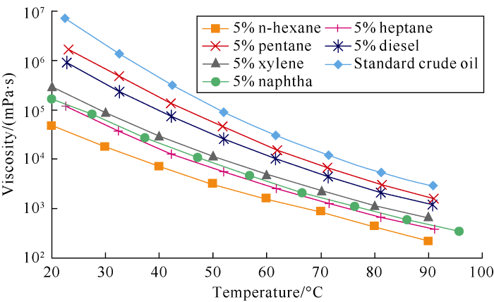
Fig. 1.
Curves of oil viscosity reduction characteristics by adding different solvents.
With the main solvent selected, the oil viscosity reduction characteristics tests by adding different proportions of n-hexane were carried out (Fig. 2). The results show that the n-hexane solvent system can reduce the oil viscosity exponentially, and the oil viscosity reduces by 90%-98% when adding 5%-10% of n-hexane. Although further increasing the solvent proportion would further reduce the oil viscosity, considering the high cost of the solvent and practical solvent recycling ratio under real reservoir conditions, excessively high solvent proportion would largely increase the economic risk. Based on the comprehensive consideration of technical and economic limits, the solvent proportion in 2D physical modelling was controlled at 10%.
Fig. 2.
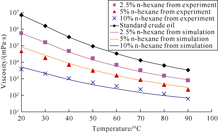
Fig. 2.
Fitting curves of oil viscosity reduction characteristics at different proportions of n-hexane.
The volume weighting of solvents and crude oil were used to calculate the density of the mixture. According to the equation (1) and through unit conversion, the kinematic viscosity of single solvent-oil mixture or multiple solvents-oil mixture can be deduced as follows:
1.2. Modification of the theoretical oil drainage model
The oil production rate at the phase of steam chamber ramp-up is:
Ideally, the time needed for the steam chamber to reach the top of the pay and the peak stable oil production rate is:
Ideally, the peak oil production rate during the phase of the steam chamber lateral expansion is:
The oil production rate in the wind-down phase after the steam chamber reaches the border of the well pair or reservoir is:
Since the temperature, pressure and injected solvent type and the ratio of solvent with steam of the reservoir or model have significant impact on the oil kinematic viscosity and mobile oil saturation, when using the equations above, the values of oil kinematic viscosity and mobile oil saturation should be determined based on temperature, pressure and injected fluid parameters in the reservoir or model at different development stages.
2. Design of ES-SAGD physical simulation experiment
2.1. Scaled modeling
According to the similarity law of 2-D SAGD physical simulation model by Butler, combined with the mixture viscosity equation (1), the basic equation of the similarity law of ES-SAGD was established as follows:
Based on the similarity law, the parameters of the 2-D scaled physical model were deduced (Table 1), and the scaled physical model and experiment flow of 2-D ES-SAGD were established.
Table 1 Scaled results of key parameters of ES-SAGD.
| Model | Temperature/°C | Porosity/ % | Movable oil saturation/% | Permeability/μm2 | Thermal diffusivity/ (m2•d-1) | Pay thickness/m | Viscosity- temperature curve index | Kinetic viscosity of oil/ (m2•d-1) | Time similarity coefficient/10-4 | Physical similarity coefficient (B3) |
|---|---|---|---|---|---|---|---|---|---|---|
| Physical model | 230 | 0.35 | 0.76 | 87.950 | 0.07 | 0.30 | 3.4 | 0.86 | 278 00.66 | 6.0 |
| Reservoir | 236 | 0.30 | 0.62 | 0.615 | 0.07 | 25.00 | 3.4 | 0.71 | 2.39 | 6.0 |
The ES-SAGD experiment system includes 4 parts (Fig. 3): (1) Injection system, including a steam generator, a high pressure pump, and an intermediate vessel, etc., which was used to saturate the model with formation water and oil during the preparation process and to inject steam and solvent during experiment process. (2) The body of the 2-D large visualized model with size of 50 cm×30 cm×4 cm (Fig. 4), in which thermal couples and pressure measuring points were uniformly deployed. (3) Data acquisition and control system, including a pressure and temperature data acquisition and control module, monitoring computer, and data acquisition and inversion software for temperature and pressure fields. (4) Producing system, including a high-temperature back pressure valve, automatic accumulator for produced steam or liquid, and electronic balance, etc.
Fig. 3.
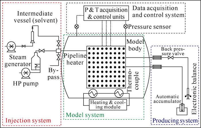
Fig. 3.
Sketch map of the experiment apparatus of 2-D scaled HTHP physical modeling.
Fig. 4.
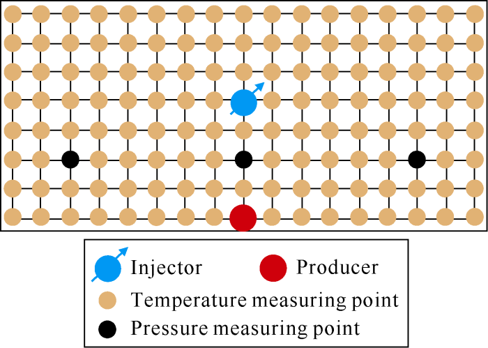
Fig. 4.
Structure of the model body.
2.2. Experiment procedure
The experiment includes 9 steps: (1) Before the experiment, the model body and pipelines were cleaned by acetone and dried by nitrogen. (2) According to the sand size distribution characteristics of the reservoir sandstone, the quartz sand of 80-120 mesh(0.125-0.180 mm) was packed in the model body and filled tightly from sand filling holes to avoid sand movement during experiments. (3) The model body was vacuumed to 1.0 kPa. (4) Water saturation: water (prepared according to the formation water salinity) was injected into the model body at the speed of 20 mL/min, then the model was aged for 48 h. (5) Oil saturation: the super heavy oil was put into the intermediate vessel, and then the vessel was put into the thermostat with the temperature rising to 80 °C to ensure the mobility of the super heavy oil; heating the model body using the insulating jacket to 80 °C for 2 h; and then injecting the de-watered oil into the model body at the speed of 10-20 mL/min, during which the water cut of the produced liquid was tested timely and the injection continued till the water cut reached 0 for 1 h. (6) After oil saturated, the model body was reduced to the reservoir temperature of 20 °C again and aged for 48 h. (7) Preheating: steam was injected into the injector and producer of the model body simultaneously, and the software was used to monitor the temperature variation of the model between the injector and producer. When the temperature reached 130 °C, the heat communication and hydraulic connection were established between the injector and producer, and the preheating stopped. The SAGD production began with steam injected in the upper injector and liquid produced from the lower producer continuously. (8) SAGD production: the steam injection rate was controlled according to the monitored temperature field. The steam injection rate gradually increased from 4 mL/min to 10 mL/min during the steam chamber ramp-up phase. The steam injection rate was maintained at 10 mL/min during the steam chamber lateral expansion phase. The steam injection rate was reduced gradually to 4 mL/min during wind-down phase. The back pressure valve was used to control the liquid production rate to ensure the production/injection ratio between 1.1 and 1.2. (9) Treatment of the produced liquid: the produced liquid was centrifuged to separate oil & water, and the rotary evaporator was used to separate and measure the produced solvent and oil.
2.3. Design of experiment case
The super heavy oil in FC Block of Xinjiang was used in the physical modeling experiment. The SARA composition of the crude oil is: saturates of 34.2%, aromatics of 20.8%, resins of 31.3%, and asphaltenes of 13.7%. According to the characteristics of high asphaltene content of the oil in this block, 3 cases of large scaled 2-D SAGD physical modeling experiments were designed: (1) SAGD with pure steam, (2) ES-SAGD with 90% steam+10% n-hexane, (3) ES-SAGD with 90% steam+9% n-hexane+1% xylene.
The cases (1) and (2) were designed to compare the steam chamber development and production dynamics of ES-SAGD by adding a small portion of solvent and SAGD with pure steam. The case (3) was designed since the xylene has good asphaltene dissolution ability; in order to avoid the plugging of the pay by asphaltene precipitation, xylene was added to evaluate the feasibility of removing asphaltene plugging and then compare the production performance of the cases (2) and (3).
To guarantee the consistency and reliability of comparison, all the 3 experiments were done at the same amount of saturated water and oil and the same injection & production parameters.
3. Analysis of the results
3.1. Steam chamber expansions
3.1.1. Steam chamber expansion rate
Comparing the temperature fields at different steam chamber expansion phases (Fig. 5) shows that the temperature fields at the steam chamber ramp-up and lateral expansion phases of cases (2) and (3) were 10-20 °C lower than those in case (1), this is because the injected cold solvent reduced the steam temperature. Although the average temperatures of cases (2) and (3) were slightly lower than case (1), through the viscosity reduction by solvent dissolution, the steam chamber expansion rates of ES-SAGD in the cases (2) and (3) were faster, which verifies that the combination of solvent and steam can have dual effect on oil viscosity reduction by solvent dissolution and high steam temperature, so the ES-SAGD has lower oil viscosity, considerable enhancement of oil drainage rate and faster steam chamber expansion rate than conventional SAGD[21,22].
Fig. 5.
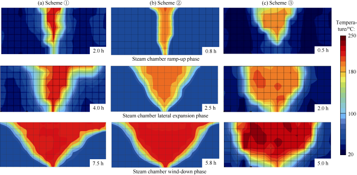
Fig. 5.
Steam chamber expansion shape of SAGD and ES-SAGD.
3.1.2. Shapes of oil drainage surface of steam chamber
Comparison of the oil drainage surfaces in the 3 cases (Figs. 6 and 7) shows the shape of the oil drainage surface is convex-curved surface in case (1), slope-linear shape in case (2), and concave-curved surface in case (3). It can be seen that the steam chamber lateral expansion rates increase gradually from case (1) to case (3), and the steam chamber lateral expansion rate in case (1) is the slowest, mainly because of the limited oil viscosity reduction effect by pure steam and the slow lateral mass transfer rate of steam to oil. In case (2), the steam with 10% solvent had much better oil viscosity reduction performance, as a result, the lateral mass transfer resistance reduced, and the oil drainage rate increased. In case (3), the xylene was added into the solvent to dissolve the asphaltene, which further improved the oil viscosity reduction rate[23], so the lateral steam chamber expansion rate and the oil drainage rate increased further.
Fig. 6.

Fig. 6.
Oil drainage surfaces inside the steam chamber of different solvent systems.
Fig. 7.

Fig. 7.
Comparison of oil drainage surface shapes inside the steam chambers of different solvent systems.
By further comparing the oil drainage surfaces, it is found that the solvent system in case (2) had evident asphaltene precipitation phenomenon, in which the asphaltene massively precipitated on the surface of the quartz sand inside the steam chamber, that can be seen from the darkness of the sand. This phenomenon indicates that the precipitated asphaltene would plug the pores of the pay and reduce the flow ability under the real reservoir conditions. In case (3) with xylene added into the solvent system, only a small amount of asphaltene precipitated on the surface of quartz sand inside the steam chamber (the color on surface of the quartz sand was brighter), which suggests that most of the asphaltene was dissolved and produced, reducing the risk of asphaltene plugging. The case (3) is able to reduce the oil viscosity and remove the asphaltene plugging effectively, so it is the optimal case out of the three.
3.2. Comparison of production dynamics
Fig. 8 shows the oil production rate curves of the 3 cases. It can be seen from this figure that the oil production rate of case (1) is much lower than that of cases (2) and (3). In case (1), the oil production rate peaked after 4.3 h, while in cases (2) and (3), the oil production rates peaked at 2.1 h and 1.9 h. The peak oil rates of the 3 cases differ widely too, and are 223, 298 and 375 g/h in cases (1), (2) and (3) respectively, that is to say the oil production rates of cases (2) and (3) are 33.6% and 68.2% higher than that of case (1).
Fig. 8.
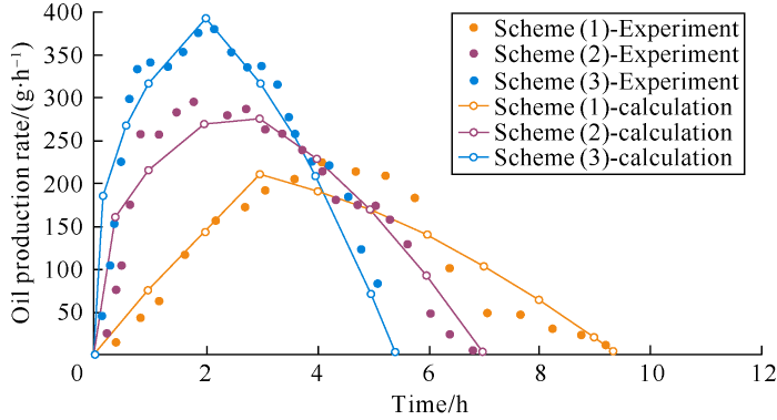
Fig. 8.
Comparison of oil production rates of SAGD and ES-SAGD.
The modified ES-SAGD theoretical model was used to match the experiment results, during which the effects of experimental temperature, pressure and injected fluid parameters on the values of ${{\nu }_{\text{mix}}}$and$\Delta {{S}_{\text{o}}}$ in different phases were considered (Fig. 8). Comparison of the oil production rates from the experiments and calculation with theoretical model shows that: in case (1), the fitting result is good in the ramp-up period, but poor in wind-down period. This is because the back pressure valve failed partially from 4 h to 6 h under high temperature, causing the production/injection ratio to reach 1.2-1.4, instead of the target of 1.1-1.2, and the peak oil rate continued consequently. The excessively high production/injection ratio then led to the steam channeling between the injector and producer, and sharp oil production rate decline after 6 h, so the disagreement between the theoretical and experimental results is significant. Steam channeling caused by the operation control is also one of the major factors affecting the production performance under practical reservoir conditions. During the experiments of cases (2) and (3), the operation was stable, and the fitting results are accurate.
The cumulative solvent injected was 230.0 mL n-hexane in case (2), and 177.5 mL n-hexane and 19.7 mL xylene in case (3). The solvent recovery rates of cases (2) and (3) were 82.3% and 86.1% respectively, indicating that ES-SAGD in confined oil reservoirs has high solvent recovery rate, avoiding benefit loss caused by the solvent leaking.
Fig. 9 shows the comparison of oil recovery factors of different cases, the oil recovery factor of case (1) was 58.2%, while those of the cases (2) and (3) were 67.9% and 74.4%, 9.7% and 16.2% higher than case (1) respectively. This indicates that ES-SAGD can accelerate the reduction of oil viscosity, and some oil in the edge and bottom of the reservoir can be tapped, enhancing the oil recovery factor. Comparison of cases (2) and (3) shows the oil recovery factor of case (3) is 6.5% higher than case (2), which indicates that adding 1.0% xylene to the steam-solvent system can give full play to its dissolution to asphaltene, reducing asphaltene precipitation and flow resistance, and making it easier to produce the crude oil.
Fig. 9.
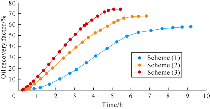
Fig. 9.
Comparison of oil recovery factors of SAGD and ES-SAGD.
Fig.10 shows the comparison of cumulative oil/steam ratios of the 3 cases. The cumulative oil/steam ratio of case (1) was 0.32 m3/m3, while those of cases (2) and (3) were 0.54 m3/m3 and 0.69 m3/m3, 69% and 116% higher than case (1) respectively. This indicates that the oil drainage rate can be significantly enhanced by replacing steam with a smaller portion of solvent in ES-SAGD. In the experiments, the solvent recovery rates of case (2) and (3) were 82.3% and 86.1% respectively. It is calculated that the general costs of ton of oil for cases (2) and (3) (ES-SAGD) by reusing the solvents are 17.0% and 23.0% higher than that of case (1) (SAGD), but as the ES-SAGD have shorter production period and higher oil recovery factors, it has huge application potential.
Fig. 10.
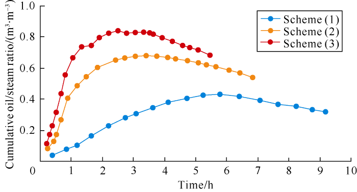
Fig. 10.
Comparison of cumulative oil/steam ratios of SAGD and ES-SAGD.
4. Conclusions
The oil viscosity reduction ratios of light hydrocarbon solvents to crude oil in descending order are: n-hexane, heptane, naphtha, xylene, diesel, and pentane, and the oil viscosity reduction ratio can reach 96.5% by adding 5% n-hexane into the oil at 50 °C.
Steam combined with light hydrocarbon solvent (10% in the experiment) has the dual effect on oil viscosity reduction by solvent dissolution and high temperature steam, which can enhance the lateral expansion rate of steam chamber, the oil drainage rate and the oil recovery factor.
Adding 1% xylene into the steam-solvent can dissolve asphaltene, reduce asphaltene precipitation and thus flow resistance, and further enhance the oil recovery factor.
The ES-SAGD using recycled solvent can realize the goal of replacing large amount of steam with a small portion of solvent, although slightly higher in cost currently, it has the advantages of enhancing oil drainage rate, shortening production period and enhancing oil recovery factor, and thus has huge application potential.
The ES-SAGD theoretical model by modifying the SAGD model based on the oil viscosity reduction characteristics of solvents was validated by experiments and can be used to predict ES-SAGD production dynamics.
Nomenclature
B3—similarity coefficient, dimensionless;
g—gravity acceleration, 7.323 126×1010m/d2 (9.8m/s2);
h—model or prototype reservoir thickness, m;
i—component number of the mixed oil;
K—absolute permeability, m2;
L—horizontal length of the horizontal well, m;
m—index of the oil viscosity-temperature curve, dimensionless;
n—total number of components of solvent and crude oil in mixed oil, dimensionless;
q—oil production rate,m3/d;
t—time, d;
w—width of the model or reservoir, m;
xi—mole fraction of components in mixed oil, dimensionless;
yi—volumetric fraction of components in mixed oil, dimensionless;
α—thermal diffusivity, m2/d;
ΔSo—movable oil saturation, %;
μi—dynamic viscosity of components in mixed oil, mPa•s;
μmix—dynamic viscosity of mixed oil, mPa•s;
vmix—kinetic viscosity of mixed oil, m2/d;
ρi—mass density of components in mixed oil, g/cm3;
ρmix—mass density of mixed oil with solvents and crude oil, g/cm3;
ϕ——porosity, %.
Reference
Key parameters forecast model of injector wellbores during the dual-well SAGD process
Physical simulation of improving the uniformity of steam chamber growth in the steam assisted gravity drainage
Models of steam-assisted gravity drainage(SAGD) steam chamber expanding velocity in double horizontal wells and its application
Research on ES-SAGD technology
Air- SAGD technology for super-heavy oil reservoirs
Study on numerical simulation of expanding solvent-steam assisted gravity drainage
Solvent-aided steam-assisted gravity drainage in thin oil sand reservoirs
DOI:10.1016/j.petrol.2010.09.003 URL [Cited within: 1]
Laboratory experimental testing and development of an efficient low pressure ES-SAGD process
Steam-solvent coinjection under reservoir heterogeneity: Should ES-SAGD be implemented for highly heterogeneous reservoirs
Semi-analytical modeling of steam-solvent gravity drainage of heavy oil and bitumen: Steady state model with linear interface
DOI:10.1016/j.fuel.2016.06.096 URL [Cited within: 1]
Efficient oil displacement near the chamber edge in ES-SAGD
DOI:10.1016/j.petrol.2014.04.007
URL
[Cited within: 1]

Steam-assisted gravity drainage (SAGD) is the most widely used method for in-situ bitumen recovery. Expanding-solvent-SAGD (ES-SAGD) has been proposed as an alternative to SAGD to improve its efficiency. In ES-SAGD, steam is coinjected with a small amount of solvent. Detailed oil recovery mechanisms near the chamber edge are little known due to the complex interaction of fluid and energy flow, and phase behavior. Prior research on ES-SAGD explains that coinjected solvent can further decrease oil viscosity near the chamber edge by dilution, in conjunction with heat.
In this paper, we conduct a detailed investigation on oil displacement mechanisms and the placement of solvent near the chamber edge using fine-scale reservoir simulation. The importance of properly considering both phase behavior and flow to design ES-SAGD is demonstrated. Results show that ES-SAGD can achieve a higher displacement efficiency than SAGD. Oil production rate in ES-SAGD can be two times higher than that in SAGD. As a result, the ultimate oil recovery of ES-SAGD is enhanced by almost 20%, compared to SAGD in this research. The oil saturation reduction results from condensed solvent bank and phase transition near the chamber edge. The condensed solvent bank lowers the oil-component concentrations there. The diluted oil with solvent is then redistributed in the gaseous and oleic phases in the presence of the water phase on the phase transition at the chamber edge. The resulting amount of the oleic phase can be significantly small, yielding lowered oil saturations in the ES-SAGD chamber. (C) 2014 Elsevier B.V.
Experimental study of co-injection of potential solvents with steam to enhance SAGD process
Solvent-assisted start-up of SAGD in shallow heavy oil reservoirs
Viscosity measurement and modeling for mixtures of Athabasca bitumen/hexane
Measurement and modeling of density and viscosity for mixtures of Athabasca bitumen and heavy n-alkane
Oil phase viscosity behavior in expanding-solvent steam-assisted gravity drainage
Modeling and measurement of thermo-physical properties for Athabasca bitumen and n-heptane mixtures
DOI:10.1016/j.fuel.2015.04.032 URL [Cited within: 1]
Reliable characterization of bitumen based on perturbation from n-alkanes for steam-solvent coinjection simulation
Prediction of SAGD production of ultra-heavy oil in Xinjiang F-oilfield
Steam chamber evolution during SAGD and ES-SAGD in thin layer oil sand reservoirs using a 2-D scaled model
Analysis of steam-solvent-bitumen phase behavior and solvent mass transfer for improving the performance of the ES-SAGD process
DOI:10.1016/j.petrol.2015.04.005 URL [Cited within: 1]
Asphaltene precipitation during bitumen extraction with expanding-solvent steam-assisted gravity drainage: Effects on pore-scale displacement
DOI:10.2118/170013-PA URL [Cited within: 1]
