National Natural Science Foundation of China. 51991363 National Natural Science Foundation of China. 51974350 Key Special Project for Introduced Talents Team of Southern Marine Science and Engineering Guangdong Laboratory (Guangzhou). GML2019ZD0501 Changjiang Scholars Program. Q2016135
Abstract
Based on the research of the formation mechanism and evolution rule of hydrate flow obstacle during deep-water gas well testing, a new method for the prevention of hydrate flow obstacle based on safety testing window is proposed by changing the previous idea of "preventing formation" to the idea of "allowing formation, preventing plugging". The results show that the effective inner diameter of the testing tubing and the wellhead pressure decrease gradually with the formation and precipitation of hydrates during deep-water gas well testing, and it presents three typical processes of slow, fast and sudden changes. There is a safety testing window during deep-water gas well testing. The safety testing window of deep-water gas well testing decreases first and then increases with the increase of gas production rate, and increases with the increase of hydrate inhibitor concentrations. In the case with different testing production rates, a reasonable testing order with alternate low and high gas production rates has been proposed to further reduce the dosage of hydrate inhibitor and even avoid the use of hydrate inhibitors considering the decomposition and fall-off of hydrates. Compared with the traditional methods, the new method based on safety testing window can reduce the dosage of hydrate inhibitor by more than 50%.
Keywords:deep-water gas well
;
gas well testing
;
hydrate
;
flow obstacle
;
safety testing window
;
hydrate inhibitor
ZHANG Jianbo, WANG Zhiyuan, LIU Shujie, MENG Wenbo, SUN Baojiang, SUN Jinsheng, WANG Jintang. A method for preventing hydrates from blocking flow during deep-water gas well testing. [J], 2020, 47(6): 1354-1362 doi:10.1016/S1876-3804(20)60143-X
Introduction
China has found many deep-water gas fields with abundant reserves, such as LS 17-2, 25-1, 18-1, etc.[1,2,3,4] During the development of deep-water gas field, gas well testing is an indispensable process[5]. Owing to the low-temperature and high-pressure conditions in deep water, deep-water gas well testing faces serious flow safety problems resulted by the formation of natural gas hydrate[6,7]. Gas hydrates are a kind of ice-like white solid formed by the contact of gas and water under certain temperature and pressure[8,9,10]. When hydrate generation occurs in the test string, it will migrate with fluid flow and deposit on the inner wall, thus reducing the effective inner diameter of the string[11,12,13], resulting in hydrate flow obstacle. Hydrate flow obstacle during deep-water gas well testing will seriously affect the testing process, resulting in high test cost and poor accuracy in evaluation of gas reservoir. In serious cases, the string may be completely blocked, and even cause safety accidents[14,15]. Some hydrate accidents have occurred during deep-water testing in the world, and caused serious results[16,17,18,19]. In 2017, the second offshore gas hydrate test production of Japan was forced to be interrupted twice due to secondary generation of hydrate, which seriously affected the trial production progress[20]. How to effectively prevent and control gas hydrate flow obstacle is an important work for deep-water gas well testing.
Up to now, the commonly used prevention method for hydrates is injecting chemicals, including thermodynamic inhibitors, kinetic inhibitors and anti-agglomerant inhibitors[21]. Thermodynamic inhibitors mainly reduce the equilibrium temperature and increase the equilibrium pressure of hydrate formation by changing the thermodynamic conditions of hydrates formed by water and hydrocarbon molecules. The commonly used thermodynamic inhibitors can be divided into alcohols (methanol, glycol, diethylene glycol, etc.) and salts (sodium chloride, potassium chloride, calcium chloride)[22,23]. Kinetic inhibitors mainly affect the crystallization process of hydrates, delay the formation time of hydrates and slow down the growth rate. The existing kinetic inhibitors include amide polymer and ketone polymer, etc.[24,25,26] Anti-agglomerant inhibitors are some polymers and surfactants, which mainly act as emulsifiers[27]. The commonly used anti-agglomerant inhibitors include quaternary ammonium salts of bromide, alkyl aromatic sulfonates, and alkyl polyglycosides, etc. Due to the characteristics of different inhibitors, thermodynamic and kinetic inhibitors are basically suitable for most of the hydrate prevention situations, while anti-agglomerant inhibitors are mainly used in oil-gas mixed transportation process. At present, the most commonly used hydrate prevention and management method during deep-water gas well testing is to inject excessive thermodynamic inhibitors to totally avoid hydrate formation, which has the disadvantages of large dosage of inhibitor, high cost and high requirements for injection equipment, etc.
Many scholars in China and abroad have studied the formation and prevention methods of hydrate flow obstacle. Based on experimental studies, Lingelem et al.[28] and Sloan et al.[9] proposed a hydrate-plug formation mechanism based on the growth and shedding of hydrate layers on the inner walls of a pipeline. Di Lorenzo et al.[29], Ding et al.[30], and Song et al.[31] studied experimentally the features of hydrate formation in the loop, and analyzed the patterns of hydrate deposition and plug formation in various types of flows. Based on the assessment of hydrate deposition and blockage, Li and Liu et al.[12,15,32] investigated the methods for the prevention of hydrate plugs in the testing string of deep- water gas wells. In a pioneering study, Wang et al.[11,33-35] firstly constructed a dynamical model of hydrate formation, migration, settlement, and plug formation that accounts for the mass and heat transfer characteristics of liquid droplets and films in annular mist flows. Song et al.[36] carried out research on optimization of hydrate management strategy in deep-water gas well testing, and suggested that dynamic inhibitor injection can be applied to hydrate plug prevention in deep-water gas well testing.
In view of the limitations of the existing methods in the prevention of hydrates in deep-water gas well testing, it is urgent to carry out research on the efficient prevention methods of hydrate flow obstacles in deep-water gas well testing. Based on the study of formation mechanism of hydrate flow obstacle in deep water gas well testing, a method of hydrate flow obstacle prevention based on safety testing window is proposed in this paper. The research results of this paper have important guiding significance for the effective prevention of hydrate flow obstacle during deep-water gas well testing and offshore hydrate trail production.
1. Formation of hydrate flow obstacle during deep-water gas well testing
The formation of hydrate flow obstacle in the testing string of deep-water gas wells is the result of continuous hydrate generation and deposition. In order to carry out the efficient prevention of hydrate flow obstacle for deep water gas well testing, it is necessary to recognize the formation mechanism and evolution of hydrate flow obstacle. The formation process of hydrate flow obstacle in deep water gas well testing mainly includes the appearance of hydrate generation zone, hydrate generation, migration, deposition and hydrate layer buildup, etc. Each process is affected by different factors.
Researches on the formation of hydrate flow obstacle require the prediction of hydrate formation zone, which pertains to the calculation of equilibrium conditions of hydrate formation and the prediction of wellbore pressure and temperature. Currently, our study in this aspect is already relatively mature. For example, Wang and Zhang et al.[11, 37-38] constructed and improved the models for prediction of the temperature and pressure in deep-water wellbore, as well as the methods for the quantitative prediction of hydrate formation zone. In the present study, the hydrate formation zone in the testing string of deep-water gas wells is predicted using the theories and methods described in these papers.
During the testing of deep-water gas wells, large quantities of natural gas from the reservoir will flow at high rates within the test string, along with small amounts of water. As the free water exists as liquid films on the walls of the tube or liquid droplets in the gaseous phase, an annular mist flow will occur in the test string[39]. In an annular mist flow, hydrates will form from the liquid films on the inner wall of the tube and the liquid droplets in the gaseous phase once the temperature and pressure are amenable for hydrate formation. Wang et al.[33, 35] found that hydrates formed by liquid film will entirely stick to the walls of the tube because of their immense adhesive strength. However, hydrate particles in the gaseous phase will not fully deposit on the walls, as some of these particles will instead be entrained by the high-velocity gas. In addition, some hydrate particles in the gaseous phase that settled in the liquid film could be returned to the gaseous phase by disturbances that atomize the film. Therefore, an effective deposition coefficient, S, is used to characterize the adherence of hydrate particles in the gaseous phase to the walls[33]. S is the ratio between the number of hydrate particles in the gaseous phase that adhere to the walls and the number of hydrate particles that migrate to the liquid film. The rate of formation and deposition of hydrates in an annular mist flow is given by the following equation:
The continuous formation and deposition of hydrates will eventually form a growing layer of hydrates on the inner walls of the string, which gradually narrows its effective flow area. The effective inner diameter of a tube at different position and time is calculated using the following expression:
A decrease in the inner diameter will inhibit flows within the pipeline and increase fluid pressure drop. In the presence of hydrate formation and deposition, the total pressure drop of a vertical pipeline is largely attributed to friction, gravity, and throttling (i.e., throttling due to changes in effective diameter). Therefore, the fluid pressure drop of the testing string with hydrate layer buildup is expressed as[40]:
Taking a deep-water gas well X (vertical well) as an example, the formation process of hydrate flow obstacle during well testing process is analyzed. In Well X, the water depth was 1447 m, well depth was 3474 m, the average reservoir temperature was 91 °C, average reservoir pressure was 38.7 MPa, mudline temperature was 3 °C, and the average sea surface temperature was 25 °C. The outer and inner diameters of the testing string were 4-1/2” and 3-3/8”, respectively, and the testing production rate was 20 - 100 × 104 m3/d. The composition of the produced gas is listed in Table 1, and the structure of the well is shown in Fig. 1.
Table 1
Table 1Components of the gas produced in deep-water gas well X.
On the basis of the prediction of hydrate formation zone during the testing process of the well X, a calculation of the rates of hydrate formation and deposition in the testing string can help determine the formation state of hydrate flow obstacle in the string. The hydrate layer in the testing string gradually grows owing to hydrate formation and deposition, and the variations in temperature and pressure distribution along the string result in varying hydrate formation and deposition rates. Because of this heterogeneity, there exists a specific location in the testing string that experiences the greatest shrinkage in inner diameter, and thus has the greatest risk for hydrate plug formation. Fig. 2 illustrates the time dependences of the dimensionless effective inner diameter (the ratio of the minimum effective inner diameter to the initial inner diameter in the string), fluid pressure drop, and wellhead pressure of well X when its gas and water production rates are 44 × 104 m3/d and 16 m3/d, respectively. The total pressure drop in the string increases with the buildup of the hydrate layer on its inner walls, which subsequently decreases the wellhead pressure. This is because shrinkages in the effective inner diameter of the string significantly increase the frictional pressure drop. In addition, a throttling effect will arise as the change in effective inner diameter varies from location to location, which further increases the total pressure drop in the string. Wellhead pressure is one of the few essential parameters that can be monitored in real time in the field. Therefore, a decrease in wellhead pressure during well testing with a constant production rate can be a critical sign of hydrate formation and deposition in the string. As shown in Fig. 2, the change in effective inner diameter can be divided into three regimes: slow-change, fast-change, and sudden-change regimes. In the slow-change regime, the effective inner diameter, pressure drop, and wellhead pressure generally change slowly (decrease, increase, and decrease, respectively) with hydrate formation and deposition. This regime has the longest persistence time among the three aforementioned regimes, and the fluid flows in the string are considered safe as long as this regime persists. However, when the effective inner diameter decreases to 60% of the original inner diameter, the slow-change regime changes into the fast-change regime. In this regime, the rate of shrinkage of the effective inner diameter increases significantly, which significantly increases pressure drop in the string and decreases the wellhead pressure, respectively. Subsequent changes in these parameters also become significant. Therefore, the fast- change regime marks a threshold for danger. Once the effective inner diameter of the string shrinks more than 40%, the fast- change regime changes into the sudden-change regime. At this point, the pressure drop and wellhead pressure of the string will rapidly increase and decrease, respectively. This regime persists for a very short time, and it is a danger zone where hydrate blockages are extremely likely to occur. Therefore, we chose the median time of the fast-change regime (50% inner diameter reduction) as the endpoint of the “safe” testing period, i.e., the safety testing window (STW). For example, the safety testing window of well X for a given test production rate of 44 × 104 m3/d is 7.86 h.
Fig. 2.
Evolution law of hydrate flow obstacle during deep- water gas well testing.
2. A prevention method for hydrate flow obstacle based on safety testing window
Based on the previous researches, it is suggested that not all of the hydrates that form in the testing string will settle on the inner walls, and that the formation of hydrate deposits will not necessarily lead to hydrate plugging. As a certain time is needed for the formation of hydrate plugging, a safety testing window exists. In this work, we propose a method for the prevention of hydrate flow obstacle on the basis of safety testing window. According to the different testing operations, it is divided into two methods, the prevention method of hydrate flow obstacle with a constant testing production rate and with variable testing production rates.
2.1. Prevention of hydrate flow obstacle with a constant testing production rate
The formation and evolution of hydrate flow obstacle during deep-water gas well testing depends on the testing production rate and the hydrate inhibitor concentration. Although the analysis in this study is based on the use of ethylene glycol, our flow assurance method remains applicable even with other alcohol inhibitors. The equilibrium temperatures and pressures of hydrate formation for well X, in the presence of different ethylene glycol concentrations (volume ratio of ethylene glycol to water), are shown in Fig. 3. It is observed that the hydrate equilibrium line shifts in the upper-left direction with increases in ethylene glycol concentrations. This implies that higher pressures and lower temperatures are required for hydrate formation at high ethylene glycol concentrations, which makes it harder for hydrates to form in the testing string.
Fig. 3.
Equilibrium temperature and pressure for hydrate formation at various ethylene glycol concentrations.
Fig. 4 illustrates the distribution of hydrate formation zones in the testing string with different ethylene glycol concentrations and gas production rates. The hydrate formation zone for a given production rate and inhibitor concentration is given by the area between the upper and lower end points of the curves in this figure. The hydrate formation zone shrinks with increases in testing production rate and inhibitor concentration. This is mostly because the temperature and pressure for hydrate formation in a testing string become increasingly rigorous with the increase in inhibitor concentration. Likewise, a rise in the production rate during testing will increase and decrease the temperature and pressure of the testing string, respectively; this impedes the formation of hydrates in the testing string. In addition, there exists a critical production rate during testing for each inhibitor concentration where the hydrate formation zone completely disappears. This critical rate decreases with increases in hydrate inhibitor concentration. For example, the critical production rates for ethylene glycol-to-water ratios of 0 and 0.5 are 62 × 104 m3/d and 40 × 104 m3/d, respectively.
Fig. 4.
Changes in the hydrate formation zone in the testing string with varying ethylene glycol concentrations.
By calculating the rates of hydrate formation and deposition in the string, the process of hydrate flow obstacle formation for each inhibitor concentration and testing production rate can be elucidated. Fig. 5 illustrates that the minimum effective inner diameter of test string first decreases and subsequently increases with an increase in testing production rate. This is because hydrate formation and deposition rates are jointly affected by temperature, pressure, and the area of gas- liquid contact. Meanwhile, a higher inhibitor concentration will cause a more significant increase in effective inner diameter. This is because of the following reasons: On one hand, the injection of hydrate inhibitors shrinks the hydrate formation zone in the string. On the other hand, the hydrate inhibitor decreases the rates of hydrate formation and deposition, which subsequently slows the buildup of the hydrate layer on the inner walls of the string. These effects reduce the rate of shrinkage of the effective inner diameter, which subsequently decreases the risk of hydrate flow obstacle formation. In addition, it is indicated that there is a risk of hydrate flow obstacle formation at testing production rates of 34 - 55 × 104 m3/d if the testing time is 9 h. However, the injection of a low concentration of inhibitor (i.e., an ethylene glycol-to-water ratio of 0.125:1) is sufficient to fully eliminate the risk of hydrate flow obstacle formation under these conditions.
Fig. 5.
Variations in the minimum effective inner diameter of the test string over time, with different ethylene glycol concentrations.
Fig. 6 illustrates the time dependences of the wellhead pressure of the string and total pressure drop at a testing production rate of 44 × 104 m3/d and varying ethylene glycol concentrations. It is observed that a rise in inhibitor concentration decreases the total pressure drop of the string at all testing times and significantly slows the decline in wellhead pressure. This is because the injection of a hydrate inhibitor decreases the rates of hydrate formation and deposition, which subsequently slows the shrinkage in the effective inner diameter of the string. This effectively decreases the pressure drop of the string and maintains the pressure of wellhead within a safe range for a longer duration.
Fig. 6.
Time dependences of wellhead pressure and total pressure drop with different ethylene glycol concentrations.
It can be inferred from the aforementioned results that the STW is the critical period before a hydrate flow obstacle is formed during a well testing. The requirements for normative gas well testing will always be met as long as the testing time is shorter than the STW. The changes in STW with varying inhibitor concentrations and testing production rates are shown in Fig. 7. It can be observed that the STW varies with testing production rate, and that the addition of a hydrate inhibitor at an appropriate concentration will significantly prolong the STW. Therefore, if the designed testing time is shorter than the STW that corresponds to the given testing production rate, it is unnecessary to inject hydrate inhibitors for flow assurance. However, if a hydrate flow obstacle can form during the designated testing time, a suitably low dose of hydrate inhibitors may then be injected to ensure that the testing process will be cost-efficient and completed safely. For example, given a testing production rate of 50 × 104 m3/d and testing time of 10 h, an ethylene-glycol-to-water ratio of 0.125 will be sufficient to prevent hydrate flow obstacle formation. In addition, the risk of hydrate flow obstacle formation in the testing string can be evaluated by the real-time monitoring of wellhead pressure in situ, to ensure flow assurance during deep-water gas well testing.
Fig. 7.
Changes in the STW due to varying ethylene glycol concentration and test production rates.
2.2. Prevention of hydrate flow obstacle with variable testing production rates
During deep-water gas well testing, it is often necessary to perform the well testing analysis with different testing production rates to accurately estimate the geological parameters, and the capacity of a reservoir, etc. In most cases, four different tests are performed with a gradually increasing rate of gas production[15], as shown in Table 2. Based on the previous information, a method for hydrate flow obstacle prevention where the testing production rate is varied in an alternating sequence of low and high rates of production is proposed in this work. The modified sequence is shown in Table 2, and it is observed that these changes help prevent continuous hydrate formation and deposition in a test string.
Table 2
Table 2Testing regime with varying testing production rates.
An increase in testing production rate will decrease the rate of heat loss from the high-temperature fluids in the testing string to its low-temperature environment, thus increasing its temperature and decreasing pressure. This effectively shrinks the hydrate formation zone within the testing string. Once the testing production rate exceeds a certain threshold, the conditions for hydrate formation will no longer be present throughout the testing string. If the positions in the string that originally meet the hydrate formation conditions is separated from the hydrate formation zone due to the increase of testing production rate, the hydrate layer that was deposited on the walls of the string will dissociate and gradually become thinner. The decomposition of the hydrate layer is mainly determined by the surface area and subcooling degree of hydrate decomposition. As the temperature, pressure, and hydrate layer thickness of the testing string varies at each position and time, the rate of hydrate decomposition also vary with time and position, which is given by the formula proposed by Goel et al.[41]:
By considering the time and location dependence of hydrate decomposition rates, the changes in the effective inner diameter of the string when the deposited hydrates on its inner wall begins to decompose is given by the following equation:
When the testing production rate changes from low to high, the gas velocity in the string increase suddenly, which means that the fluid shear force exerted on the hydrate layer increase accordingly. Once the fluid shear stress exerted on the hydrate layer is greater than the critical shear force for falling off, part of the hydrate layer will slough, as illustrated in Fig. 8. This lead to the effective inner diameter of the string increase accordingly, which will decrease the risk of hydrate flow obstacle. Hence, the influence of hydrate sloughing should be included in the calculation of the thickness of hydrate layer under variable testing gas production rates. Whether the hydrate layer at a certain position will fall off due to fluid shear stress can be determined by the following criteria proposed by Di Lorenzo et al.[42].
By calculating the temperature and pressure in the wellbore and the rates of hydrate formation, deposition, and decomposition in a conventional testing regime, the risk of hydrate flow obstacle in the testing string can be obtained in this testing regime. As seen in Fig. 9, it is observed that hydrate formation zones are always present in the test string during the first and second tests. This will lead to successive hydrate formation and deposition in the string, which gradually thickens the hydrate layer in the string and shrinks its minimum effective inner diameter. In the next two tests, the rise in testing production rate cause the temperature and pressure of the string to rise and fall, respectively. This causes the wellbore to fully vacate the hydrate formation zone. Consequently, the hydrate layer that had formed and adhered onto the wall of the string during the first two tests will gradually decompose (with the rate of hydrate decomposition increasing with production rate). However, the minimum effective inner diameter of the testing string during the first two tests will exceed the critical threshold for the formation of hydrate flow obstacle. This explains why the conventional well testing regime is often susceptible to hydrate flow obstacle.
Fig. 9.
Changes in the hydrate formation zone and minimum effective inner diameter under the conventional testing regime.
As shown in Fig. 10, under the “alternating” testing regime, hydrate formation zones exist in the testing string in the first and third tests, but totally disappear in the second and fourth. Thus, the hydrate formation zone is not allowed to persist for a long, continuous period, which helps minimize the risk of flow obstacle in the testing string. The hydrate layer that deposited on the wall of the string during a low-production-rate testing will decompose in the next high-production-rate testing due to increases in temperature and decrease in pressure. Furthermore, the abrupt change in production rate that occurs between the first and third tests and the second and fourth tests will cause a few hydrate layers to fall off, which then leads to a sudden increase in effective inner diameter. These effects jointly ensure that the minimum effective inner diameter of the testing string will stay above the critical value for hydrate flow obstacle. As compared to the conventional regime, the proposed “alternating” testing regime increases the minimum dimensionless effective diameter to 0.74. From Fig. 10, it is also seen that if hydrate inhibitor (the ethylene-glycol-to-water ratio is 0.125) is injected under the condition of “alternating” testing regime, the minimum dimensionless effective inner diameter of the string will be further increased to 0.85. This shows that the risk of hydrate flow obstacle in the testing string will be further reduced if the low concentration hydrate inhibitor is injected under dangerous testing production rates, which further improve the effectiveness and practicability of the proposed method. Therefore, the risk of hydrate flow obstacle in the string can be effectively reduced by reasonably changing the “alternating” testing regime with low and high production rates. The effectiveness and practicability of this method can be further improved by adding low concentration inhibitor injection. Compared with the traditional hydrate prevention method, this method can greatly reduce the needed amount of hydrate inhibitors, and even may not need to inject inhibitors at all.
Fig. 10.
Changes in the hydrate formation zone and minimum effective inner diameter under the “alternating” testing regime.
Table 3 shows a comparison of inhibitor dosage of different prevention methods under the condition that the designed testing time of 15h. Compared with the conventional hydrate prevention method, the proposed method based on STW can reduce the dosage of hydrate inhibitor by more than 50%. Hence, this method has the potential to become highly effective and cost-efficient prevention method for hydrate flow obstacle during deep-water gas well testing. This method is mainly aimed at the normal testing process with long duration and large inhibitor consumption. For the initial well opening and well cleaning stages of deep-water gas wells, it is not recommended to use this method to prevent hydrate flow obstacle due to the short duration and complex process.
Table 3
Table 3Comparison of hydrate inhibitor dosage for different hydrate prevention methods.
Continuous hydrate formation and deposition in a testing string will gradually decrease the effective inner diameter and wellhead pressure of a test string. These changes exhibit three typical processes, i.e., slow-change, fast-change and sudden-change, and there exists safety testing window (STW). The risk of hydrate flow obstacle in the testing string increases with testing time, decreases with increases in hydrate inhibitor concentration, and first increases and subsequently decreases with a rise in gas production rate.
The STW is an important parameter for the prevention of hydrate flow obstacle in deep-water gas well testing, and the length of the STW depends on inhibitor concentration and testing production rate. Given a fixed testing production rate, hydrate inhibitors are not necessary if the testing time is shorter than the corresponding STW. If the testing time exceeds the STW, a low concentration of hydrate inhibitor can be injected to prolong the STW and ensure flow assurance throughout the testing. Under variable testing production rates, a testing regime with different production rates that are alternatingly low and high will increase the minimum dimensionless effective inner diameter of the testing string, thus preventing the formation of hydrate flow obstacle, even in the absence of hydrate inhibitors. Supplementing this method with a low- concentration injection of hydrate inhibitors should further enhance its effectiveness in ensuring flow assurance.
The proposed STW-based hydrate flow obstacle prevention method obviously decrease the needed amount of hydrate inhibitor required for normal testing process of deep-water gas wells. Therefore, this method has the potential to become highly effective and cost-efficient prevention method for hydrate flow obstacle during deep-water gas well testing.
Nomenclature
Ads—hydrate decomposition surface area, m2;
Agf—gas-liquid contact area, m2;
Ap—inner cross section of string, m2;
Che—mass concentration of hydrate particles in the gas phase, kg/m3;
Cle—mass concentration of liquid droplets in the gas phase, kg/m3;
It is essential to consider the thermodynamics, temperature, and pressure conditions of gas hydrate formation in order to predict the gas hydrate formation region in the wellbore of deepwater drilling. Multiphase flow governing equations (including continuity equation and momentum conservation equation), temperature field equations in annulus and drill pipe, and hydrate formation thermodynamics equation are established based on the characteristics of deepwater drilling. The definite conditions, discrete methods, and iterative steps are given to solve the equations under different working conditions. Through examples of calculation, the impacts of relevant parameters on gas hydrate formation region during drilling, off drilling, and well killing process are discussed. The result shows that the hydrate formation region is getting small when circulation volume becomes great, inhibitor concentration becomes high, downtime becomes short, or choke line size becomes large. And the result also indicates that it is more efficient to consider multifactors to suppress hydrate formation. The parameters can be optimized based on the method.
LIZhong, YANGJin, WANGErjun, et al.
A study of prevention and control of hydrates During well testing in wells with high temperature and high pressure
Wellbore temperature field equations are established with considerations of the enthalpy changes of the natural gas during the deep-water gas well testing. A prediction method for the natural gas hydrate formation region during the deep-water gas well testing is proposed, which combines the wellbore temperature field equations, the phase equilibrium conditions of the natural gas hydrate formation and the calculation methods for the pressure field. Through the sensitivity analysis of the parameters that affect the hydrate formation region, it can be concluded that during the deep-water gas well testing, with the reduction of the gas production rate and the decrease of the geothermal gradient, along with the increase of the depth of water, the hydrate formation region in the wellbore enlarges, the hydrate formation regions differ with different component contents of natural gases, as compared with the pure methane gas, with the increase of ethane and propane, the hydrate formation region expands, the admixture of inhibitors, the type and the concentrations of which can be optimized through the method proposed in the paper, will reduce the hydrate formation region, the throttling effect will lead to the abrupt changes of temperature and pressure, which results in a variation of the hydrate formation region, if the throttling occurs in the shallow part of the wellbore, the temperature will drop too much, which enlarges the hydrate formation region, otherwise, if the throttling occurs in the deep part of the wellbore, the hydrate formation region will be reduced due to the decrease of the pressure.
ZHANGJianbo, WANGZhiyuan, SUNBaojiang, et al.
An integrated prediction model of hydrate blockage formation in deep-water gas wells
International Journal of Heat and Mass Transfer, 2019,140:187-202.
Gas hydrate risks and prevention for deep water drilling and completion: A case study of well QDN-X in Qiongdongnan Basin, South China Sea
1
2014
... China has found many deep-water gas fields with abundant reserves, such as LS 17-2, 25-1, 18-1, etc.[1,2,3,4] During the development of deep-water gas field, gas well testing is an indispensable process[5]. Owing to the low-temperature and high-pressure conditions in deep water, deep-water gas well testing faces serious flow safety problems resulted by the formation of natural gas hydrate[6,7]. Gas hydrates are a kind of ice-like white solid formed by the contact of gas and water under certain temperature and pressure[8,9,10]. When hydrate generation occurs in the test string, it will migrate with fluid flow and deposit on the inner wall, thus reducing the effective inner diameter of the string[11,12,13], resulting in hydrate flow obstacle. Hydrate flow obstacle during deep-water gas well testing will seriously affect the testing process, resulting in high test cost and poor accuracy in evaluation of gas reservoir. In serious cases, the string may be completely blocked, and even cause safety accidents[14,15]. Some hydrate accidents have occurred during deep-water testing in the world, and caused serious results[16,17,18,19]. In 2017, the second offshore gas hydrate test production of Japan was forced to be interrupted twice due to secondary generation of hydrate, which seriously affected the trial production progress[20]. How to effectively prevent and control gas hydrate flow obstacle is an important work for deep-water gas well testing. ...
Accumulation mechanism of LS 17-2 deep water gas field in Qiongdongnan Basin
1
2016
... China has found many deep-water gas fields with abundant reserves, such as LS 17-2, 25-1, 18-1, etc.[1,2,3,4] During the development of deep-water gas field, gas well testing is an indispensable process[5]. Owing to the low-temperature and high-pressure conditions in deep water, deep-water gas well testing faces serious flow safety problems resulted by the formation of natural gas hydrate[6,7]. Gas hydrates are a kind of ice-like white solid formed by the contact of gas and water under certain temperature and pressure[8,9,10]. When hydrate generation occurs in the test string, it will migrate with fluid flow and deposit on the inner wall, thus reducing the effective inner diameter of the string[11,12,13], resulting in hydrate flow obstacle. Hydrate flow obstacle during deep-water gas well testing will seriously affect the testing process, resulting in high test cost and poor accuracy in evaluation of gas reservoir. In serious cases, the string may be completely blocked, and even cause safety accidents[14,15]. Some hydrate accidents have occurred during deep-water testing in the world, and caused serious results[16,17,18,19]. In 2017, the second offshore gas hydrate test production of Japan was forced to be interrupted twice due to secondary generation of hydrate, which seriously affected the trial production progress[20]. How to effectively prevent and control gas hydrate flow obstacle is an important work for deep-water gas well testing. ...
Establishment and application of a wellbore temperature field prediction model for deep water gas well testing
1
2016
... China has found many deep-water gas fields with abundant reserves, such as LS 17-2, 25-1, 18-1, etc.[1,2,3,4] During the development of deep-water gas field, gas well testing is an indispensable process[5]. Owing to the low-temperature and high-pressure conditions in deep water, deep-water gas well testing faces serious flow safety problems resulted by the formation of natural gas hydrate[6,7]. Gas hydrates are a kind of ice-like white solid formed by the contact of gas and water under certain temperature and pressure[8,9,10]. When hydrate generation occurs in the test string, it will migrate with fluid flow and deposit on the inner wall, thus reducing the effective inner diameter of the string[11,12,13], resulting in hydrate flow obstacle. Hydrate flow obstacle during deep-water gas well testing will seriously affect the testing process, resulting in high test cost and poor accuracy in evaluation of gas reservoir. In serious cases, the string may be completely blocked, and even cause safety accidents[14,15]. Some hydrate accidents have occurred during deep-water testing in the world, and caused serious results[16,17,18,19]. In 2017, the second offshore gas hydrate test production of Japan was forced to be interrupted twice due to secondary generation of hydrate, which seriously affected the trial production progress[20]. How to effectively prevent and control gas hydrate flow obstacle is an important work for deep-water gas well testing. ...
Theory, technology and prospects of conventional and unconventional natural gas
1
2018
... China has found many deep-water gas fields with abundant reserves, such as LS 17-2, 25-1, 18-1, etc.[1,2,3,4] During the development of deep-water gas field, gas well testing is an indispensable process[5]. Owing to the low-temperature and high-pressure conditions in deep water, deep-water gas well testing faces serious flow safety problems resulted by the formation of natural gas hydrate[6,7]. Gas hydrates are a kind of ice-like white solid formed by the contact of gas and water under certain temperature and pressure[8,9,10]. When hydrate generation occurs in the test string, it will migrate with fluid flow and deposit on the inner wall, thus reducing the effective inner diameter of the string[11,12,13], resulting in hydrate flow obstacle. Hydrate flow obstacle during deep-water gas well testing will seriously affect the testing process, resulting in high test cost and poor accuracy in evaluation of gas reservoir. In serious cases, the string may be completely blocked, and even cause safety accidents[14,15]. Some hydrate accidents have occurred during deep-water testing in the world, and caused serious results[16,17,18,19]. In 2017, the second offshore gas hydrate test production of Japan was forced to be interrupted twice due to secondary generation of hydrate, which seriously affected the trial production progress[20]. How to effectively prevent and control gas hydrate flow obstacle is an important work for deep-water gas well testing. ...
Prediction of wax precipitation region in wellbore during deep water oil well testing
1
2018
... China has found many deep-water gas fields with abundant reserves, such as LS 17-2, 25-1, 18-1, etc.[1,2,3,4] During the development of deep-water gas field, gas well testing is an indispensable process[5]. Owing to the low-temperature and high-pressure conditions in deep water, deep-water gas well testing faces serious flow safety problems resulted by the formation of natural gas hydrate[6,7]. Gas hydrates are a kind of ice-like white solid formed by the contact of gas and water under certain temperature and pressure[8,9,10]. When hydrate generation occurs in the test string, it will migrate with fluid flow and deposit on the inner wall, thus reducing the effective inner diameter of the string[11,12,13], resulting in hydrate flow obstacle. Hydrate flow obstacle during deep-water gas well testing will seriously affect the testing process, resulting in high test cost and poor accuracy in evaluation of gas reservoir. In serious cases, the string may be completely blocked, and even cause safety accidents[14,15]. Some hydrate accidents have occurred during deep-water testing in the world, and caused serious results[16,17,18,19]. In 2017, the second offshore gas hydrate test production of Japan was forced to be interrupted twice due to secondary generation of hydrate, which seriously affected the trial production progress[20]. How to effectively prevent and control gas hydrate flow obstacle is an important work for deep-water gas well testing. ...
Prediction of gas hydrate formation region in the wellbore of deepwater drilling
1
2008
... China has found many deep-water gas fields with abundant reserves, such as LS 17-2, 25-1, 18-1, etc.[1,2,3,4] During the development of deep-water gas field, gas well testing is an indispensable process[5]. Owing to the low-temperature and high-pressure conditions in deep water, deep-water gas well testing faces serious flow safety problems resulted by the formation of natural gas hydrate[6,7]. Gas hydrates are a kind of ice-like white solid formed by the contact of gas and water under certain temperature and pressure[8,9,10]. When hydrate generation occurs in the test string, it will migrate with fluid flow and deposit on the inner wall, thus reducing the effective inner diameter of the string[11,12,13], resulting in hydrate flow obstacle. Hydrate flow obstacle during deep-water gas well testing will seriously affect the testing process, resulting in high test cost and poor accuracy in evaluation of gas reservoir. In serious cases, the string may be completely blocked, and even cause safety accidents[14,15]. Some hydrate accidents have occurred during deep-water testing in the world, and caused serious results[16,17,18,19]. In 2017, the second offshore gas hydrate test production of Japan was forced to be interrupted twice due to secondary generation of hydrate, which seriously affected the trial production progress[20]. How to effectively prevent and control gas hydrate flow obstacle is an important work for deep-water gas well testing. ...
A study of prevention and control of hydrates During well testing in wells with high temperature and high pressure
1
2011
... China has found many deep-water gas fields with abundant reserves, such as LS 17-2, 25-1, 18-1, etc.[1,2,3,4] During the development of deep-water gas field, gas well testing is an indispensable process[5]. Owing to the low-temperature and high-pressure conditions in deep water, deep-water gas well testing faces serious flow safety problems resulted by the formation of natural gas hydrate[6,7]. Gas hydrates are a kind of ice-like white solid formed by the contact of gas and water under certain temperature and pressure[8,9,10]. When hydrate generation occurs in the test string, it will migrate with fluid flow and deposit on the inner wall, thus reducing the effective inner diameter of the string[11,12,13], resulting in hydrate flow obstacle. Hydrate flow obstacle during deep-water gas well testing will seriously affect the testing process, resulting in high test cost and poor accuracy in evaluation of gas reservoir. In serious cases, the string may be completely blocked, and even cause safety accidents[14,15]. Some hydrate accidents have occurred during deep-water testing in the world, and caused serious results[16,17,18,19]. In 2017, the second offshore gas hydrate test production of Japan was forced to be interrupted twice due to secondary generation of hydrate, which seriously affected the trial production progress[20]. How to effectively prevent and control gas hydrate flow obstacle is an important work for deep-water gas well testing. ...
The status of the kinetics of hydrate nucleation
1
2001
... China has found many deep-water gas fields with abundant reserves, such as LS 17-2, 25-1, 18-1, etc.[1,2,3,4] During the development of deep-water gas field, gas well testing is an indispensable process[5]. Owing to the low-temperature and high-pressure conditions in deep water, deep-water gas well testing faces serious flow safety problems resulted by the formation of natural gas hydrate[6,7]. Gas hydrates are a kind of ice-like white solid formed by the contact of gas and water under certain temperature and pressure[8,9,10]. When hydrate generation occurs in the test string, it will migrate with fluid flow and deposit on the inner wall, thus reducing the effective inner diameter of the string[11,12,13], resulting in hydrate flow obstacle. Hydrate flow obstacle during deep-water gas well testing will seriously affect the testing process, resulting in high test cost and poor accuracy in evaluation of gas reservoir. In serious cases, the string may be completely blocked, and even cause safety accidents[14,15]. Some hydrate accidents have occurred during deep-water testing in the world, and caused serious results[16,17,18,19]. In 2017, the second offshore gas hydrate test production of Japan was forced to be interrupted twice due to secondary generation of hydrate, which seriously affected the trial production progress[20]. How to effectively prevent and control gas hydrate flow obstacle is an important work for deep-water gas well testing. ...
2
2011
... China has found many deep-water gas fields with abundant reserves, such as LS 17-2, 25-1, 18-1, etc.[1,2,3,4] During the development of deep-water gas field, gas well testing is an indispensable process[5]. Owing to the low-temperature and high-pressure conditions in deep water, deep-water gas well testing faces serious flow safety problems resulted by the formation of natural gas hydrate[6,7]. Gas hydrates are a kind of ice-like white solid formed by the contact of gas and water under certain temperature and pressure[8,9,10]. When hydrate generation occurs in the test string, it will migrate with fluid flow and deposit on the inner wall, thus reducing the effective inner diameter of the string[11,12,13], resulting in hydrate flow obstacle. Hydrate flow obstacle during deep-water gas well testing will seriously affect the testing process, resulting in high test cost and poor accuracy in evaluation of gas reservoir. In serious cases, the string may be completely blocked, and even cause safety accidents[14,15]. Some hydrate accidents have occurred during deep-water testing in the world, and caused serious results[16,17,18,19]. In 2017, the second offshore gas hydrate test production of Japan was forced to be interrupted twice due to secondary generation of hydrate, which seriously affected the trial production progress[20]. How to effectively prevent and control gas hydrate flow obstacle is an important work for deep-water gas well testing. ...
... Many scholars in China and abroad have studied the formation and prevention methods of hydrate flow obstacle. Based on experimental studies, Lingelem et al.[28] and Sloan et al.[9] proposed a hydrate-plug formation mechanism based on the growth and shedding of hydrate layers on the inner walls of a pipeline. Di Lorenzo et al.[29], Ding et al.[30], and Song et al.[31] studied experimentally the features of hydrate formation in the loop, and analyzed the patterns of hydrate deposition and plug formation in various types of flows. Based on the assessment of hydrate deposition and blockage, Li and Liu et al.[12,15,32] investigated the methods for the prevention of hydrate plugs in the testing string of deep- water gas wells. In a pioneering study, Wang et al.[11,33-35] firstly constructed a dynamical model of hydrate formation, migration, settlement, and plug formation that accounts for the mass and heat transfer characteristics of liquid droplets and films in annular mist flows. Song et al.[36] carried out research on optimization of hydrate management strategy in deep-water gas well testing, and suggested that dynamic inhibitor injection can be applied to hydrate plug prevention in deep-water gas well testing. ...
Investigation of rheological properties of methane hydrate slurry with carboxmethylcellulose
1
2020
... China has found many deep-water gas fields with abundant reserves, such as LS 17-2, 25-1, 18-1, etc.[1,2,3,4] During the development of deep-water gas field, gas well testing is an indispensable process[5]. Owing to the low-temperature and high-pressure conditions in deep water, deep-water gas well testing faces serious flow safety problems resulted by the formation of natural gas hydrate[6,7]. Gas hydrates are a kind of ice-like white solid formed by the contact of gas and water under certain temperature and pressure[8,9,10]. When hydrate generation occurs in the test string, it will migrate with fluid flow and deposit on the inner wall, thus reducing the effective inner diameter of the string[11,12,13], resulting in hydrate flow obstacle. Hydrate flow obstacle during deep-water gas well testing will seriously affect the testing process, resulting in high test cost and poor accuracy in evaluation of gas reservoir. In serious cases, the string may be completely blocked, and even cause safety accidents[14,15]. Some hydrate accidents have occurred during deep-water testing in the world, and caused serious results[16,17,18,19]. In 2017, the second offshore gas hydrate test production of Japan was forced to be interrupted twice due to secondary generation of hydrate, which seriously affected the trial production progress[20]. How to effectively prevent and control gas hydrate flow obstacle is an important work for deep-water gas well testing. ...
Modeling of hydrate blockage in gas-dominated systems
3
2016
... China has found many deep-water gas fields with abundant reserves, such as LS 17-2, 25-1, 18-1, etc.[1,2,3,4] During the development of deep-water gas field, gas well testing is an indispensable process[5]. Owing to the low-temperature and high-pressure conditions in deep water, deep-water gas well testing faces serious flow safety problems resulted by the formation of natural gas hydrate[6,7]. Gas hydrates are a kind of ice-like white solid formed by the contact of gas and water under certain temperature and pressure[8,9,10]. When hydrate generation occurs in the test string, it will migrate with fluid flow and deposit on the inner wall, thus reducing the effective inner diameter of the string[11,12,13], resulting in hydrate flow obstacle. Hydrate flow obstacle during deep-water gas well testing will seriously affect the testing process, resulting in high test cost and poor accuracy in evaluation of gas reservoir. In serious cases, the string may be completely blocked, and even cause safety accidents[14,15]. Some hydrate accidents have occurred during deep-water testing in the world, and caused serious results[16,17,18,19]. In 2017, the second offshore gas hydrate test production of Japan was forced to be interrupted twice due to secondary generation of hydrate, which seriously affected the trial production progress[20]. How to effectively prevent and control gas hydrate flow obstacle is an important work for deep-water gas well testing. ...
... Many scholars in China and abroad have studied the formation and prevention methods of hydrate flow obstacle. Based on experimental studies, Lingelem et al.[28] and Sloan et al.[9] proposed a hydrate-plug formation mechanism based on the growth and shedding of hydrate layers on the inner walls of a pipeline. Di Lorenzo et al.[29], Ding et al.[30], and Song et al.[31] studied experimentally the features of hydrate formation in the loop, and analyzed the patterns of hydrate deposition and plug formation in various types of flows. Based on the assessment of hydrate deposition and blockage, Li and Liu et al.[12,15,32] investigated the methods for the prevention of hydrate plugs in the testing string of deep- water gas wells. In a pioneering study, Wang et al.[11,33-35] firstly constructed a dynamical model of hydrate formation, migration, settlement, and plug formation that accounts for the mass and heat transfer characteristics of liquid droplets and films in annular mist flows. Song et al.[36] carried out research on optimization of hydrate management strategy in deep-water gas well testing, and suggested that dynamic inhibitor injection can be applied to hydrate plug prevention in deep-water gas well testing. ...
... Researches on the formation of hydrate flow obstacle require the prediction of hydrate formation zone, which pertains to the calculation of equilibrium conditions of hydrate formation and the prediction of wellbore pressure and temperature. Currently, our study in this aspect is already relatively mature. For example, Wang and Zhang et al.[11, 37-38] constructed and improved the models for prediction of the temperature and pressure in deep-water wellbore, as well as the methods for the quantitative prediction of hydrate formation zone. In the present study, the hydrate formation zone in the testing string of deep-water gas wells is predicted using the theories and methods described in these papers. ...
Research on evaluation method of wellbore hydrate blocking degree during deepwater gas well testing
2
2018
... China has found many deep-water gas fields with abundant reserves, such as LS 17-2, 25-1, 18-1, etc.[1,2,3,4] During the development of deep-water gas field, gas well testing is an indispensable process[5]. Owing to the low-temperature and high-pressure conditions in deep water, deep-water gas well testing faces serious flow safety problems resulted by the formation of natural gas hydrate[6,7]. Gas hydrates are a kind of ice-like white solid formed by the contact of gas and water under certain temperature and pressure[8,9,10]. When hydrate generation occurs in the test string, it will migrate with fluid flow and deposit on the inner wall, thus reducing the effective inner diameter of the string[11,12,13], resulting in hydrate flow obstacle. Hydrate flow obstacle during deep-water gas well testing will seriously affect the testing process, resulting in high test cost and poor accuracy in evaluation of gas reservoir. In serious cases, the string may be completely blocked, and even cause safety accidents[14,15]. Some hydrate accidents have occurred during deep-water testing in the world, and caused serious results[16,17,18,19]. In 2017, the second offshore gas hydrate test production of Japan was forced to be interrupted twice due to secondary generation of hydrate, which seriously affected the trial production progress[20]. How to effectively prevent and control gas hydrate flow obstacle is an important work for deep-water gas well testing. ...
... Many scholars in China and abroad have studied the formation and prevention methods of hydrate flow obstacle. Based on experimental studies, Lingelem et al.[28] and Sloan et al.[9] proposed a hydrate-plug formation mechanism based on the growth and shedding of hydrate layers on the inner walls of a pipeline. Di Lorenzo et al.[29], Ding et al.[30], and Song et al.[31] studied experimentally the features of hydrate formation in the loop, and analyzed the patterns of hydrate deposition and plug formation in various types of flows. Based on the assessment of hydrate deposition and blockage, Li and Liu et al.[12,15,32] investigated the methods for the prevention of hydrate plugs in the testing string of deep- water gas wells. In a pioneering study, Wang et al.[11,33-35] firstly constructed a dynamical model of hydrate formation, migration, settlement, and plug formation that accounts for the mass and heat transfer characteristics of liquid droplets and films in annular mist flows. Song et al.[36] carried out research on optimization of hydrate management strategy in deep-water gas well testing, and suggested that dynamic inhibitor injection can be applied to hydrate plug prevention in deep-water gas well testing. ...
Prediction of hydrate deposition in pipelines to improve gas transportation efficiency and safety
1
2019
... China has found many deep-water gas fields with abundant reserves, such as LS 17-2, 25-1, 18-1, etc.[1,2,3,4] During the development of deep-water gas field, gas well testing is an indispensable process[5]. Owing to the low-temperature and high-pressure conditions in deep water, deep-water gas well testing faces serious flow safety problems resulted by the formation of natural gas hydrate[6,7]. Gas hydrates are a kind of ice-like white solid formed by the contact of gas and water under certain temperature and pressure[8,9,10]. When hydrate generation occurs in the test string, it will migrate with fluid flow and deposit on the inner wall, thus reducing the effective inner diameter of the string[11,12,13], resulting in hydrate flow obstacle. Hydrate flow obstacle during deep-water gas well testing will seriously affect the testing process, resulting in high test cost and poor accuracy in evaluation of gas reservoir. In serious cases, the string may be completely blocked, and even cause safety accidents[14,15]. Some hydrate accidents have occurred during deep-water testing in the world, and caused serious results[16,17,18,19]. In 2017, the second offshore gas hydrate test production of Japan was forced to be interrupted twice due to secondary generation of hydrate, which seriously affected the trial production progress[20]. How to effectively prevent and control gas hydrate flow obstacle is an important work for deep-water gas well testing. ...
A new approach to investigate hydrate deposition in gas-dominated flowlines
1
2010
... China has found many deep-water gas fields with abundant reserves, such as LS 17-2, 25-1, 18-1, etc.[1,2,3,4] During the development of deep-water gas field, gas well testing is an indispensable process[5]. Owing to the low-temperature and high-pressure conditions in deep water, deep-water gas well testing faces serious flow safety problems resulted by the formation of natural gas hydrate[6,7]. Gas hydrates are a kind of ice-like white solid formed by the contact of gas and water under certain temperature and pressure[8,9,10]. When hydrate generation occurs in the test string, it will migrate with fluid flow and deposit on the inner wall, thus reducing the effective inner diameter of the string[11,12,13], resulting in hydrate flow obstacle. Hydrate flow obstacle during deep-water gas well testing will seriously affect the testing process, resulting in high test cost and poor accuracy in evaluation of gas reservoir. In serious cases, the string may be completely blocked, and even cause safety accidents[14,15]. Some hydrate accidents have occurred during deep-water testing in the world, and caused serious results[16,17,18,19]. In 2017, the second offshore gas hydrate test production of Japan was forced to be interrupted twice due to secondary generation of hydrate, which seriously affected the trial production progress[20]. How to effectively prevent and control gas hydrate flow obstacle is an important work for deep-water gas well testing. ...
A prevention and control method for natural gas hydrate in pipe strings during deepwater gas well production tests
3
2019
... China has found many deep-water gas fields with abundant reserves, such as LS 17-2, 25-1, 18-1, etc.[1,2,3,4] During the development of deep-water gas field, gas well testing is an indispensable process[5]. Owing to the low-temperature and high-pressure conditions in deep water, deep-water gas well testing faces serious flow safety problems resulted by the formation of natural gas hydrate[6,7]. Gas hydrates are a kind of ice-like white solid formed by the contact of gas and water under certain temperature and pressure[8,9,10]. When hydrate generation occurs in the test string, it will migrate with fluid flow and deposit on the inner wall, thus reducing the effective inner diameter of the string[11,12,13], resulting in hydrate flow obstacle. Hydrate flow obstacle during deep-water gas well testing will seriously affect the testing process, resulting in high test cost and poor accuracy in evaluation of gas reservoir. In serious cases, the string may be completely blocked, and even cause safety accidents[14,15]. Some hydrate accidents have occurred during deep-water testing in the world, and caused serious results[16,17,18,19]. In 2017, the second offshore gas hydrate test production of Japan was forced to be interrupted twice due to secondary generation of hydrate, which seriously affected the trial production progress[20]. How to effectively prevent and control gas hydrate flow obstacle is an important work for deep-water gas well testing. ...
... Many scholars in China and abroad have studied the formation and prevention methods of hydrate flow obstacle. Based on experimental studies, Lingelem et al.[28] and Sloan et al.[9] proposed a hydrate-plug formation mechanism based on the growth and shedding of hydrate layers on the inner walls of a pipeline. Di Lorenzo et al.[29], Ding et al.[30], and Song et al.[31] studied experimentally the features of hydrate formation in the loop, and analyzed the patterns of hydrate deposition and plug formation in various types of flows. Based on the assessment of hydrate deposition and blockage, Li and Liu et al.[12,15,32] investigated the methods for the prevention of hydrate plugs in the testing string of deep- water gas wells. In a pioneering study, Wang et al.[11,33-35] firstly constructed a dynamical model of hydrate formation, migration, settlement, and plug formation that accounts for the mass and heat transfer characteristics of liquid droplets and films in annular mist flows. Song et al.[36] carried out research on optimization of hydrate management strategy in deep-water gas well testing, and suggested that dynamic inhibitor injection can be applied to hydrate plug prevention in deep-water gas well testing. ...
... During deep-water gas well testing, it is often necessary to perform the well testing analysis with different testing production rates to accurately estimate the geological parameters, and the capacity of a reservoir, etc. In most cases, four different tests are performed with a gradually increasing rate of gas production[15], as shown in Table 2. Based on the previous information, a method for hydrate flow obstacle prevention where the testing production rate is varied in an alternating sequence of low and high rates of production is proposed in this work. The modified sequence is shown in Table 2, and it is observed that these changes help prevent continuous hydrate formation and deposition in a test string. ...
Case history of the removal of a hydrate plug formed during deep water well testing
1
2001
... China has found many deep-water gas fields with abundant reserves, such as LS 17-2, 25-1, 18-1, etc.[1,2,3,4] During the development of deep-water gas field, gas well testing is an indispensable process[5]. Owing to the low-temperature and high-pressure conditions in deep water, deep-water gas well testing faces serious flow safety problems resulted by the formation of natural gas hydrate[6,7]. Gas hydrates are a kind of ice-like white solid formed by the contact of gas and water under certain temperature and pressure[8,9,10]. When hydrate generation occurs in the test string, it will migrate with fluid flow and deposit on the inner wall, thus reducing the effective inner diameter of the string[11,12,13], resulting in hydrate flow obstacle. Hydrate flow obstacle during deep-water gas well testing will seriously affect the testing process, resulting in high test cost and poor accuracy in evaluation of gas reservoir. In serious cases, the string may be completely blocked, and even cause safety accidents[14,15]. Some hydrate accidents have occurred during deep-water testing in the world, and caused serious results[16,17,18,19]. In 2017, the second offshore gas hydrate test production of Japan was forced to be interrupted twice due to secondary generation of hydrate, which seriously affected the trial production progress[20]. How to effectively prevent and control gas hydrate flow obstacle is an important work for deep-water gas well testing. ...
Formation and removal of a hydrate plug formed in the annulus between coiled tubing and drill string
1
2005
... China has found many deep-water gas fields with abundant reserves, such as LS 17-2, 25-1, 18-1, etc.[1,2,3,4] During the development of deep-water gas field, gas well testing is an indispensable process[5]. Owing to the low-temperature and high-pressure conditions in deep water, deep-water gas well testing faces serious flow safety problems resulted by the formation of natural gas hydrate[6,7]. Gas hydrates are a kind of ice-like white solid formed by the contact of gas and water under certain temperature and pressure[8,9,10]. When hydrate generation occurs in the test string, it will migrate with fluid flow and deposit on the inner wall, thus reducing the effective inner diameter of the string[11,12,13], resulting in hydrate flow obstacle. Hydrate flow obstacle during deep-water gas well testing will seriously affect the testing process, resulting in high test cost and poor accuracy in evaluation of gas reservoir. In serious cases, the string may be completely blocked, and even cause safety accidents[14,15]. Some hydrate accidents have occurred during deep-water testing in the world, and caused serious results[16,17,18,19]. In 2017, the second offshore gas hydrate test production of Japan was forced to be interrupted twice due to secondary generation of hydrate, which seriously affected the trial production progress[20]. How to effectively prevent and control gas hydrate flow obstacle is an important work for deep-water gas well testing. ...
Hydrate remediation during well testing operations in the deepwater Campos Basin, Brazil
1
2013
... China has found many deep-water gas fields with abundant reserves, such as LS 17-2, 25-1, 18-1, etc.[1,2,3,4] During the development of deep-water gas field, gas well testing is an indispensable process[5]. Owing to the low-temperature and high-pressure conditions in deep water, deep-water gas well testing faces serious flow safety problems resulted by the formation of natural gas hydrate[6,7]. Gas hydrates are a kind of ice-like white solid formed by the contact of gas and water under certain temperature and pressure[8,9,10]. When hydrate generation occurs in the test string, it will migrate with fluid flow and deposit on the inner wall, thus reducing the effective inner diameter of the string[11,12,13], resulting in hydrate flow obstacle. Hydrate flow obstacle during deep-water gas well testing will seriously affect the testing process, resulting in high test cost and poor accuracy in evaluation of gas reservoir. In serious cases, the string may be completely blocked, and even cause safety accidents[14,15]. Some hydrate accidents have occurred during deep-water testing in the world, and caused serious results[16,17,18,19]. In 2017, the second offshore gas hydrate test production of Japan was forced to be interrupted twice due to secondary generation of hydrate, which seriously affected the trial production progress[20]. How to effectively prevent and control gas hydrate flow obstacle is an important work for deep-water gas well testing. ...
Case history: Lessons learned from retrieval of coiled tubing stuck by massive hydrate plug when well testing in an ultradeepwater gas well in Mexico
1
2011
... China has found many deep-water gas fields with abundant reserves, such as LS 17-2, 25-1, 18-1, etc.[1,2,3,4] During the development of deep-water gas field, gas well testing is an indispensable process[5]. Owing to the low-temperature and high-pressure conditions in deep water, deep-water gas well testing faces serious flow safety problems resulted by the formation of natural gas hydrate[6,7]. Gas hydrates are a kind of ice-like white solid formed by the contact of gas and water under certain temperature and pressure[8,9,10]. When hydrate generation occurs in the test string, it will migrate with fluid flow and deposit on the inner wall, thus reducing the effective inner diameter of the string[11,12,13], resulting in hydrate flow obstacle. Hydrate flow obstacle during deep-water gas well testing will seriously affect the testing process, resulting in high test cost and poor accuracy in evaluation of gas reservoir. In serious cases, the string may be completely blocked, and even cause safety accidents[14,15]. Some hydrate accidents have occurred during deep-water testing in the world, and caused serious results[16,17,18,19]. In 2017, the second offshore gas hydrate test production of Japan was forced to be interrupted twice due to secondary generation of hydrate, which seriously affected the trial production progress[20]. How to effectively prevent and control gas hydrate flow obstacle is an important work for deep-water gas well testing. ...
Production performance and numerical investigation of the 2017 offshore methane hydrate production test in the Nankai Trough of Japan
1
2019
... China has found many deep-water gas fields with abundant reserves, such as LS 17-2, 25-1, 18-1, etc.[1,2,3,4] During the development of deep-water gas field, gas well testing is an indispensable process[5]. Owing to the low-temperature and high-pressure conditions in deep water, deep-water gas well testing faces serious flow safety problems resulted by the formation of natural gas hydrate[6,7]. Gas hydrates are a kind of ice-like white solid formed by the contact of gas and water under certain temperature and pressure[8,9,10]. When hydrate generation occurs in the test string, it will migrate with fluid flow and deposit on the inner wall, thus reducing the effective inner diameter of the string[11,12,13], resulting in hydrate flow obstacle. Hydrate flow obstacle during deep-water gas well testing will seriously affect the testing process, resulting in high test cost and poor accuracy in evaluation of gas reservoir. In serious cases, the string may be completely blocked, and even cause safety accidents[14,15]. Some hydrate accidents have occurred during deep-water testing in the world, and caused serious results[16,17,18,19]. In 2017, the second offshore gas hydrate test production of Japan was forced to be interrupted twice due to secondary generation of hydrate, which seriously affected the trial production progress[20]. How to effectively prevent and control gas hydrate flow obstacle is an important work for deep-water gas well testing. ...
Efficient hydrate plug prevention
1
2012
... Up to now, the commonly used prevention method for hydrates is injecting chemicals, including thermodynamic inhibitors, kinetic inhibitors and anti-agglomerant inhibitors[21]. Thermodynamic inhibitors mainly reduce the equilibrium temperature and increase the equilibrium pressure of hydrate formation by changing the thermodynamic conditions of hydrates formed by water and hydrocarbon molecules. The commonly used thermodynamic inhibitors can be divided into alcohols (methanol, glycol, diethylene glycol, etc.) and salts (sodium chloride, potassium chloride, calcium chloride)[22,23]. Kinetic inhibitors mainly affect the crystallization process of hydrates, delay the formation time of hydrates and slow down the growth rate. The existing kinetic inhibitors include amide polymer and ketone polymer, etc.[24,25,26] Anti-agglomerant inhibitors are some polymers and surfactants, which mainly act as emulsifiers[27]. The commonly used anti-agglomerant inhibitors include quaternary ammonium salts of bromide, alkyl aromatic sulfonates, and alkyl polyglycosides, etc. Due to the characteristics of different inhibitors, thermodynamic and kinetic inhibitors are basically suitable for most of the hydrate prevention situations, while anti-agglomerant inhibitors are mainly used in oil-gas mixed transportation process. At present, the most commonly used hydrate prevention and management method during deep-water gas well testing is to inject excessive thermodynamic inhibitors to totally avoid hydrate formation, which has the disadvantages of large dosage of inhibitor, high cost and high requirements for injection equipment, etc. ...
Inhibition mechanism and optimized design of thermodynamic gas hydrate inhibitors
1
2015
... Up to now, the commonly used prevention method for hydrates is injecting chemicals, including thermodynamic inhibitors, kinetic inhibitors and anti-agglomerant inhibitors[21]. Thermodynamic inhibitors mainly reduce the equilibrium temperature and increase the equilibrium pressure of hydrate formation by changing the thermodynamic conditions of hydrates formed by water and hydrocarbon molecules. The commonly used thermodynamic inhibitors can be divided into alcohols (methanol, glycol, diethylene glycol, etc.) and salts (sodium chloride, potassium chloride, calcium chloride)[22,23]. Kinetic inhibitors mainly affect the crystallization process of hydrates, delay the formation time of hydrates and slow down the growth rate. The existing kinetic inhibitors include amide polymer and ketone polymer, etc.[24,25,26] Anti-agglomerant inhibitors are some polymers and surfactants, which mainly act as emulsifiers[27]. The commonly used anti-agglomerant inhibitors include quaternary ammonium salts of bromide, alkyl aromatic sulfonates, and alkyl polyglycosides, etc. Due to the characteristics of different inhibitors, thermodynamic and kinetic inhibitors are basically suitable for most of the hydrate prevention situations, while anti-agglomerant inhibitors are mainly used in oil-gas mixed transportation process. At present, the most commonly used hydrate prevention and management method during deep-water gas well testing is to inject excessive thermodynamic inhibitors to totally avoid hydrate formation, which has the disadvantages of large dosage of inhibitor, high cost and high requirements for injection equipment, etc. ...
Relationship between the gas hydrate suppression temperature and water activity in the presence of thermodynamic hydrate inhibitor
1
2020
... Up to now, the commonly used prevention method for hydrates is injecting chemicals, including thermodynamic inhibitors, kinetic inhibitors and anti-agglomerant inhibitors[21]. Thermodynamic inhibitors mainly reduce the equilibrium temperature and increase the equilibrium pressure of hydrate formation by changing the thermodynamic conditions of hydrates formed by water and hydrocarbon molecules. The commonly used thermodynamic inhibitors can be divided into alcohols (methanol, glycol, diethylene glycol, etc.) and salts (sodium chloride, potassium chloride, calcium chloride)[22,23]. Kinetic inhibitors mainly affect the crystallization process of hydrates, delay the formation time of hydrates and slow down the growth rate. The existing kinetic inhibitors include amide polymer and ketone polymer, etc.[24,25,26] Anti-agglomerant inhibitors are some polymers and surfactants, which mainly act as emulsifiers[27]. The commonly used anti-agglomerant inhibitors include quaternary ammonium salts of bromide, alkyl aromatic sulfonates, and alkyl polyglycosides, etc. Due to the characteristics of different inhibitors, thermodynamic and kinetic inhibitors are basically suitable for most of the hydrate prevention situations, while anti-agglomerant inhibitors are mainly used in oil-gas mixed transportation process. At present, the most commonly used hydrate prevention and management method during deep-water gas well testing is to inject excessive thermodynamic inhibitors to totally avoid hydrate formation, which has the disadvantages of large dosage of inhibitor, high cost and high requirements for injection equipment, etc. ...
The inhibitor optimization of gas hydrates in deepwater drilling fluids
1
2011
... Up to now, the commonly used prevention method for hydrates is injecting chemicals, including thermodynamic inhibitors, kinetic inhibitors and anti-agglomerant inhibitors[21]. Thermodynamic inhibitors mainly reduce the equilibrium temperature and increase the equilibrium pressure of hydrate formation by changing the thermodynamic conditions of hydrates formed by water and hydrocarbon molecules. The commonly used thermodynamic inhibitors can be divided into alcohols (methanol, glycol, diethylene glycol, etc.) and salts (sodium chloride, potassium chloride, calcium chloride)[22,23]. Kinetic inhibitors mainly affect the crystallization process of hydrates, delay the formation time of hydrates and slow down the growth rate. The existing kinetic inhibitors include amide polymer and ketone polymer, etc.[24,25,26] Anti-agglomerant inhibitors are some polymers and surfactants, which mainly act as emulsifiers[27]. The commonly used anti-agglomerant inhibitors include quaternary ammonium salts of bromide, alkyl aromatic sulfonates, and alkyl polyglycosides, etc. Due to the characteristics of different inhibitors, thermodynamic and kinetic inhibitors are basically suitable for most of the hydrate prevention situations, while anti-agglomerant inhibitors are mainly used in oil-gas mixed transportation process. At present, the most commonly used hydrate prevention and management method during deep-water gas well testing is to inject excessive thermodynamic inhibitors to totally avoid hydrate formation, which has the disadvantages of large dosage of inhibitor, high cost and high requirements for injection equipment, etc. ...
Experiment on synergetic effects of kinetic and thermodynamic hydrate inhibitors
1
2012
... Up to now, the commonly used prevention method for hydrates is injecting chemicals, including thermodynamic inhibitors, kinetic inhibitors and anti-agglomerant inhibitors[21]. Thermodynamic inhibitors mainly reduce the equilibrium temperature and increase the equilibrium pressure of hydrate formation by changing the thermodynamic conditions of hydrates formed by water and hydrocarbon molecules. The commonly used thermodynamic inhibitors can be divided into alcohols (methanol, glycol, diethylene glycol, etc.) and salts (sodium chloride, potassium chloride, calcium chloride)[22,23]. Kinetic inhibitors mainly affect the crystallization process of hydrates, delay the formation time of hydrates and slow down the growth rate. The existing kinetic inhibitors include amide polymer and ketone polymer, etc.[24,25,26] Anti-agglomerant inhibitors are some polymers and surfactants, which mainly act as emulsifiers[27]. The commonly used anti-agglomerant inhibitors include quaternary ammonium salts of bromide, alkyl aromatic sulfonates, and alkyl polyglycosides, etc. Due to the characteristics of different inhibitors, thermodynamic and kinetic inhibitors are basically suitable for most of the hydrate prevention situations, while anti-agglomerant inhibitors are mainly used in oil-gas mixed transportation process. At present, the most commonly used hydrate prevention and management method during deep-water gas well testing is to inject excessive thermodynamic inhibitors to totally avoid hydrate formation, which has the disadvantages of large dosage of inhibitor, high cost and high requirements for injection equipment, etc. ...
Effects of polyvinylpyrrolidone with different molecular weights on the formation and growth of tetrahydrofuran hydrate
1
2018
... Up to now, the commonly used prevention method for hydrates is injecting chemicals, including thermodynamic inhibitors, kinetic inhibitors and anti-agglomerant inhibitors[21]. Thermodynamic inhibitors mainly reduce the equilibrium temperature and increase the equilibrium pressure of hydrate formation by changing the thermodynamic conditions of hydrates formed by water and hydrocarbon molecules. The commonly used thermodynamic inhibitors can be divided into alcohols (methanol, glycol, diethylene glycol, etc.) and salts (sodium chloride, potassium chloride, calcium chloride)[22,23]. Kinetic inhibitors mainly affect the crystallization process of hydrates, delay the formation time of hydrates and slow down the growth rate. The existing kinetic inhibitors include amide polymer and ketone polymer, etc.[24,25,26] Anti-agglomerant inhibitors are some polymers and surfactants, which mainly act as emulsifiers[27]. The commonly used anti-agglomerant inhibitors include quaternary ammonium salts of bromide, alkyl aromatic sulfonates, and alkyl polyglycosides, etc. Due to the characteristics of different inhibitors, thermodynamic and kinetic inhibitors are basically suitable for most of the hydrate prevention situations, while anti-agglomerant inhibitors are mainly used in oil-gas mixed transportation process. At present, the most commonly used hydrate prevention and management method during deep-water gas well testing is to inject excessive thermodynamic inhibitors to totally avoid hydrate formation, which has the disadvantages of large dosage of inhibitor, high cost and high requirements for injection equipment, etc. ...
Study on anti- agglomerates of gas hydrate
1
2004
... Up to now, the commonly used prevention method for hydrates is injecting chemicals, including thermodynamic inhibitors, kinetic inhibitors and anti-agglomerant inhibitors[21]. Thermodynamic inhibitors mainly reduce the equilibrium temperature and increase the equilibrium pressure of hydrate formation by changing the thermodynamic conditions of hydrates formed by water and hydrocarbon molecules. The commonly used thermodynamic inhibitors can be divided into alcohols (methanol, glycol, diethylene glycol, etc.) and salts (sodium chloride, potassium chloride, calcium chloride)[22,23]. Kinetic inhibitors mainly affect the crystallization process of hydrates, delay the formation time of hydrates and slow down the growth rate. The existing kinetic inhibitors include amide polymer and ketone polymer, etc.[24,25,26] Anti-agglomerant inhibitors are some polymers and surfactants, which mainly act as emulsifiers[27]. The commonly used anti-agglomerant inhibitors include quaternary ammonium salts of bromide, alkyl aromatic sulfonates, and alkyl polyglycosides, etc. Due to the characteristics of different inhibitors, thermodynamic and kinetic inhibitors are basically suitable for most of the hydrate prevention situations, while anti-agglomerant inhibitors are mainly used in oil-gas mixed transportation process. At present, the most commonly used hydrate prevention and management method during deep-water gas well testing is to inject excessive thermodynamic inhibitors to totally avoid hydrate formation, which has the disadvantages of large dosage of inhibitor, high cost and high requirements for injection equipment, etc. ...
Industrial experience in evaluation of hydrate formation, inhibition, and dissociation in pipeline design and operation
1
1994
... Many scholars in China and abroad have studied the formation and prevention methods of hydrate flow obstacle. Based on experimental studies, Lingelem et al.[28] and Sloan et al.[9] proposed a hydrate-plug formation mechanism based on the growth and shedding of hydrate layers on the inner walls of a pipeline. Di Lorenzo et al.[29], Ding et al.[30], and Song et al.[31] studied experimentally the features of hydrate formation in the loop, and analyzed the patterns of hydrate deposition and plug formation in various types of flows. Based on the assessment of hydrate deposition and blockage, Li and Liu et al.[12,15,32] investigated the methods for the prevention of hydrate plugs in the testing string of deep- water gas wells. In a pioneering study, Wang et al.[11,33-35] firstly constructed a dynamical model of hydrate formation, migration, settlement, and plug formation that accounts for the mass and heat transfer characteristics of liquid droplets and films in annular mist flows. Song et al.[36] carried out research on optimization of hydrate management strategy in deep-water gas well testing, and suggested that dynamic inhibitor injection can be applied to hydrate plug prevention in deep-water gas well testing. ...
Underinhibited hydrate formation and transport investigated using a single-pass gas-dominant flowloop
1
2014
... Many scholars in China and abroad have studied the formation and prevention methods of hydrate flow obstacle. Based on experimental studies, Lingelem et al.[28] and Sloan et al.[9] proposed a hydrate-plug formation mechanism based on the growth and shedding of hydrate layers on the inner walls of a pipeline. Di Lorenzo et al.[29], Ding et al.[30], and Song et al.[31] studied experimentally the features of hydrate formation in the loop, and analyzed the patterns of hydrate deposition and plug formation in various types of flows. Based on the assessment of hydrate deposition and blockage, Li and Liu et al.[12,15,32] investigated the methods for the prevention of hydrate plugs in the testing string of deep- water gas wells. In a pioneering study, Wang et al.[11,33-35] firstly constructed a dynamical model of hydrate formation, migration, settlement, and plug formation that accounts for the mass and heat transfer characteristics of liquid droplets and films in annular mist flows. Song et al.[36] carried out research on optimization of hydrate management strategy in deep-water gas well testing, and suggested that dynamic inhibitor injection can be applied to hydrate plug prevention in deep-water gas well testing. ...
Investigation of natural gas hydrate slurry flow properties and flow patterns using a high pressure flow loop
1
2016
... Many scholars in China and abroad have studied the formation and prevention methods of hydrate flow obstacle. Based on experimental studies, Lingelem et al.[28] and Sloan et al.[9] proposed a hydrate-plug formation mechanism based on the growth and shedding of hydrate layers on the inner walls of a pipeline. Di Lorenzo et al.[29], Ding et al.[30], and Song et al.[31] studied experimentally the features of hydrate formation in the loop, and analyzed the patterns of hydrate deposition and plug formation in various types of flows. Based on the assessment of hydrate deposition and blockage, Li and Liu et al.[12,15,32] investigated the methods for the prevention of hydrate plugs in the testing string of deep- water gas wells. In a pioneering study, Wang et al.[11,33-35] firstly constructed a dynamical model of hydrate formation, migration, settlement, and plug formation that accounts for the mass and heat transfer characteristics of liquid droplets and films in annular mist flows. Song et al.[36] carried out research on optimization of hydrate management strategy in deep-water gas well testing, and suggested that dynamic inhibitor injection can be applied to hydrate plug prevention in deep-water gas well testing. ...
Investigation of hydrate plugging in natural gas+diesel oil+water systems using a high-pressure flow loop
1
2017
... Many scholars in China and abroad have studied the formation and prevention methods of hydrate flow obstacle. Based on experimental studies, Lingelem et al.[28] and Sloan et al.[9] proposed a hydrate-plug formation mechanism based on the growth and shedding of hydrate layers on the inner walls of a pipeline. Di Lorenzo et al.[29], Ding et al.[30], and Song et al.[31] studied experimentally the features of hydrate formation in the loop, and analyzed the patterns of hydrate deposition and plug formation in various types of flows. Based on the assessment of hydrate deposition and blockage, Li and Liu et al.[12,15,32] investigated the methods for the prevention of hydrate plugs in the testing string of deep- water gas wells. In a pioneering study, Wang et al.[11,33-35] firstly constructed a dynamical model of hydrate formation, migration, settlement, and plug formation that accounts for the mass and heat transfer characteristics of liquid droplets and films in annular mist flows. Song et al.[36] carried out research on optimization of hydrate management strategy in deep-water gas well testing, and suggested that dynamic inhibitor injection can be applied to hydrate plug prevention in deep-water gas well testing. ...
Study on the formation and prevention of hydrate in the backflow stage of deep water gas well test
1
2019
... Many scholars in China and abroad have studied the formation and prevention methods of hydrate flow obstacle. Based on experimental studies, Lingelem et al.[28] and Sloan et al.[9] proposed a hydrate-plug formation mechanism based on the growth and shedding of hydrate layers on the inner walls of a pipeline. Di Lorenzo et al.[29], Ding et al.[30], and Song et al.[31] studied experimentally the features of hydrate formation in the loop, and analyzed the patterns of hydrate deposition and plug formation in various types of flows. Based on the assessment of hydrate deposition and blockage, Li and Liu et al.[12,15,32] investigated the methods for the prevention of hydrate plugs in the testing string of deep- water gas wells. In a pioneering study, Wang et al.[11,33-35] firstly constructed a dynamical model of hydrate formation, migration, settlement, and plug formation that accounts for the mass and heat transfer characteristics of liquid droplets and films in annular mist flows. Song et al.[36] carried out research on optimization of hydrate management strategy in deep-water gas well testing, and suggested that dynamic inhibitor injection can be applied to hydrate plug prevention in deep-water gas well testing. ...
A new hydrate deposition prediction model for gas-dominated systems with free water
3
2017
... Many scholars in China and abroad have studied the formation and prevention methods of hydrate flow obstacle. Based on experimental studies, Lingelem et al.[28] and Sloan et al.[9] proposed a hydrate-plug formation mechanism based on the growth and shedding of hydrate layers on the inner walls of a pipeline. Di Lorenzo et al.[29], Ding et al.[30], and Song et al.[31] studied experimentally the features of hydrate formation in the loop, and analyzed the patterns of hydrate deposition and plug formation in various types of flows. Based on the assessment of hydrate deposition and blockage, Li and Liu et al.[12,15,32] investigated the methods for the prevention of hydrate plugs in the testing string of deep- water gas wells. In a pioneering study, Wang et al.[11,33-35] firstly constructed a dynamical model of hydrate formation, migration, settlement, and plug formation that accounts for the mass and heat transfer characteristics of liquid droplets and films in annular mist flows. Song et al.[36] carried out research on optimization of hydrate management strategy in deep-water gas well testing, and suggested that dynamic inhibitor injection can be applied to hydrate plug prevention in deep-water gas well testing. ...
... During the testing of deep-water gas wells, large quantities of natural gas from the reservoir will flow at high rates within the test string, along with small amounts of water. As the free water exists as liquid films on the walls of the tube or liquid droplets in the gaseous phase, an annular mist flow will occur in the test string[39]. In an annular mist flow, hydrates will form from the liquid films on the inner wall of the tube and the liquid droplets in the gaseous phase once the temperature and pressure are amenable for hydrate formation. Wang et al.[33, 35] found that hydrates formed by liquid film will entirely stick to the walls of the tube because of their immense adhesive strength. However, hydrate particles in the gaseous phase will not fully deposit on the walls, as some of these particles will instead be entrained by the high-velocity gas. In addition, some hydrate particles in the gaseous phase that settled in the liquid film could be returned to the gaseous phase by disturbances that atomize the film. Therefore, an effective deposition coefficient, S, is used to characterize the adherence of hydrate particles in the gaseous phase to the walls[33]. S is the ratio between the number of hydrate particles in the gaseous phase that adhere to the walls and the number of hydrate particles that migrate to the liquid film. The rate of formation and deposition of hydrates in an annular mist flow is given by the following equation: ...
... [33]. S is the ratio between the number of hydrate particles in the gaseous phase that adhere to the walls and the number of hydrate particles that migrate to the liquid film. The rate of formation and deposition of hydrates in an annular mist flow is given by the following equation: ...
Quantitatively assessing hydrate-blockage development during deep- water-gas-well testing
0
2018
Improved thermal model considering hydrate formation and deposition in gas-dominated systems with free water
2
2019
... Many scholars in China and abroad have studied the formation and prevention methods of hydrate flow obstacle. Based on experimental studies, Lingelem et al.[28] and Sloan et al.[9] proposed a hydrate-plug formation mechanism based on the growth and shedding of hydrate layers on the inner walls of a pipeline. Di Lorenzo et al.[29], Ding et al.[30], and Song et al.[31] studied experimentally the features of hydrate formation in the loop, and analyzed the patterns of hydrate deposition and plug formation in various types of flows. Based on the assessment of hydrate deposition and blockage, Li and Liu et al.[12,15,32] investigated the methods for the prevention of hydrate plugs in the testing string of deep- water gas wells. In a pioneering study, Wang et al.[11,33-35] firstly constructed a dynamical model of hydrate formation, migration, settlement, and plug formation that accounts for the mass and heat transfer characteristics of liquid droplets and films in annular mist flows. Song et al.[36] carried out research on optimization of hydrate management strategy in deep-water gas well testing, and suggested that dynamic inhibitor injection can be applied to hydrate plug prevention in deep-water gas well testing. ...
... During the testing of deep-water gas wells, large quantities of natural gas from the reservoir will flow at high rates within the test string, along with small amounts of water. As the free water exists as liquid films on the walls of the tube or liquid droplets in the gaseous phase, an annular mist flow will occur in the test string[39]. In an annular mist flow, hydrates will form from the liquid films on the inner wall of the tube and the liquid droplets in the gaseous phase once the temperature and pressure are amenable for hydrate formation. Wang et al.[33, 35] found that hydrates formed by liquid film will entirely stick to the walls of the tube because of their immense adhesive strength. However, hydrate particles in the gaseous phase will not fully deposit on the walls, as some of these particles will instead be entrained by the high-velocity gas. In addition, some hydrate particles in the gaseous phase that settled in the liquid film could be returned to the gaseous phase by disturbances that atomize the film. Therefore, an effective deposition coefficient, S, is used to characterize the adherence of hydrate particles in the gaseous phase to the walls[33]. S is the ratio between the number of hydrate particles in the gaseous phase that adhere to the walls and the number of hydrate particles that migrate to the liquid film. The rate of formation and deposition of hydrates in an annular mist flow is given by the following equation: ...
Study on the optimization of hydrate management strategies in deepwater gas well testing operations
1
2020
... Many scholars in China and abroad have studied the formation and prevention methods of hydrate flow obstacle. Based on experimental studies, Lingelem et al.[28] and Sloan et al.[9] proposed a hydrate-plug formation mechanism based on the growth and shedding of hydrate layers on the inner walls of a pipeline. Di Lorenzo et al.[29], Ding et al.[30], and Song et al.[31] studied experimentally the features of hydrate formation in the loop, and analyzed the patterns of hydrate deposition and plug formation in various types of flows. Based on the assessment of hydrate deposition and blockage, Li and Liu et al.[12,15,32] investigated the methods for the prevention of hydrate plugs in the testing string of deep- water gas wells. In a pioneering study, Wang et al.[11,33-35] firstly constructed a dynamical model of hydrate formation, migration, settlement, and plug formation that accounts for the mass and heat transfer characteristics of liquid droplets and films in annular mist flows. Song et al.[36] carried out research on optimization of hydrate management strategy in deep-water gas well testing, and suggested that dynamic inhibitor injection can be applied to hydrate plug prevention in deep-water gas well testing. ...
Prediction of natural gas hydrate formation region in wellbore during deep water gas well testing
1
2014
... Researches on the formation of hydrate flow obstacle require the prediction of hydrate formation zone, which pertains to the calculation of equilibrium conditions of hydrate formation and the prediction of wellbore pressure and temperature. Currently, our study in this aspect is already relatively mature. For example, Wang and Zhang et al.[11, 37-38] constructed and improved the models for prediction of the temperature and pressure in deep-water wellbore, as well as the methods for the quantitative prediction of hydrate formation zone. In the present study, the hydrate formation zone in the testing string of deep-water gas wells is predicted using the theories and methods described in these papers. ...
An integrated prediction model of hydrate blockage formation in deep-water gas wells
1
2019
... Researches on the formation of hydrate flow obstacle require the prediction of hydrate formation zone, which pertains to the calculation of equilibrium conditions of hydrate formation and the prediction of wellbore pressure and temperature. Currently, our study in this aspect is already relatively mature. For example, Wang and Zhang et al.[11, 37-38] constructed and improved the models for prediction of the temperature and pressure in deep-water wellbore, as well as the methods for the quantitative prediction of hydrate formation zone. In the present study, the hydrate formation zone in the testing string of deep-water gas wells is predicted using the theories and methods described in these papers. ...
The foamability analysis of foam drainage in liquid-producing gas wells
1
2019
... During the testing of deep-water gas wells, large quantities of natural gas from the reservoir will flow at high rates within the test string, along with small amounts of water. As the free water exists as liquid films on the walls of the tube or liquid droplets in the gaseous phase, an annular mist flow will occur in the test string[39]. In an annular mist flow, hydrates will form from the liquid films on the inner wall of the tube and the liquid droplets in the gaseous phase once the temperature and pressure are amenable for hydrate formation. Wang et al.[33, 35] found that hydrates formed by liquid film will entirely stick to the walls of the tube because of their immense adhesive strength. However, hydrate particles in the gaseous phase will not fully deposit on the walls, as some of these particles will instead be entrained by the high-velocity gas. In addition, some hydrate particles in the gaseous phase that settled in the liquid film could be returned to the gaseous phase by disturbances that atomize the film. Therefore, an effective deposition coefficient, S, is used to characterize the adherence of hydrate particles in the gaseous phase to the walls[33]. S is the ratio between the number of hydrate particles in the gaseous phase that adhere to the walls and the number of hydrate particles that migrate to the liquid film. The rate of formation and deposition of hydrates in an annular mist flow is given by the following equation: ...
Real-time estimation and management of hydrate plugging risk during deepwater gas well testing
1
2020
... A decrease in the inner diameter will inhibit flows within the pipeline and increase fluid pressure drop. In the presence of hydrate formation and deposition, the total pressure drop of a vertical pipeline is largely attributed to friction, gravity, and throttling (i.e., throttling due to changes in effective diameter). Therefore, the fluid pressure drop of the testing string with hydrate layer buildup is expressed as[40]: ...
Analytical modeling of gas recovery from in situ hydrates dissociation
1
2001
... An increase in testing production rate will decrease the rate of heat loss from the high-temperature fluids in the testing string to its low-temperature environment, thus increasing its temperature and decreasing pressure. This effectively shrinks the hydrate formation zone within the testing string. Once the testing production rate exceeds a certain threshold, the conditions for hydrate formation will no longer be present throughout the testing string. If the positions in the string that originally meet the hydrate formation conditions is separated from the hydrate formation zone due to the increase of testing production rate, the hydrate layer that was deposited on the walls of the string will dissociate and gradually become thinner. The decomposition of the hydrate layer is mainly determined by the surface area and subcooling degree of hydrate decomposition. As the temperature, pressure, and hydrate layer thickness of the testing string varies at each position and time, the rate of hydrate decomposition also vary with time and position, which is given by the formula proposed by Goel et al.[41]: ...
Modelling hydrate deposition and sloughing in gas-dominant pipelines
1
2018
... When the testing production rate changes from low to high, the gas velocity in the string increase suddenly, which means that the fluid shear force exerted on the hydrate layer increase accordingly. Once the fluid shear stress exerted on the hydrate layer is greater than the critical shear force for falling off, part of the hydrate layer will slough, as illustrated in Fig. 8. This lead to the effective inner diameter of the string increase accordingly, which will decrease the risk of hydrate flow obstacle. Hence, the influence of hydrate sloughing should be included in the calculation of the thickness of hydrate layer under variable testing gas production rates. Whether the hydrate layer at a certain position will fall off due to fluid shear stress can be determined by the following criteria proposed by Di Lorenzo et al.[42]. ...


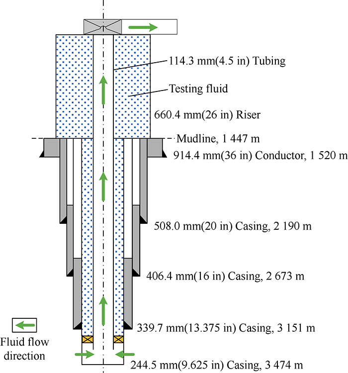
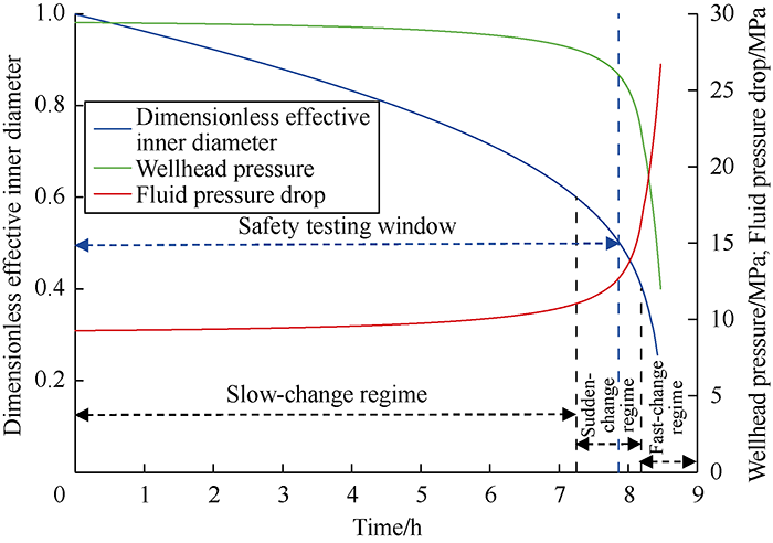
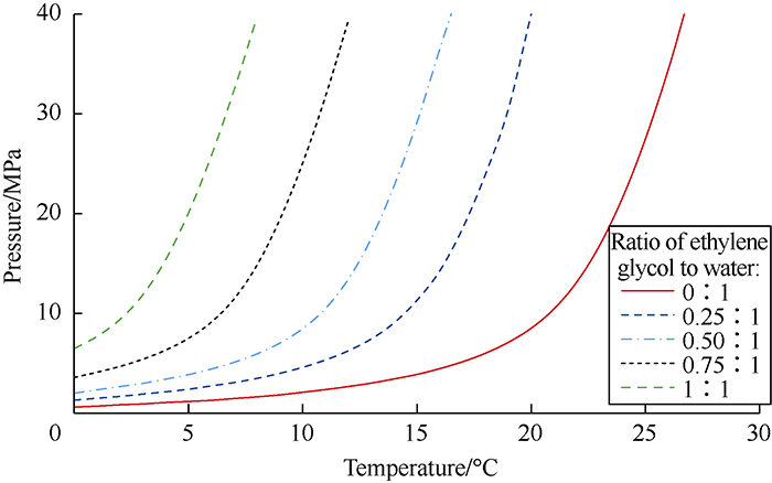
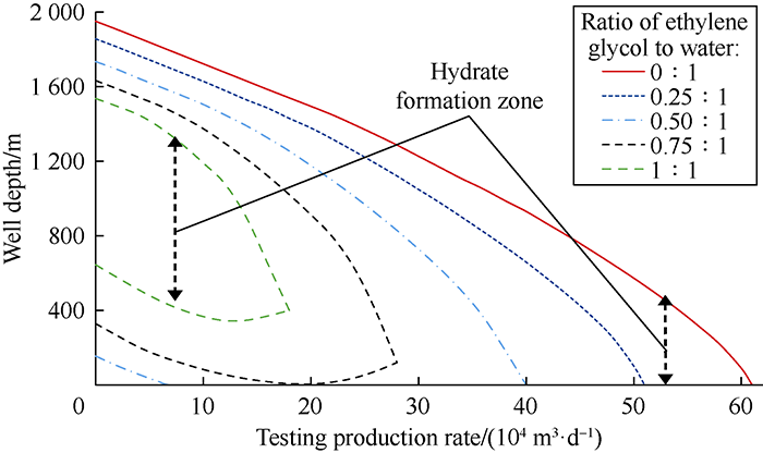
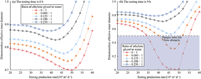

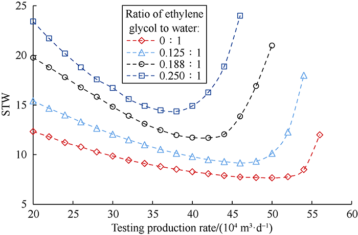
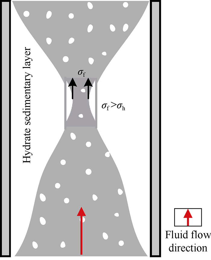
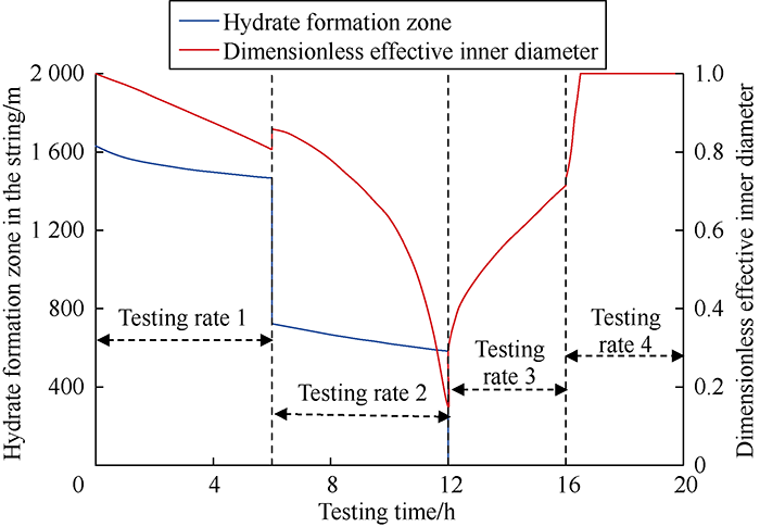
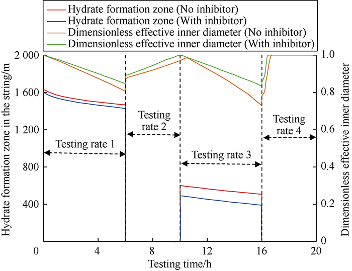

