

Introduction
High-permeability zones (HPZs), also known as "high-permeability layers", "thief layers", "ultra-high permeability layers", "ultra-HPZs" and "dominant flow channels", refer to thin reservoirs within an oil reservoir with significantly higher permeability than the adjacent reservoir and a significant contribution to fluid production [1-3]. The Cretaceous lithology in the Middle East is primarily carbonate rock, and HPZs are commonly found within reservoirs. HPZs have high initial production in depletion-development carbonate reservoirs and are the primary contributor to production capacity. However, during waterflooding, the injected water rapidly advances along the HPZs, leading to early water breakthrough and rapid watered-out of production wells, resulting in poor water-flooding effectiveness [4-6]. After carbonate reservoirs in the Middle East transitioned from depletion production to full-scale waterflooding, the presence of HPZs created major challenges. These included prominent contradiction, uneven reserve utilization, rapid increases in water cut, and ultimately low recovery efficiency [7-10]. The geological causes of HPZs in carbonate rocks in the Middle East are complex [11-16]. Their permeability depends on both their absolute permeability and the permeability ratio of the adjacent reservoir. There is no universe identification standard [17-20]. Clarifying the flow mechanism and waterflooding characteristics of HPZs with different genesis or distribution patterns, formulating reasonable development technical strategies, and deploying targeted well patterns are fundamental approaches to improve waterflooding efficiency and achieve balanced reservoir development in carbonate reservoirs.
Based on the waterflooding development practices of multiple carbonate reservoirs in the Middle East, this paper clarified the geological characteristics, water flooding characteristics, and watered-out patterns of different types of HPZs. The study proposed practical technical strategies and development models aimed at maximizing the waterflooding swept volume, controlling water breakthrough, and mitigating the rise in water cut in oil producers. The findings provide valuable support for the efficient waterflooding development of carbonate reservoirs in the Middle East.
1. Geological characteristics of HPZs
1.1. Causes and identification of HPZs
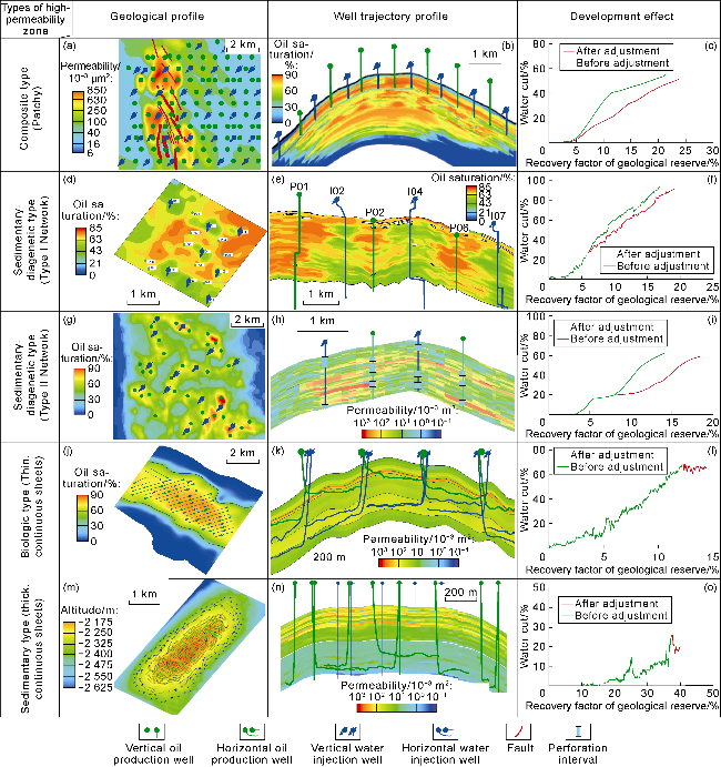
Based on the development experience of over 40 carbonate reservoirs in the Middle East, HPZs are characterized by permeability greater than 100×10-3 μm2, permeability contrast with the adjacent reservoir greater than 10 and liquid production contribution rate over 50%. Based on analysis over 70 cored wells (approximately 5 000 m of core, 9 500 physical property samples, 3 500 cast thin sections, and 1 800 mercury injection tests), 2 300 well logs, and over 2 000 production logging (PLT) data, carbonate HPZs in the Middle East are classified into types of sedimentation-dominated, sedimentation-diagenesis coupling, biogenic, and composite (referred to as sedimentary, sedimentary-diagenetic, biogenic, and composite) based on the main controlling factors of pore genesis and physical properties (Fig. 1).
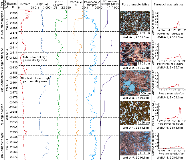
Fig. 1. Characteristics of different types of HPZs. |
Sedimentary HPZs are controlled by high-energy sedimentation. The sedimentary facies are mainly grain shoal. The lithology is mainly oolitic limestone and calcarenite. The thickness ranges from 3 m to 10 m. These features are significantly different from the adjacent reservoir. It is most typical in the Lower Cretaceous Thamama Formation in the Abu Dhabi area on the southern coast of the Persian Gulf [21]. Its pore type is mainly intergranular pore, with high texture maturity, a concentrated throat radius, a high proportion of large throat development, and weak microscopic heterogeneity. The well logging curve is characterized by low gamma, middle-high resistivity, and low density (Fig. 1a).
Sedimentary-diagenetic HPZs are the outcome of the coupling of high-energy sedimentation and constructive diagenesis [22]. They are mainly developed in bioclastic banks and tidal channels. They are composed of bioclastic granular limestone, with obvious scour structures, cross-bedding or karst features. The thickness of a single layer ranges from 1 m to 5 m, which is significantly different from the adjacent reservoir, such as wackestone or packstone. This type of HPZs is most typical in the Mishrif Formation of the Middle Cretaceous in southeastern Iraq. The pore types of HPZs are primary intergranular pores and secondary dissolution pores, with low texture maturity. The throat radius of the HPZs in tidal channels is 2.5-7.5 μm, and the throat radius of the HPZs in bioclastic banks is mostly over 5 μm, with a maximum of 25 μm. The well logging curves are characterized by low gamma, high resistivity, and low density readings, typically exhibiting bell-shaped, box-shaped, or funnel-shaped morphologies (Fig. 1b).
Biogenic HPZs are closely related to bioturbation. Bioturbation alters the texture and composition of the rock. The bio-burrows have extremely high permeability, resulting in a significant permeability difference from the adjacent reservoir [23-25]. Multiple phases of biological activity have resulted in interconnected burrows, forming HPZs. These zones are generally less than 2 m thick and have distinct boundaries from the adjacent reservoir, which is characterized by sparry granular calcarenite. They exhibit distinct contrasting characteristics (Fig. 1c). These zones are most commonly observed in the Upper Cretaceous Khasib Formation in southeastern Iraq. The well log curves are characterized by middle-low gamma, middle-high resistivity, and middle-high density [26].
Composite HPZs are the result of the combined influence of sedimentation, diagenesis, and tectonic processes. The high-energy sedimentary environment provided a favorable material foundation. The penecontemporaneous dissolution effectively improved physical properties. Burial faults connected deep diagenetic fluids. Burial dissolution further increased reservoir permeability. Pore types primarily consist of intergranular pores, cavities, and coelom pores. These HPZs were deposited mainly in a mound-bank environment. Their lithology is primarily bioclastic grainstone or micritic bioclastic limestone, with a thickness of 2-6 m. The adjacent reservoir is primarily packstone or wackestone. The average permeability of these composite HPZs is around 2 000 × 10-3 μm2. The throat radius is typically greater than 25 μm. The logging curve is characterized by middle-low gamma, high resistivity, and low density, with a funnel-shaped morphology (Fig. 1d).
1.2. Distribution pattern of HPZs
Based on the characterization of the distribution of HPZs in more than 40 Cretaceous carbonate reservoirs in the Middle East, three types of HPZs distribution patterns are summarized, which are patchy, network and continuous (Fig. 2), according to the scale, connectivity and planar morphology of the HPZs. The continuous zones can be further divided into thin layers and thicker layers based on their thickness.
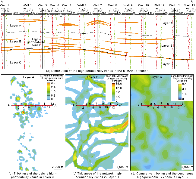
Fig. 2. Spatial distribution of HPZs of different styles in the Mishrif Formation of A Oilfield, Iraq (GR—natural gamma ray; ρ—density). |
HPZs of different origins typically exhibit distinct distribution patterns. Patchy patterns are primarily found in composite HPZs, network patterns in sedimentary-diagenetic HPZs, and continuous patterns in sedimentary and biogenic HPZs. A small number of sedimentary-diagenetic HPZs also exhibit continuous patterns. (1) Patchy distribution. HPZs are small in scale and poorly connected. They appear isolated in planar distribution within relatively low-permeability adjacent reservoirs (Fig. 2b), resulting in a low single-well drilling encounter rate. On the horizontal axis, local overlapping of HPZs can form thick, large-scale aggregates, reaching a thickness over 10 m. The distribution of the composite HPZs in the A layer of the Mishrif Formation in the A oilfield in Iraq is patchy. The HPZs are distributed along the mounds and shoals [27]. (2) Network distribution pattern. On the plane, the HPZs are strips, with a thickness of decimeters to meters. The distribution along the belt direction is stable, with good connectivity between wells. However, it quickly pinches out in the direction perpendicular to the belt. The adjacent reservoirs have medium and low permeability characteristics. Multiple HPZs are in contact and overlap with each other to form a network. The overlapping thickness is up to more than 10 m. This type of HPZ develops in tidal channels, which are highly directional and exhibit frequent migration and evolution, as well as weak regularity in their plane distribution. The sedimentary-diagenetic HPZs in the B layer of the Mishrif Formation in the A Oilfield in Iraq are distributed in typical network pattern. (3) Continuous sheet-like distribution pattern. The HPZs are distributed in a continuous, sheet-like manner within the oil field, exhibiting a stable planar distribution. The single-well drilling encounter rate is high. The adjacent reservoirs have mostly medium to low permeability. Continuous HPZs are common. Their thickness varies greatly. The thickness of a single HPZ is mostly 0.5-5.0 m. The thickness of multiple HPZs can reach 10 m or more when superimposed. The cumulative thickness of the sedimentary-diagenetic HPZs at the top of the C layer of the Mishrif Formation in the A oilfield in Iraq is up to 5.4 m (Fig. 2d). The thickness of the sedimentary-type HPZs in the Thamama Formation in the D Oilfield in the UAE is close to 5 m, and the thickness of the biological-type HPZs in the Khasib Formation in the C oilfield in Iraq is about 1 m.
2. Water flooding characteristics and watered-out patterns of HPZs
2.1. Microscopic water flooding characteristics and flow mechanism in HPZs
The Cretaceous HPZs in the Middle East have different causes, and their microscopic water flooding characteristics and flow mechanisms differ significantly. (1) Sedimentary type: The pore throat radius distribution is primarily unimodal (Fig. 2a), exhibiting a hook-shaped permeability curve (Fig. 3). Water cut rises slowly in the early stages but rapidly in the later stages. (2) Sedimentary-diagenetic type: The pore-throat radius distribution is right-skewed. Initial mercury injection pressure is generally extremely low. After water flooding, the fluid advances in the direction with the minimum flow resistance. Due to the uneven distribution of large pores and coarse throats, the reservoirs exhibit strong heterogeneity. The interconnected large pores enable water to rapidly break through these pathways, which results in low sweep efficiency. It shows an "X-shaped" relative permeability curve, and low oil displacement efficiency. (3) Composite type: The pore throat radius distribution is predominantly right-skewed. The initial mercury injection pressure is generally higher than that of the sedimentary-diagenetic type. The difference in number between the largest pore throat radius and the remaining pore throat radii is significantly smaller than that of the sedimentary-diagenetic type. The reservoir is relatively homogeneous. After water flooding, the fluid advances evenly along the flow channels in all directions, resulting in high sweep efficiency and high oil displacement efficiency. At the same water saturation, the water-phase relative permeability of the composite type is lower than that of the sedimentary-diagenetic type (Fig. 3). (4) Biogenic type: Due to the mechanical transformation of the hard bottom by organisms, the formation structure is loose and well-connected flow channels are formed. However, due to the poor physical properties of the adjacent reservoir, the two-phase flow zone is narrow. As a result, it shows an "X-shaped" relative permeability curve (Fig. 3), and low oil displacement efficiency.
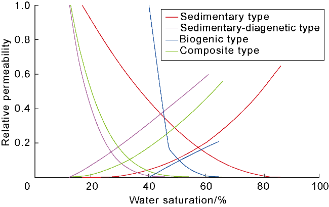
Fig. 3. Typical relative permeability curve of HPZs in carbonate reservoirs in the Middle East. |
In general, the sedimentary type involves destructive processes such as cementation and compaction. These processes are usually found in oolitic limestone and calcarenite. Due to the good sorting and rounding of oolitic grains and arene, intergranular pores are well developed. The pore structure is monomodal, with a wide two-phase flow zone. It has high oil displacement efficiency. Sedimentary-diagenetic, biogenic, and composite types often exhibit multimodal pore structures due to the selective dissolution, bioturbation, and tectonic effects that result in the formation of large pores, caves, and fractures in local areas. Due to the order of magnitude difference between large and small pores, water easily breaks through along the large pores, resulting in a narrow two-phase flow zone and generally low oil displacement efficiency.
2.2. Watered-out patterns in HPZs
HPZs have a significant impact on water injection energy replenishment, oil production stabilization, and water cut control in thick carbonate reservoirs. Generally, for commingled water injection, injected water preferentially flows along HPZs with better physical properties, resulting in a large amount of ineffective water circulation and ineffective sweeping of low-permeability reservoirs. This leads to large differences in sweep efficiency between layers, premature water breakthrough in oil producers, and increased surface corrosion [7,28]. The different distribution patterns of HPZs lead to significant differences in injection-production connectivity, resulting in distinct production performance.
Composite HPZs typically distribute as patches at the top of isolated mound-bank body. Their distribution area is limited (Fig. 4a). When injection and production wells are parallel to the HPZs, oil producers experience an immediate improvement in oil production. However, water cut increases rapidly after breakthrough. When the injection-production well spacing is greater than the HPZ's size, water flooding shows weak impact. The injection and production are poorly correlated. Oil producer is poorly affected or not affected by the water flooding. When the injection-production well spacing is less than the HPZ's area, the injection and production are well correlated. Oil producers experience improvements in oil production, and the injected water rapidly advances, resulting in gradual watered-out phenomena (Fig. 4b). Horizontally, the injected water follows an uneven flooding path along the irregular, patchy HPZs, resulting in various water breakthrough times for wells in different directions. Wells with high water cut are generally isolated within the HPZs. Vertically, the HPZs exhibit strong fluid production and water absorption capacities, resulting in low vertical production. For example, in the A layer of the Mishrif Formation in the A oilfield in Iraq, the injection-production well spacing is smaller than the size of the patchy HPZ. 80% of the high-rate wells are located in the HPZ. Because water injection wells or converted injection wells are also distributed in the HPZ, the injected water quickly advances along the HPZ (Fig. 4b), causing the production of high-rate oil producers to drop rapidly while the water production increases rapidly (Fig. 4c). The water breakthrough time is usually 1-2 years, which is earlier than that of oil producers that are not within the HPZs. The water cut of 40% of the wells with water-breakthrough increases rapidly in a "convex" shape (Fig. 4d).
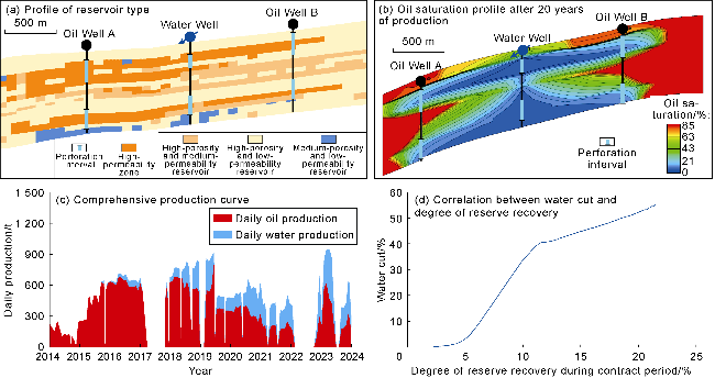
Fig. 4. Development characteristics of composite HPZs (typical well group in the A layer of the Mishrif Formation reservoir in A Oilfield, Iraq). |
The sedimentary-diagenetic HPZs developed in bioclastic shoals are distributed in continuous sheets, following the same watered-out pattern as sedimentary HPZs. Those developed within tidal channels are distributed as a network. Based on the scale and stacked pattern of these network HPZs, they can be subdivided into two flooding patterns (Type I and Type II).
Type I network: HPZs are primarily distributed in the mainstream of tidal channels. No HPZs develop in its tributaries. Injection-production well groups are in the mainstream tidal channel (Fig. 5a). For example, in the Mishrif Formation of the B Oilfield in Iraq, large tidal channels are developed in the MB1-2 layer, with localized development. Injected water rapidly advances along the HPZs at the bottom of the tidal channel (Fig. 5b). After water breakthroughs in the production wells in the mainstream tidal channel, oil production decreases and water cut rises rapidly (Fig. 5c). The water cut in the oil producers shows a rapidly rising "convex" pattern. At the end of the contract period, the degree of reserve recovery was only 15%, but the water cut was as high as 80% (Fig. 5d).
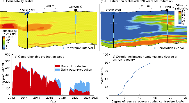
Fig. 5. Development characteristics of sedimentary-diagenetic (Type I network) HPZs (typical well group in the MB1-2 layer of the Mishrif Formation in the B Oilfield, Iraq). |
Type II network: multiple tidal channels stack laterally or vertically. Individual tidal channel is small. The overlapping channels form a complex. Injection and production wells are located within the channel complex (Fig. 6a). Intervals where injection and production are effective exhibit high oil and water production rates. Unaffected intervals have low oil production but no water production (Fig. 6b). For example, in the B layer of the Mishrif Formation in the Oilfield A, Iraq, the tidal channels are 1-2 km wide and network of stacked channels.
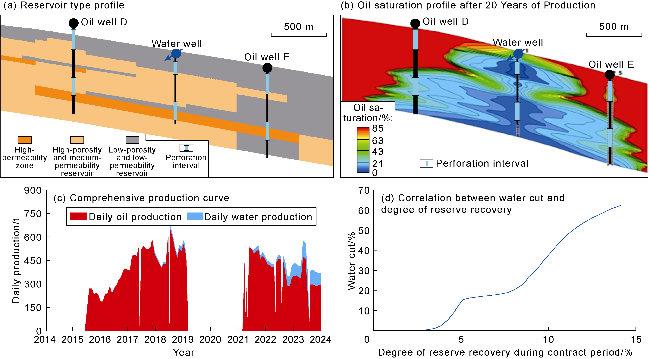
Fig. 6. Development characteristics of sedimentary-diagenetic (Type II network) HPZs (typical well group in the B layer of the Mishrif Formation in Oilfield A, Iraq). |
The perforations in the lower portion of the injection and production wells encounter HPZs. Injected water channeling along these lower HPZs causes watered-out phenomena in the corresponding oil producers. Injection wells drilled above the tidal channels do not encounter HPZs, resulting in uniform propagation of injected water and a slow response in the corresponding oil producers (Fig. 6b). Wells in the tidal channel complex typically produce more than 288 t/d. When water breaks through in the production wells, oil production drops significantly, while water production gradually increases (Fig. 6c). When the degree of reserve recovery is less than 5%, water breakthrough in the oil producer forms an early dominant water flow channel. The water cut rises rapidly to 20%. However, because HPZs are developed in all tidal channels and their thickness accounts for a relatively high proportion of the tidal channels, the swept volume of injected water gradually expands and the water cut remains stable when the degree of reserve recovery is 5% to 10%. As the degree of reserve recovery increases further, the injected water quickly channels along the HPZs, forming new dominant water flow channels, and the water cut rapidly increases to 60% (Fig. 6d).
Biogenic HPZs typically occur as thin, continuous sheets, with relatively small thickness, large horizontal scale, and good connectivity. Injection and production wells are all within the plane of the HPZs. Injected water rapidly progresses along the HPZs, resulting in early water breakthrough for production wells (less than one year). Horizontal water injectors are often used for development. Production wells below the HPZs have a long water-free production period and a relatively slow rise in water cut, yielding the best development results. Wells across the HPZs have the second-best development results. Wells above the HPZs have the worst performance. When thin HPZs are developed within a reservoir, the injection wells are adjacent to the lower medium-permeability reservoir layer, and the production wells are located below the upper HPZs (Fig. 7a). Due to the low pressure in the upper HPZs, the injected water, once entering the reservoir, primarily migrates vertically near the wellbore to the upper HPZs, and then flows laterally to the production wells, causing watered-out phenomena. Meanwhile, some injected water flows under gravity along the medium-permeability reservoir layer (Fig. 7b). Among the vertical sublayers, only the high-permeability thin layer has significant watered-out degree, followed by watered-out signs near the injection well, and the other sublayers have low watered-out degree. The injected water presents a similar "I"-shaped watered-out pattern. The overall water flooding sweep efficiency is poor [29]. For example, the upper part of KH2 Formation in the C Oilfield in Iraq has a thin, continuous HPZ with an average thickness of 0.8 m and an average permeability of 248× 10-3 μm2. Some core permeabilities exceed 1 000×10-3 μm2. Waterflooding was applied in a horizontal well pattern, where the horizontal injector was positioned directly beneath a horizontal producer. The horizontal wells were 800 m long with well spacing of 100 m and row spacing of 300 m. The lateral section of the production wells was mostly in HPZs. The reservoir had a large ratio of vertical to horizontal permeability. The average vertical distance between the oil and water wells was just 7.2 m. The above factors resulted in an "I”-shaped watered-out pattern and a high watered-out degree in the thin HPZs (Fig. 7b). After waterflooding, the corresponding production wells experienced rapid water breakthrough, with individual well production quickly dropping to below 144 t/d (Fig. 7c). The water cut rapidly rose to over 50%. When the degree of reserve recovery reached 25%, the water cut reached 80%, resulting in poor waterflooding efficiency (Fig. 7d).
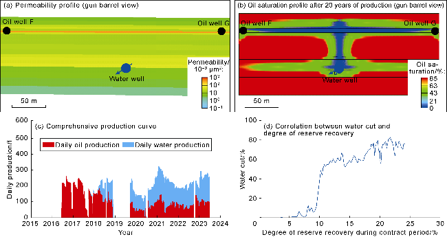
Fig. 7. Development characteristics of biological HPZs (typical well group in the KH2 Formation of the C Oilfield in Iraq). |
Sedimentary HPZs typically occur as thick, continuous sheets. They are thick, and mostly develop vertically in the upper reservoir. They exhibit an anti-rhythmic pattern in general. Development is implemented in phases using off-edge water injection and a wide well spacing. Both injection and production wells are perforated in the HPZs and the general reservoir. Packers are installed between the two perforation intervals of production wells to prevent water from flooding the lower reservoir (Fig. 8a). During development, injected water from both perforation intervals in the injection wells tends to migrate along the HPZs, causing the upper perforation interval to be activated first and flooded. The lower perforation interval does not produce liquid (Fig. 8b). For example, the Thamama Formation in the D Oilfield in the United Arab Emirates and the C formation of the Mishrif Formation in the A Oilfield in Iraq have anti-rhythmic vertical properties. Thick HPZs are located in the upper reservoir. Since water injection began, the upper HPZ has been flooded. After water occurred in the upper perforations of the well, the upper perforations were plugged and the packers opened. It allowed the upper water to displace the oil and gas below under gravity, forming an "inverted water cone" (Fig. 8b). After the water breakthrough in the well, the water cut rose rapidly, leading to a significant decline in production (Fig. 8c). Through phased production of the upper and lower strata, the degree of reserve recovery reached 25% during the contract period. The water cut was kept below 25% (Fig. 8d).
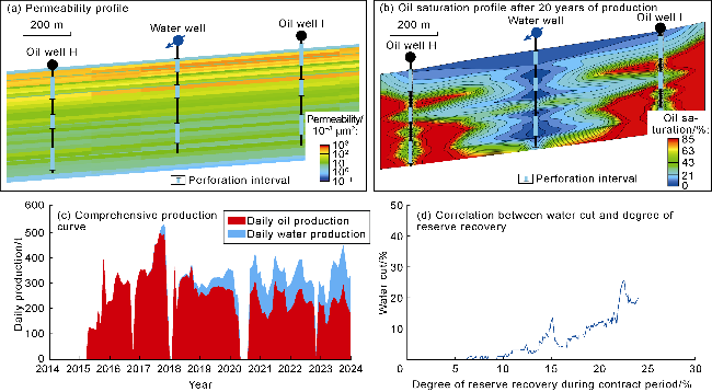
Fig. 8. Development characteristics of sedimentary HPZs (typical well group in the Thamama Formation of the D Oilfield in the UAE). |
The distribution of different types of HPZs has great impacts on water injection flooding performance, vertical utilization conditions, and development effectiveness. Composite HPZs exhibit a patchy distribution, severe heterogeneity, irregular horizontal flow pathways, and low vertical utilization degree. These zones require precise control of injection-production well spacing, and optimization of well patterns and injection-production parameters. For sedimentary-diagenetic HPZs, the base of Type I tidal channels constitutes the primary dominant flow pathway. They exhibit significant variations in vertical utilization. Water injection in separate layers can enhance production in low-utilization zones. The base of Type II multi-stage tidal channels exhibits superimposed flooding. It has more complex flooding pathways than Type I. Precise optimization of perforation positions and injection-production well patterns are much needed. Biological HPZs have thin, continuous layers, with extremely rapid progression of injected water as I-shaped. For these zones, the development mode of horizontal well water injection is well suitable. Development results are optimal when the horizontal well trajectory is located below the HPZ. Adjusting injection intensity and flow direction can also improve waterflooding effectiveness. Sedimentary HPZs are thick, continuous sheets with an anti-rhythmic pattern in the upper reservoir. The upper perforated interval of the well is flooded first, while the lower interval remains dry. Subsequent plugging of the upper interval and the use of gravity to form an "inverted water cone" for phased production are then implemented. Flexible matching of various well patterns and phased development adjustments can help improve waterflooding effectiveness. In conclusion, the waterflooding of different types of HPZs vary significantly. It is necessary to customize specific technical strategies, and select the most appropriate development models so that the waterflooding efficiency can be continuously improved.
3. Water flooding development technical strategies and development models
3.1. Technical strategies for water flooding development
In view of the HPZs commonly developed in carbonate reservoirs in the Middle East, corresponding development technology policies are proposed based on their distribution patterns, flow mechanisms, water flooding characteristics and watered-out patterns to guide the efficient and balanced water injection development of carbonate reservoirs.
(1) Development strata are divided based on the distribution of HPZs. When a reservoir contains multiple HPZs of different origins and with different distribution patterns, they should be reasonably divided into two or more development strata based on the HPZs, even if there are no stable barriers. If a reservoir contains multiple HPZs of the same origin and with a uniform distribution pattern, they can be considered as one development strata, even if there are stable barriers.
(2) Designing well patterns and layouts with flexibility and rationality helps improve the injection capacity of water injection wells. A flexible and diverse well pattern can increase the contact area between production wells and HPZs. A rational well pattern and layout can adjust flow line fields, slow the rise of water cut, and improve the injection capacity of water injection wells. For water injection wells located in adjacent reservoirs with poor physical properties, high-pressure water injection and acid fracturing can be used to improve injection capacity.
(3) Effectively utilizing and avoiding HPZs can improve the production and water absorption capacity of the surrounding reservoir. Vertical flow field is controlled by adjusting the completion strategy of injection and production wells. Perforating HPZs or relatively favorable reservoirs in production wells increases the production of individual wells. Avoiding perforation of HPZs in injection wells and adjusting the water injection volume for different layers effectively prevent water channeling along HPZs. Avoiding general perforation of HPZs and surrounding reservoirs reduces the weakening effect of HPZs on the development characteristics of surrounding reservoirs.
(4) Reducing the production differential pressure in HPZs and maintaining stable water injection into the surrounding reservoir is necessary. Rationally control the production differential pressure of oil producers to extend the waterless or low-water production period. Carry out slow and gentle water injection and rationally control the injection-production ratio to fully utilize the imbibition effect to effectively displace crude oil from the surrounding reservoir. If the water injection is too fast, the injected water will cause a rapid increase in bottomhole pressure and move quickly along the path of least flow resistance. Once the injected water enters the HPZs, it will cause water channeling, thereby reducing the swept volume.
(5) Real-time conversion of the role of HPZs in waterflooding development shall be guaranteed. Based on the specific characteristics of HPZs and development challenges, this study optimizes development methods by incorporating production performance, water cut trends, and remaining oil distribution across different development stages. This approach enables dynamic, rolling adjustments in waterflooding strategies to enhance reservoir recovery. In the early stages of waterflooding development, HPZs are still the main high-yield layers. It is advisable to reduce the production pressure difference to maximize the maintenance of the water-free or low-water oil production period. As the water cut increases, HPZs gradually become the dominant channels for water channeling. By optimizing the injection-production relationship, the increase rate of water cut can be slowed down. When high water cut or violent flooding occurs, the HPZs should be plugged or wells should be shut in to prevent the flooded layers from spreading to other sections.
3.2. Water flooding development mode
Based on the distribution characteristics of HPZs and the different flooding patterns during development, water flooding development modes can be divided into five categories: stepwise-infilled areal vertical well pattern water flooding mode, regular row vertical well pattern water flooding mode, irregular differentiated vertical well pattern water flooding mode, row horizontal well bottom injection and top production model, and progressive water flooding mode with edge water injection via vertical well and oil production via horizontal well.
A stepwise-infilled areal vertical well pattern waterflooding mode: Composite HPZs are patchy, with a small horizontal extension, multimodal pore throats, a narrow two-phase flow range, and low oil displacement efficiency. Therefore, an inverted nine-point vertical well pattern is employed. Horizontally, a basic areal vertical well pattern with wide well spacing is initially deployed to comprehensively control the reserves of the highly heterogeneous HPZs (Fig. 9a). Later, appropriate infilling of the pattern is implemented to establish a planar displacement pattern with a weak starting point and a strong surface, improving planar displacement efficiency. Vertically, a differentiated perforation strategy is employed, with oil producers perforating the mound-shoal reservoir and its HPZs (Fig. 9b). The perforations of water injection wells are primarily deployed in the lagoonal reservoir, avoiding HPZs and faults. High-pressure water injection and acid fracturing augmentation techniques are used to improve water injection capacity, gradually displacing oil and gas from the lagoonal reservoirs. The vertical waterflooding process is precisely controlled to coordinate planar and vertical sweep efficiency, achieving a balanced injection-production profile in the composite HPZs.
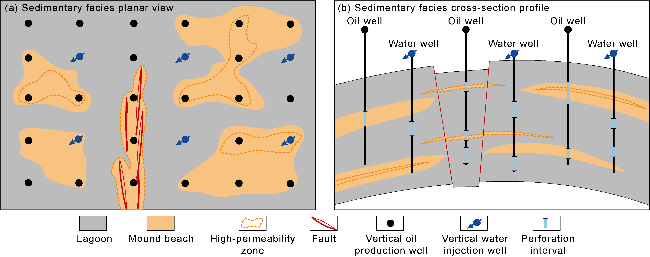
Fig. 9. Stepwise-infilled areal vertical well pattern waterflooding mode for composite HPZs. |
Regular row vertical well pattern waterflooding mode: Type I network HPZs of Sedimentary-diagenetic HPZs develop in the main tidal channel. Regarding their large scale and thickness, and network-like distribution along the tidal channel, a regular row vertical well pattern with large well spacing is utilized. Horizontally, most production wells are deployed in the main tidal channel, with a small number of wells in the lagoon. Injection wells are primarily deployed in the lagoon (Fig. 10a). The pore throats of these HPZs are predominantly multimodal. Water easily breaks through along these large pore throats. Two-phase flow space is narrow and oil displacement efficiency is low. To prevent water channeling from injection wells in the tidal channel or HPZs, the vertical displacement by stratified water injection is strengthened to improve the interlayer differences caused by the network HPZs. Injection wells are primarily perforated in lagoons (Fig. 10b). Due to gravity, the injected water in the lagoon reaches the HPZ below, causing the production wells to be flooded. For production wells with severe flooding, the HPZ is plugged. For production wells in the lagoon, vertical well fracturing and well pattern thickening can be used to develop low-permeability, hard-to-produce reservoirs effectively.
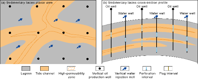
Fig. 10. Water flooding mode of regular row vertical well pattern in sedimentary-diagenetic HPZ. |
Irregular differentiated vertical well pattern water flooding mode: Type II network HPZs of sedimentary- diagenetic HPZs are developed in tidal channel tributaries. With a focus on the small-scale and network-like distribution characteristics of HPZs, an irregular differentiated well pattern water flooding mode is deployed according to the morphology of HPZs, injection-production connectivity, development scale, and physical property differences. Horizontally, production wells are primarily in a tidal channel network of HPZs, while injection wells are in lagoons. Well spacing is determined flexibly, and an overall irregular injection-production relationship similar to the inverted five-point method is adopted (Fig. 11a). High-quality reserves in the tidal channels are initially developed, followed by the targeting of low-quality lagoon reserves for production to replace them. This approach optimizes the injection-production relationship of planar displacement and. It also effectively addresses the complex sweeping of injected water caused by the superposition of multiple tidal channels. Vertically, the perforated intervals of production wells are deployed in a tidal channel network of HPZs, while the perforated intervals of injection wells are primarily deployed in lagoons (Fig. 11b). This addresses the significant differences in the producing conditions of various layers caused by the superposition of tidal channels from different periods and increases the overall swept volume by the injected water.
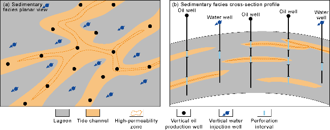
Fig. 11. Water flooding mode of irregular differentiated vertical well pattern in sedimentary-diagenetic HPZs |
Row horizontal well bottom injection and top production mode: The biologic HPZs are thin and continuous. Pressure can propagate far horizontally. For these reasons, a gentle injection-production pattern in horizontal wells is preferred, resulting in a horizontal well pattern with bottom-injection and top-production (Fig. 12a). The HPZs exhibit a monomodal pore throat pattern. Water can easily break through along these large pore throats. This results in a narrow two-phase flow zone and low oil recovery efficiency. Production and injection wells are sidetracked to avoid the HPZs. The laterals of production wells are positioned below HPZs (Fig. 12b). Variable-density screens and automatic inflow control devices (AICDs) are used for completions to control water and delay water breakthrough in horizontal wells thereby improving reservoir utilization. Precisely tune the vertical horizontal well trajectories to optimize the vertical waterflood sweep volume, and employ the advanced horizontal well completion technologies to flexibly adjust injection intensity and flow direction, which further enhances waterflooding effectiveness.
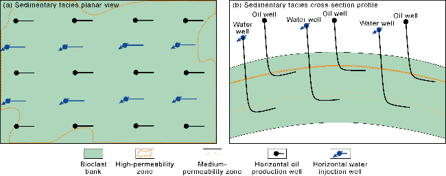
Fig. 12. Row horizontal well with bottom injection and top production in biological HPZs |
Progressive water flooding mode with edge water injection via vertical well and oil production via horizontal well: When the effective reservoir thickness of oil reservoirs with sedimentary HPZ satisfies the requirements of subdivided strata, and thick continuous HPZs are developed in the upper part of the reservoir, stratified development is implemented. A water injection development mode with edge water injection in large cutting distance as the main approach and gradual inward rolling strategy is established. The development method and well pattern are adjusted in phases. Horizontally, vertical water injection wells are in the edge water of the reservoir, and horizontal oil production wells are in the higher interval of the reservoir. Water injection points are added locally as point-like vertical wells (Fig. 13a) to balance the adverse effects of water injection in the HPZs. This method significantly improves the horizontal displacement efficiency. Vertically, dual-pipe completion and other technologies are used to achieve stratified development, alleviating the contradiction between vertical layers. It prioritizes the development of high-quality reserves in medium- to high-permeability zones, and then gradually sidetracks to the bottom. Gravity differentiation is conducive to improve the vertical displacement effect. Flexible combinations form a mixed-area injection and production well pattern with various well types, including vertical and horizontal wells, to achieve the comprehensive utilization of three driving relationships: horizontal drive, vertical drive, and oil-water differential gravity drive. It continuously expands the swept area of water flooding (Fig. 13b).
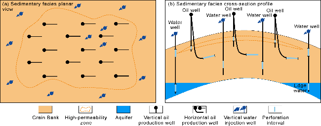
Fig. 13. Progressive water flooding model with vertical well for edge water injection and horizontal well for oil production in sedimentary HPZs. |
4. Application
The above five water flooding modes have been implemented for different types of HPZs in the Middle East, with promising application results.
A layer of the Mishrif Formation in the A oilfield in Iraq has developed a complex HPZ, which is distributed as a patch. Before the adjustment, a commingled injection- production approach was used for the A layer and its underlying high-permeability reservoir which is composed of tidal channels and bioclastic shoals. The well perforated interval had a thickness of up to 90 m. This extensive production model led to a severe vertical imbalance in production and water channeling in the oil producers. After changing to a stepwise-infilled areal vertical well pattern water flooding, the commingled injection- production vertical wells were precisely classified in the early stages of development. Then, an areal inverted nine- point vertical well pattern with a spacing of 900 m was established in the A layer (Fig. 14a, 14b). High-pressure water injection and acid fracturing significantly improved the injection capacity of the water injectors. The optimized well pattern and water injection strategy successfully controlled the high-quality reserves in the patchy HPZs, improving development yields. The average daily oil production per well reached 216 t, and the daily water injection per well was close to 865 t. The interim recovery factor of the geological reserve was expected to increase by 3% (Fig. 14c). In the middle and late stages, once the water cut of the oil producers increased, the water drive swept volume was further expanded by switching producer to injector and converting to a five-point enhanced water injection pattern with smaller well spacing.
Fig. 14. Application results of different types of water flooding modes in different HPZs. |
MB1-2 layer of the Mishrif Formation in the B oilfield in Iraq has developed sedimentary-diagenetic HPZs, distributed as a Type I network. Before adjustment, a commingled injection-production pattern with vertical well spacing of 600 m was used. As a result, utilization rate on the vertical direction was only approximately 35%, severely restricting balanced reservoir development. This was changed to a waterflooding pattern with a regular vertical well pattern. It was an innovative, differentiated adjustment strategy: in the reservoir's highlands, the vertical well pattern was adjusted from an inverted nine-point pattern to a line drive well pattern. In the flanks, an inverted nine-point pattern was deployed with highly deviated wells. Furthermore, differentiated perforating and acid fracturing, along with washing, were applied to enhance injection-production connectivity. The injection-production relationship was continuously optimized through stratified oil recovery and phased waterflooding (Fig. 14d, 14e). Significant results were achieved in the pilot area after the adjustment, with a 9.2% increment in waterflood swept volume and a 3% increment in estimated interim recovery factor of geological reserves (Fig. 14f).
B layer of the Mishrif Formation in the A oilfield in Iraq develops sedimentary-diagenetic HPZs, distributed as a Type II network. There are also sedimentary- diagenetic HPZs in the underlying C layer, which are thin and continuous. Before adjustment, an inverted nine-point vertical well pattern was used to inject and produce the type II network HPZs in B layer and the continuous HPZs in its underlying C layer together. However, the flow characteristics of different tidal channels were not considered. A large number of injection wells were perforated at the bottom of the tidal channels. This resulted in severe channeling of injected water along the type II network HPZs, with large amounts of water flowing into the underlying C layer. Consequently, water broke through in the underlying oil producers and there were significant inter-layer production differences. Therefore, an irregular differentiated vertical well pattern was adopted for water flooding. This pattern was deployed to utilize the high-quality reserves in the tidal channels. The completion for the injection wells was optimized based on the development patterns of tidal channels during different periods. Only the top two tidal channels were perforated, while the bottom channel was not perforated (Fig. 14g, 14h). This effectively slowed down the rapid advance of injected water. After the adjustment, the production from the producing vertical wells was between 216 t/d and 288 t/d. The recovery factor of the geological reserve was expected to increase by 4% (Fig. 14i).
The KH2 reservoir in the C Oilfield in Iraq develops biogenic HPZs, distributed as thin, continuous sheets. Prior to adjustments, numerous horizontal wells were located above the HPZs, causing rapid water flooding of the wells. The system was then adjusted to a row horizontal well bottom injection and top production pattern. Sidetracking was used to adjust the horizontal well trajectories below the HPZs. Water plugging and profile controlling measures were implemented to plug the water-producing sections of the HPZs (Fig. 14j, 14k). Precise water control measures of "increasing liquid reducing injection, controlling liquid reducing injection, and stabilizing liquid reducing injection" were implemented to lower the increase of water cut in the reservoir. As a result, water cut dropped by 3%-5% and production increased, achieving water control and an oil production increment (Fig. 14l).
The Thamama reservoir in the D Oilfield in the United Arab Emirates (UAE) has developed sedimentary HPZs distributed as thick, continuous sheets. Before adjustments, commingled water injection by vertical well was adopted, resulting in low swept volumes of water. This was changed to a progressive waterflooding mode with vertical well for edge water injection and horizontal well for oil production. The reservoir was divided into two development zones, and dual-pipe completion was adopted. Waterflooding shifted from outer to inner margins, and then gradually transitioned to internal cutting and area-based waterflooding. Existing vertical wells were sidetracked into the lower, low-permeability zones, creating a row-like well pattern with vertical wells injecting water and horizontal wells producing oil (Fig. 14m, 14n). Meanwhile, the well spacing was reduced to 250-500 m. Slow development was maintained, with oil production rates controlled within 1% and injection-production ratios between 0.8 and 1.2. After the adjustments, the interim recovery factor of the geological reserves in the lower strata of the Thamama reservoir is increased by 5%, with an average daily oil production increase of 43-72 t per well (Fig. 14o).
5. Conclusions
HPZs of four genesis types are developed in carbonate reservoirs in the Middle East: sedimentary, sedimentary-diagenetic, biogenic, and composite. These zones have three distribution patterns: patchy, network, and continuous. The thickness, size and connectivity of HPZs with different distribution patterns vary greatly.
The microscopic heterogeneity of HPZs controls the two-phase flow relationship and oil displacement efficiency. As the heterogeneity increases, the two-phase flow range and the oil displacement efficiency decrease. Sedimentary HPZs have a unimodal pore throat structure, weak microscopic heterogeneity, a wide two-phase flow range, and high oil displacement efficiency. Sedimentary-diagenetic, biogenic, and composite HPZs have a multimodal pore throat structure, a narrow two-phase flow range, and generally low oil displacement efficiency. In most commingled waterflooding development, the injected water quickly channels along the HPZs, causing premature water breakthrough or watered out phenomena in the oil producer. The water flooding swept volume is small, and the large-scale reserves in the adjacent reservoir cannot be effectively affected. The water injection does not replenish the energy well, resulting in a low degree of reserve recovery and uneven reserve utilization for thick carbonate reservoirs.
Based on the geological and development characteristics of HPZs, five waterflooding development technical strategies are proposed. These strategies are based on dividing development strata based on the distribution of HPZs, flexibly and rationally designing well patterns, improving the injection capacity of water injection wells, effectively utilizing and avoiding HPZs, improving the production and water absorption capacity of surrounding reservoirs, reducing the production pressure differential of HPZs, maintaining moderate water injection in surrounding reservoirs, and continuously shifting the role of HPZs in waterflooding development. The five waterflooding modes are established: a stepwise-infilled areal vertical well pattern, a regular row vertical well pattern, an irregular differentiated vertical well pattern, row horizontal well with bottom injection and top production, and progressive development with edge water injection via vertical well and oil production via horizontal well. Based on the structural patterns of the HPZs, these five waterflooding modes were implemented in various reservoirs in the Middle East with promising development results.