

Introduction
Enhanced oil recovery (EOR) of old oilfields and effective development of new fields, especially unconventional oil, are important to keep long-term stable oil production in China [1]. It is a challenge to enhance the post-waterflooding oil recovery of low- and ultra-low-permeability reservoirs with oil reserves of nearly 10 billion tons [2]. To this end, it is necessary to conduct multi-disciplinary fundamental study and promote disruptive technologies on theory and methods of reservoir stimulation [3]. Considerable efforts have been devoted to understanding interactions between oil and chemical displacement agents, and between rock and these agents [4]. On the other hand, interaction between oil and rock is another key factor affecting EOR. Typically, sandstone surfaces are negatively charged, while the polar components of oil also carry some negative charges [5]. Cations in formation water interact with both rock surface and oil, forming cation-hydration bridges which make it difficult for oil displacement. Stripping oil from rock surface involves thermodynamic and kinetic mechanisms. The kinetic mechanism represented by the separation pressure in a three-phase zone plays a vital role. Fang et al. [6] carried out simulation on effects of brine films in oil-brine-rock system and found that separation pressure occurs between oil and rock when the brine film reaches 1.0 nm thick. Zhang et al. [7] proposed that nano-fluids can generate structural separation pressure, thereby enhancing oil recovery.
Superwettable phenomenon occurs on the super-hydrophilic surface at contact angle less than 5° and the super-hydrophobic surface at contact angle greater than 150°. Superwetting technology has been applied in anti-fouling, oil-water separation, lubrication and tertiary oil recovery [8-13]. If an oil displacement agent creates a superwettable interface between rock surface and oil film, the cation-hydration bridge will be destroyed and the oil film will be stripped from the rock completely.
Hydroxyl groups (—OH) in anionic compound are adsorbed on sandstone surface through hydrogen bonding, and their anionic groups can enhance negativity on the surface, which strongly change the wettability of the rock surface. Moderately polar groups (polyoxypropylene or polyoxyethylene) are inserted between the hydrophobic alkyl and the hydrophilic head of extended surfactants, providing excellent emulsification and high interfacial activity [14-15]. A compound system of hydroxyl anion and extended surfactant provides selective action on oil-rock and oil-water interfaces, forming multi-interface, synergistic alteration of wettability, which induces superwetting phenomenon on rock surface. This study proposes a novel super-wettable compound system composed of sodium 1-hydroxyacetate (1OH-1C) and an extended sulfate surfactant (S-C13PO13S). The interfacial properties and oil displacement effects of 1OH-1C, S-C13PO13S and their compound system have been evaluated through experiments, revealing the synergistic displacement mechanism based on superwetting. The findings are helpful to designing highly efficient oil displacement agents, and improving oil mobilization within micro-nano pores by altering the wettability of oil-rock and oil-water interfaces. The technology is applicable for difficult-to-develop reservoirs, such as low-permeability and shale oil reservoirs whose recovery is controlled by rock-oil interfacial interaction.
1. Materials and methods
1.1. Materials
The chemicals include extended surfactant sodium 2, 5, 9-trimethyl-decyl polyoxypropylene ether sulfate (S-C13PO13S) produced by Sasol Chemicals Ltd., with an active content not less than 90%, and sodium 2-hydroxyacetate (1OH-1C) produced in laboratory, with a purity not less than 90%. 1OH-1C was produced by making chloracetic acid react with sodium hydroxide under an alkaline condition by controlling pH value around 9 and constant temperature at 80 °C for 2 h, and then concentrating, filtrating and cooling to crystallization. The molecular structures of the two kinds of compounds are shown in Fig. 1. Other inorganic chemicals are of analytical grade.
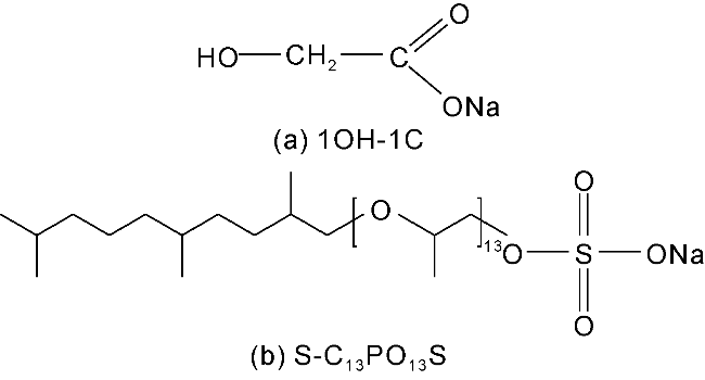
Fig. 1. Molecular structures of 1OH-1C and S-C13PO13S. |
The crude oil used in the experiments was collected from an oilfield in the Bohai Bay Basin, East China, where the formation temperature is 85 °C, the formation oil density is 0.813 g/cm3, and the surface oil density is 0.877 g/cm3. The oil was diluted with kerosene at 25 °C to a viscosity of 20.6 mPa·s.
The simulated formation water was prepared with twice-distilled water with a resistivity greater than 18.2 mΩ·cm, and it has a total salinity of 1 277 mg/L, and Cl−, HCO3−, CO32−, Na+, Ca2+, Mg2+ contents of 398, 379, 65, 405, 15 and 15 mg/L, respectively.
The displacing fluid has a mass fraction of 0.3% of oil displacement agent dissolved in the simulated formation water. In the compound system, the mass ratio of S-C13PO13S to 1OH-1C is 1:1.
The microfluidics chips (simulation models) applied in microscopic visualization experiments of oil displacement were provided by China University of Petroleum (Beijing), including water-wet and oil-wet models. Hydrophobic modification of the chips was performed by the Yu et al.'s method [16]. The chips were immersed for 20 min in a 3% trimethylchlorosilane solution prepared with anhydrous ethanol as a solvent. After modification, the contact angles of distilled water are 20° and 95° on the water-wet and oil-wet models at ambient temperature. The chip is 1.5 cm × 1.5 cm, and its throat width is 30-60 µm, pore diameter is 350-570 µm, etching depth is 30 µm, and variation coefficients are 0.72 for throat width and 0.83 for pore diameter. The overall and local dimensions of the chip are illustrated in Fig. 2.
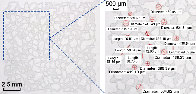
Fig. 2. Microfluidic chip used in microscopic visualization experiments (represents the pores and throats in dark gray, and rock matrix in light gray). |
The core used in the core displacement experiment is low-permeability sandstone outcrop, with measured water permeability of around 10×10−3 µm2, diameter of 3.8 cm and length of 15 cm. The core displacement experiment was operated in a high temperature and high pressure physical simulation system developed by PetroChina Research Institute of Petroleum Exploration & Development (RIPED), and consisting of a Quizix Q5200 pump, a core holder, a back-pressure control system and a gas-liquid collection unit.
1.2. Interfacial tension test
The interfacial tension (IFT) between diluted oil and displacing fluid was measured at 25 °C and rotating speed of 5 000 r/min using a TX-500C interfacial tension meter produced by Beijing Shengwei Technology Co., Ltd. (Beijing), with an error within ±5%.
1.3. Air-liquid-solid contact angle test
The air-liquid-solid contact angle of oil displacing fluid on quartz surface was measured by the sessile drop method in a LAUDA Scientific GmbH machine. First, add 2 μL droplet onto the quartz solid surface using a syringe. Then, the droplet shape was captured by a camera, and the air- liquid-solid contact angle was obtained by analysis in software. The measurement was operated at 25 °C.
1.4. Oil-liquid-solid contact angle test
The measurement was operated in a LAUDA Scientific GmbH machine. The oil displacing fluid was injected into a quartz trough with holder and kept at constant temperature. Inside the incubator, add 2 μL oil droplet onto a clean quartz plate which was then inverted and placed on the holder within the quartz trough. Finally, the oil droplet shape was identified by a camera, and the oil-liquid-solid contact angle was measured through software analysis. The experiment was operated at reservoir temperature, 85 °C, for simulating actual reservoir conditions and ensuring oil mobility.
1.5. Emulsion stability test
The emulsion stability was determined by bottle test with a 5 mL test tube with stopper. Diluted oil and oil displacing fluid were mixed at a volume ratio of 5:5 and then shaken for 100 times until full emulsification. The emulsion was photographed at different times, and the volume of the aqueous phase was recorded for the evaluation of emulsion stability and the calculation of water separation ratio. The water separation ratio is the separated water volume divided by the total water volume. The measurement was operated at 25 °C.
1.6. Zeta potential measurement at oil-water interface
The emulsion sample was diluted by 200 times, and the Zeta potential at the oil-water interface was measured by dynamic light scattering in Malvern Zetasizer Nano ZS. Each sample was measured 3 times and taken the average. The test was operated at 25 °C.
1.7. Microscopically visualized oil displacement experiment
The microscopically visualized oil displacement experiment was carried out in a micro-fluidic chip with simulated pore structures. First, the diluted oil was injected at 20 μL/min until oil filled all pores and throats. The displacing fluid was injected at 0.1 μL/min from the top right inlet using a FLOW-EZ S/N 12490 pump, and oil was expelled from the left bottom outlet. The measurement was not finished until the state of the remaining oil in the model did not change. The displacement process was recorded in a Nikon SMZ18 microscope and software. The injection pressure during displacement was recorded in uProcess Software. The test was operated at 25 °C.
1.8. Core displacement experiment
Core displacement experiment was performed with different displacing fluids in natural sandstone cores with water permeability of 11.48×10⁻³, 13.15×10⁻³ and 9.42×10⁻³ µm2, respectively, following the steps below. (1) The core was evacuated and saturated with formation water, and the volume of saturated water was measured to determine the pore volume (PV). (2) The core was placed in an oven at 85 °C and aged for 24 h. (3) The core was saturated with oil, and the volume of saturated oil and the oil saturation are calculated. After saturation, the core was aged at the formation temperature (85 °C) for additional 24 h. (4) Waterflooding was operated at a constant rate of 0.2 mL/min. Injection pressure and cumulative oil and water production were recorded at the outlet until the water cut was over 98%. (5) Chemical flooding was performed by injecting 0.5 PV of chemical flooding solution at the same flow rate, and injection pressure and cumulative oil and water production were recorded at the outlet. (6) Subsequent waterflooding was operated at the same rate, and injection pressure and cumulative production were recorded at the outlet. (7) The oil recovery at each displacement stage was calculated.
2. Results and discussion
2.1. Interface properties and oil displacement effects of 1OH-1C solution
2.1.1. Interface properties
The IFTs of 1OH-1C and diluted oil are close (Fig. 3a), indicating that 1OH-1C has no interfacial activity and is not adsorbed on the oil-water interface. The measured Zeta potentials of formation water and 1OH-1C at the oil-water interface are slightly different, namely −15.2 mV and −17.2 mV, respectively, confirming that 1OH-1C has no significant effect on the electrical properties of the oil-water interface. The contact angle of 1OH-1C solution on the quartz surface (13.2°) is slightly lower than that of distilled water (18.6°) (Fig. 3b), which indicates that 1OH-1C can be adsorbed on the quartz by hydrogen bonds [17], and increase the negative charge density on the solid surface. The oil-liquid-solid contact angle indicating the state of the oil film on quartz surface (Fig. 3c) shows that the oil film gradually shrinks into an oil droplet with time. The oil-liquid-solid contact angle is controlled by oil-water IFT, quartz-water interfacial free energy, and quartz-oil interfacial free energy. Quartz is a high-energy surface. When formation water displaces air, the quartz-water interfacial free energy reduces sharply, the oil film starts to shrink, and the contact angle increases progressively. When 1OH-1C solution replaces formation water, the contact angle rises from 94° to 116°. This is because that 1OH-1C increases the surface negative charge density, and generating an electrostatic separation pressure with the negatively charged oil [18] and enhancing oil-film shrinkage. The water separation ratio and stability of emulsions formed with 1OH-1C solution and oil are shown in Fig. 3d and Fig. 3e. 1OH-1C solution is not adsorbed at the oil-water interface, and its emulsion behavior is close to that observed in the formation water.
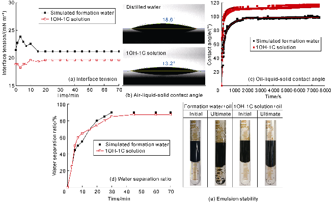
Fig. 3. Interfacial properties of 1OH-1C solution and simulated formation water. |
2.1.2. Microscopic oil displacement effect
During chemical flooding, oil migrates with water as a mixture in reservoir pores, and the migration characteristics dominate the displacement effect [19-21]. Fig. 4 presents the remaining oil distribution, recovery degree, sweep efficiency and displacement efficiency after flooded by simulated formation water and 1OH-1C solution in water-wet and oil-wet models. The purple outline in Fig. 4a defines the swept area of displacing fluids. S1, S2 and S3 denote the oil-saturated area before displacement, the unswept oil area (i.e. the oil-saturated area outside the magenta range), and the remaining oil area after displacement, respectively. The sweep efficiency is [(S1- S2)/S1]×100%, the recovery degree is [(S1-S3)/S1]×100%, and the oil displacement efficiency is defined as the recovery degree within the swept range.
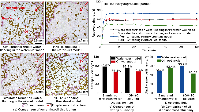
Fig. 4. Displacement effects of simulated formation water and 1OH-1C in water-wet and oil-wet models. |
For simulated formation waterflooding, the recovery degree in the water-wet model is close to that in the oil-wet model, but there is a large difference in remaining oil distribution. In the water-wet model, the sweep efficiency is relatively high (87.8%), and there is substantial clustered remaining oil in the low shear-stress area, resulting in a low displacement efficiency within the swept area (72.3%). In the oil-wet model, the increased difficulty in oil mobilization led to obvious viscous fingering, and the formation of dominant flow path resulted in water channeling and reduction of the sweep efficiency to 68.4%. This is consistent with previous reports on effects of wettability on displacement performance [22].
For 1OH-1C solution flooding, there is a significant difference in oil displacement effects in water-wet and oil-wet models. In the water-wet model, the recovery degree reached 72.1%, 11.7 percentage points higher than that by formation waterflooding. During the same flooding period, numerous, large, continuous clustered remaining oil occurred along the main flow channels within the swept range in the oil-wet model, resulting in a displacement efficiency of only 64.5%, 17.9 percentage points lower than that by formation waterflooding. The ultimate recovery degree is only 44.2%, 13.2 percentage points lower than that by formation waterflooding.
The divergent displacement behaviors of displacing fluids in chips with different wettabilities are primarily due to different interaction between oil and solid surface. In the oil-wet model, strong quartz-oil interaction occurred, such as ionic hydration bridges and hydrophobic forces, and the displacing fluid primarily occupied large pores and throats, thus creating dominant flow paths and reducing the sweep efficiency. In the water-wet model, weak quartz-oil interaction allowed invasion of displacing fluid into smaller pores, resulting high sweep efficiency, but the limited shear couldn't separate oil film from the quartz surface.
2.1.3. Mechanism of microscopic oil displacement
The microscopic oil displacement effects of 1OH-1C solution in water-wet and oil-wet models are shown in Fig. 5. As mentioned above, macroscopic superwetting phenomenon is defined by a contact angle of less than 5°. Superwetting in micro-nano pores is not simply determined by contact angle, but defined by flow characteristics of the aqueous phase during displacement. As shown in Fig. 5, in microfluidic chips, the displacing aqueous phase flowed along the quartz-oil interface and did not break through the oil phase, exhibiting clear superwettable behavior on the solid surface. As shown in Fig. 5a, in the water-wet model, 1OH-1C solution formed a superwettable interface at the quartz-oil interface, stripping off the oil and creating an aqueous phase flow channel between oil and quartz surface. Subsequent fluid flowed through the channel, and the trapped oil was mobilized. Since the quartz-oil interaction has been disrupted, little film-shaped remaining oil was left. As shown in Fig. 5b, in the oil-wet model, 1OH-1C solution also formed an aqueous phase channel by generating the superwetting interface, but nearly all following solution flowed through the channel and migrated along the edges of pores and throats, leaving remaining oil not mobilized. Although the oil film was reduced, some oil remained in isolated patches.
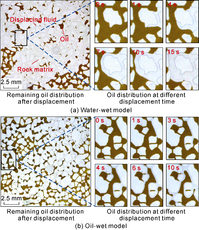
Fig. 5. Mobilization and migration process of oil driven by 1OH-1C solution. |
Hu et al. [23] investigated the method of breaking cationic hydration bridges through molecular dynamics simulation. They proposed that cationic hydration bridges can be broken by using cation exchangers (Na+ replacing Ca2+), cation shielding agents (antioxidants and EDTA) and hydrogen bond disruptors, thereby stripping oil film from quartz surface. Fig. 5 demonstrates that cationic hydration bridges can be broken by forming a superwettable interface.
The injection pressure of simulated formation water and 1OH-1C solution flooding in the simulation model is shown in Fig. 6. In the water-wet model, the variation trend of injection pressure curve during 1OH-1C flooding is similar to that during formation waterflooding, but the threshold pressure is higher by 1OH-1C flooding. However, in the oil-wet model, the threshold pressure by 1OH-1C flooding is significantly lower than that by formation waterflooding. The difference in pressure in two models reflects the effect of the superwettable interface.
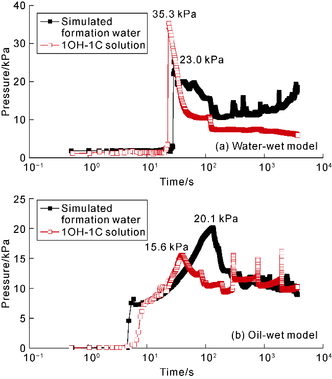
Fig. 6. Injection pressure variation during formation waterflooding and 1OH-1C solution flooding. |
In this study, the microscopic contact angle of remaining oil in the oil-wet model was measured by the following procedures. Select the film-like remaining oil area based on oil displacement results, draw a straight line along the quartz surface edge and a tangent line along the oil-water interface, use PicPick software to measure the angle between them for contact angle of microscopic remaining oil [24]. Measurements were conducted three times, and data were fitted using the Young-Laplace equation with an error within ±2°. The contact angles of film-like remaining oil showed significant differences after simulation of formation waterflooding and 1OH-1C flooding (Fig. 7). After formation waterflooding, lots of thin oil films were left on the solid surface with contact angles around 35°. After 1OH-1C flooding, the contact angles are mostly between 50° and 60°, reflecting the effect of electrostatic separation pressure. Microscopic remaining oil occurs in clustered, porous, columnar, film-like and droplet shapes [25]. Clustered remaining oil is a continuous phase across pore throats. Porous remaining oil exists as a discontinuous phase in 1-5 pore throats. Columnar remaining oil is a discontinuous phase in a single pore-throat. Droplet-shaped remaining oil is a discontinuous phase in a single pore and does not contact the rock skeleton. Film-like remaining oil is adsorbed on pore walls as oil films with thickness smaller than the pore-throat radius.
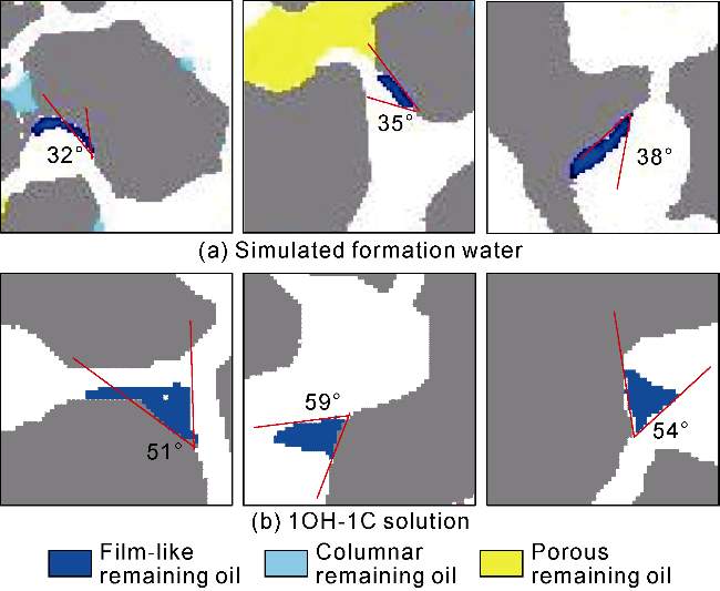
Fig. 7. Microscopic contact angles during formation waterflooding and 1OH-1C-solution flooding in the oil-wet model (rock matrix in gray, displacing fluid in white). |
2.2. Interfacial properties and oil displacement performance of S-C13PO13S solution
2.2.1. Interfacial properties
The interfacial properties of S-C13PO13S solution are shown in Fig. 8. The dynamic IFT between S-C13PO13S and oil gradually decreased and reached an order of 1×10⁻² mN/m as shown in Fig. 8a. The excellent interfacial activity of S-C13PO13S is due to its long PO chain which has a size compatible with its hydrophilic group [15]. He et al. [26] proposed that the long PO chain of the extended surfactant adjusts the hydrophobic group size to achieve an ultra-low IFT by curling into a spiral at the oil-water interface uniformly. In Fig. 8b, the air-liquid-solid contact angle of S-C13PO13S solution on the quartz surface is significantly smaller than that of distilled water. This indicates that S-C13PO13S reduces the surface tension significantly [27]. The oil-liquid-solid contact angles indicate that S-C13PO13S molecules are adsorbed at the oil-water interface, and the anionic heads towards the aqueous phase increase the negative charge density at the interface significantly (Fig. 8c). These negative charges generate a larger electrostatic separation pressure near the three- phase point and increase the oil-liquid-solid contact angle rapidly to 125°, which is conductive to oil film separation [5]. Zeta potential measurement at the oil-water interface shows −15.2 mV for simulated formation water and −58.6 mV for S-C13PO13S solution, confirming that S-C13PO13S enhances electrostatic interaction significantly. Fig. 8d shows that S-C13PO13S emulsion cannot provide water separation within 60 min. This is due to the helical structure in the molecule with stored energy that can deform in response to interface disturbances, thus increasing the strength of the interfacial film and improving the emulsion stability (Fig. 8e). Tagavifar et al. [28] reported the kinetic behavior of C13-PO13-SO4 in micro-emulsion that is formed intermediately as C13-PO13-SO4 solution contacts with oil.
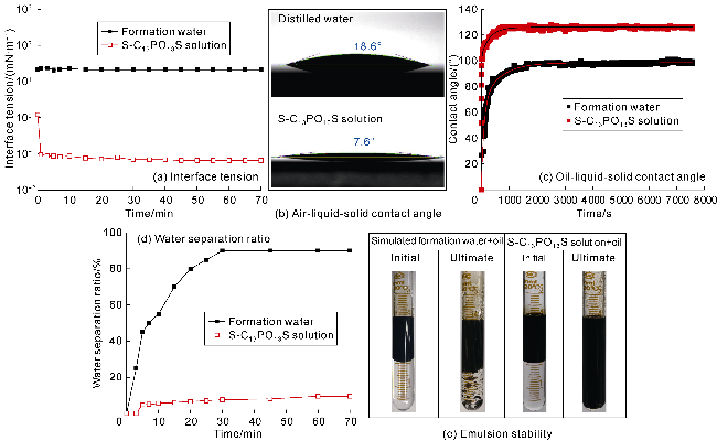
Fig. 8. Interfacial properties of S-C13PO13S solution and simulated formation water. |
2.2.2. Effects of microscopic oil displacement
The oil displacement effects of simulated formation waterflooding and S-C13PO13S flooding in the oil-wet model are shown in Fig. 9. It is found that S-C13PO13S achieved oil recovery of 66.7%, sweep efficiency of 81.8% and oil displacement efficiency of 82.9% within 60 min. Compared with simulated formation waterflooding, S-C13PO13S solution flooding reduced columnar and porous remaining oil and achieved higher sweep efficiency, but leaving droplet, film-like and clustered remaining oil.
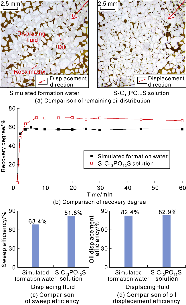
Fig. 9. Comparison of displacement effects of simulated formation water flooding and S-C13PO13S solution flooding in the oil-wet model. |
2.2.3. Mechanism of microscopic oil displacement
Oil emulsion by surfactant is a vital mechanism for EOR. Wang et al. [29] reported that surfactants can cause reduction of oil-water IFT, emulsify the crude oil and create plugging within pore-throat, thereby improving sweep efficiency. Shang et al. [30] investigated the displacement performance and microscopic mechanisms of surfactant/alkaline flooding system on simulated chips, and found that emulsion can enlarge the sweep efficiency by aggregation and enhance the oil displacement efficiency by carrying oil, leading to a substantial increase in recovery.
The microscopic oil displacement effect of S-C13PO13S in the oil-wet model is shown in Fig. 10. Due to the relatively low IFT, oil was drawn into filaments under the shear stress of the displacing fluid, which were then broke into oil-in-water emulsions. Numerous, droplets heterogeneous in size were gradually carried forward in the flow direction, enhancing the oil displacement efficiency. After the droplets became enough, the blocking effect was generated at pore-throat entry due to the accumulation of droplets (Fig. 10a), thereby increasing the sweep efficiency [31]. In addition, the polyoxyethylene and polyoxypropylene chains in the molecular structure significantly strengthened the oil-water interfacial film. As a result, the droplets formed when the solution contact with oil exhibit a high stability and certain deformation capacity (Fig. 10b). Moreover, the droplets larger than throats plugged the throats via the Jamin effect and increased the sweep efficiency.
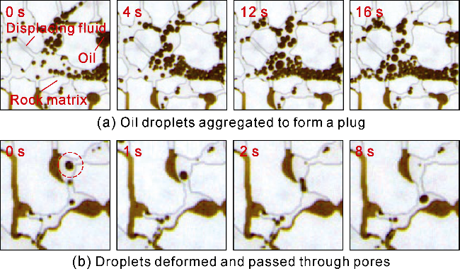
Fig. 10. Oil migration characteristics during S-C13PO13S solution flooding in the oil-wet model. |
The dynamic pressure curve in Fig. 11a indicates that the relatively low IFT results in lower threshold pressure driving oil mobilization by S-C13PO13S solution. The curve is divided into three stages. (1) The pressure rose due to oil emulsification, then kept increasing until a peak as the emulsification area expanded. (2) The pressure remained high due to Jamin and plugging effects with the migration of emulsified droplets. (3) The pressure was stabilized at a lower equilibrium value as the solution flowed through the main channels and emulsification became weak [32]. Additionally, the microscopic contact angle of crude oil in Fig. 11b shows that the contact angle of film-like remaining oil increased significantly to 60°- 90° due to emulsification-induced stripping and electrostatic separation pressure.
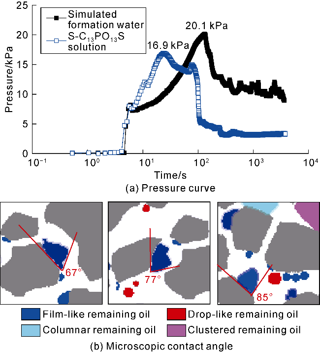
Fig. 11. Pressure curve and microscopic contact angle during S-C13PO13S solution flooding in the oil-wet model (rock skeleton in gray, and displacing solution in white). |
2.3. Synergistic effect of 1OH-1C and S-C13PO13S
2.3.1. Interfacial properties
Fig. 12a shows the IFTs of different displacing fluids. The IFT of the compound system is close to that of S-C13PO13S solution. Moreover, the interfacial potentials of S-C13PO13S solution and the compound system are −58.6 mV and −60.8 mV, with a little difference. In Fig. 12b, the air-liquid-solid contact angle of the compound system reduced to 4.2°, which indicates a superwettable state due to the superimposed effect of hydrophilic modification of 1OH-1C and reduction of surface tension by S-C13PO13S. Fig. 12c shows that the compound system has a higher oil-liquid-solid contact angle and a better ability to strip oil films than the single solution system. Fig. 12d and 12e reveal that the emulsion produced by the compound system exhibits excellent stability, which is conductive to emulsifying and transporting oil within pores, thereby enhancing oil recovery.
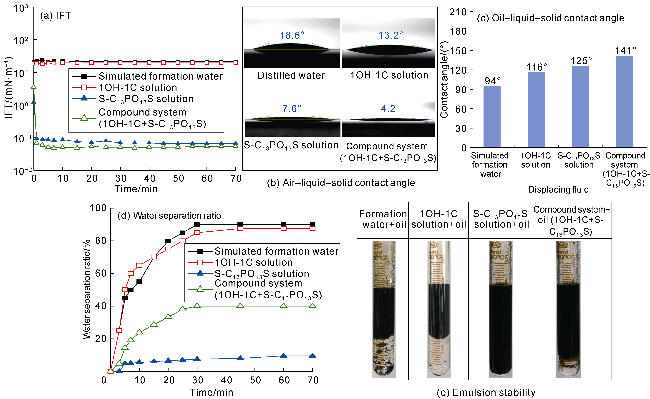
Fig. 12. Interfacial properties of different displacing fluids. |
2.3.2. Effects of microscopic oil displacement
The oil displacement effects of simulated formation water, 1OH-1C, S-C13PO13S and compound system in the oil-wet model are shown in Fig. 13. It is observed from the remaining oil distribution that the compound system has a better oil displacement capacity (Fig. 13a). The oil recovery degree of different displacing fluids within 60 min is ranked in ascending order as 1OH-1C, formation water, S-C13PO13S, compound system. The recovery degree of the compound system increased by 23.2 percentage points compared with that by simulated formation water flooding (Fig. 13b). Particularly, the sweep efficiency and oil displacement efficiency of the compound system are 84.3% and 95.4% (Fig. 13c and 13d), which are much higher than those of formation water, 1OH-1C and S-C13PO13S solutions. The reason is that clustered remaining oil reduces significantly after flooding by the compound system. Clustered remaining oil, caused by local microscopic heterogeneity in pore structure, occupies the largest proportion of remaining oil and is the most difficult type to produce [33-34]. Continuous clustered remaining oil accounts for only 10.8% of the whole remaining oil (Fig. 13e) after compound system flooding. This indicates that the compound system has a strong ability to mobilize clustered remaining oil.
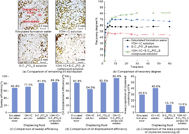
Fig. 13. Oil displacement effects of different solutions in the oil-wet model. |
2.3.3. Synergistic oil displacement mechanism
Microscopic features of oil displacement with different solutions in the oil-wet model are shown in Fig. 14. During simulated formation water flooding or 1OH-1C solution flooding (Fig. 14a, 14b), oil retained in pores with relatively large throats was displaced, but the solution bypassed the pores with smaller throats, leaving continuous clustered remaining oil. The direction of throats where oil was left is almost perpendicular to the major flow direction. Such remaining oil experienced the least disturbance, and it is the most difficult type to be displaced [34]. Even with low IFT and strong emulsifying property, some clustered remaining oil in the throats perpendicular to the major flow direction has not been mobilized after flooded by S-C13PO13S solution (Fig. 14c). In contrast, when flooded by the compound system (Fig. 14d), the interfacial superwetting phenomenon occurred firstly in oil-saturated pores, and 1OH-1C disrupted the solid-oil interface. Then, S-C13PO13S was adsorbed on the oil-water interface, and anionic groups of S-C13PO13S enhanced electrostatic repulsion between the oil film and the quartz surface, further shrinking and stripping off the oil film. Clustered remaining oil was mobilized and transported as filaments under the shear stress of the displacing fluid. Ultimately, clustered oil originally perpendicular to the major flow direction was mobilized through synergistic modification at the solid-oil and oil-water interfaces.
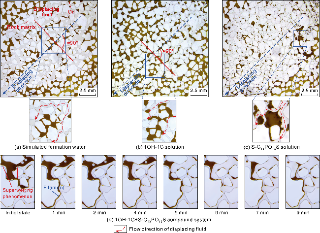
Fig. 14. Remaining oil distribution after flooded by different solutions in the oil wet model and the process of mobilizing clustered remaining oil by the compound system. |
Fig. 15a shows that the pressure curve of the compound system has a higher initial pressure than the single solutions. This is due to the disruption of solid-oil interface and oil separation by 1OH-1C and mobilization and emulsification of isolated remaining oil by S-C13PO13S. Moreover, the contact angles of film-like remaining oil in the compounded system are larger than those in the single solutions, most of which are more than 90° (Fig. 15b). Under a weak shear action, the compound system has a superwettability to disrupt solid-oil interaction and strip oil films, and works as a surfactant to reduce IFT and emulsify oil. This synergistic effect on solid-oil interface and oil-water interface results in maximum recovery of clustered remaining oil within the swept area and significant improvement of EOR.
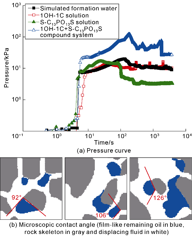
Fig. 15. Pressure curve and microscopic contact angle duirng 1OH-1C+S-C13PO13S compound system flooding in the oil-wet model. |
2.3.4. Core flooding effects
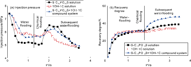
Fig. 16 presents the injection pressure and recovery change with injected PVs during oil displacement experiments on cores by S-C13PO13S solution, 1OH-1C solution and 1OH-1C +S-C13PO13S compound system. The injection pressure rose as oil was mobilized (Fig. 16a). The maximum pressure increases are 1.36, 0.37 and 0.61 MPa by S-C13PO13S solution, 1OH-1C solution and the compound system respectively, with the lowest pressure increment by 1OH-1C flooding. After shifting to waterflooding, the pressure declined gradually. The pressure drop is ranked in descending order of 1OH-1C solution, the compound system, S-C13PO13S solution. This is because that 1OH-1C disrupts the oil-rock interaction and forms the interfacial superwettability that enhances microscopic flow in the pores, which is consistent with the microscopic visualization experiment result. S-C13PO13S causes emulsification and mobilization of additional oil, and emulsified oil droplets increase flow resistance, which induces a slow pressure drop. The compound system has both effects of the single systems, so the pressure decline is moderate. Fig. 16b indicates that, based on waterflooding, S-C13PO13S flooding enhanced oil recovery by 7.3 percentage points due to low interfacial tension and emulsification, 1OH-1C flooding increased by 3.1 percentage points due to weakened oil-rock interaction, and the compound system by 16.4 percentage points due to synergistic modification on oil-water and oil-rock interfaces.
Fig. 16. The variation of injection pressure and oil recovery with injection volume during the core flooding process of different solutions. |
3. Conclusions
The 1OH-1C is adsorbed on the quartz surface through hydrogen bonds and causes reduction of the free energy on the solid-liquid interface, increase of negative charges on the solid surface, and electrostatic separation pressure created near the three-phase point. The electrostatic separation pressure increases the oil-water-solid contact angle, which is beneficial to strip off oil films. In the microfluidic chip, a superwettable interface formed between the polar solid surface and the oil film, and the remaining oil film attached to the quartz surface is stripped. 1OH-1C has a promising prospect for mobilizing film-like remaining oil, but the remaining oil is hard to migrate.
S-C13PO13S has excellent interfacial properties, emulsification ability and the ability to strip oil films, and it reduces oil-water IFT to an order of 1×10⁻² mN/m, increases capillary number and emulsifies oil. Moreover, it increases negative charge density and three-phase contact angle by adsorbing on oil-water interface. The oil displacement mechanisms involve emulsifying and stripping oil for enhancing oil displacement efficiency, deformation, Jamin effect and blocking effect of emulsified droplets for improving sweeping efficiency.
The compound system of 1OH-1C and S-C13PO13S has an excellent interfacial activity, and capabilities of wettability alteration, stripping oil films, and oil emulsification. Under the synergistic effect, 1OH-1C creates a superwettable interface which disrupts solid-oil interaction and stripping off the oil film. S-C13PO13S adsorbed on oil-water interface improves the hydrophilicity of solid surface and is helpful to stripping oil films, reducing interfacial tension, improving oil emulsification, enlarging swept range and mobilizing and transporting the remaining oil. The compound system improves oil recovery through the synergistic effect of wettability alteration on oil-solid and oil-water interfaces.
The compound system with an excellent superwettability is cost-effective and environmentally friendly, especially for low-permeability and shale oil reservoirs where rock-oil interfacial interaction controls the EOR by chemical flooding. Future research should focus on how the interaction between hydroxyl anions and surfactants affects their individual performances and how oil-water interfacial film properties affect the superwettability.