


Introduction
Cluster wells are widely used in offshore and land drilling, which can save the cost of oil and gas development, cut down the occupation of land resource and reduce the environmental pollution. With the development of oil fields, cluster wells and infill wells are increasing in number and densely distributed, setting higher requirements for collision avoidance technology. China has established industry standards on wellbore collision avoidance[1]. The Industry Steering Committee on Wellbore Survey Accuracy (ISCWSA) has also been committed to this task long[2]. Anti-collision technology is mainly used in well-path planning and real-time monitoring of cluster wells, infill wells and directional wells. It can be used to evaluate the rationality of well-path planning or to monitor the contact between the bit and the adjacent well in real time to warn risk early.
The evaluation method of wellbore collision avoidance is based on well distance scanning and trajectory measurement error analysis. The evaluation indicators include the minimum distance to the adjacent well[3,4], wellbore separation factor[3,5-16], and collision probability of wellbores[3, 17-19] etc. Among these indicators, wellbore separation factor considers both the distance to the adjacent well and error of the trajectory, so its evaluation result is more reliable than the minimum distance to the adjacent well, and it is simpler to calculate than collision probability of wellbores, therefore, it is a widely-used evaluation indicator at home and abroad. The existing calculation methods of wellbore separation factor mainly include the traditional separation factor method, central vector method[3, 13], pedal curve method[3, 13], directional separation factor method[6-10, 12, 14, 16], ellipsoid scaling method[13, 20] and minimum distance method[21] etc.
According to the research, the evaluation results of traditional separation factor method and pedal curve method are too conservative[3, 13], while the evaluation results of central vector method and directional separation factor method are too optimistic[3, 13, 20]. The ellipsoid scaling method and minimum distance method can obtain more objective evaluation results[13, 20-21] but still have deficiencies in theoretical completeness and calculation accuracy. In the aspect of the theoretical completeness, the existing methods calculate the trajectory coordinates and error ellipsoid independently, and then study the relationship between the relative position and geometry of the error ellipsoids of adjacent wells, without considering the correlation of trajectory errors between adjacent wells. In terms of the calculation accuracy, the distance scanning methods of adjacent wells (normal distance scan, minimum distance scan and horizontal distance scan etc.) are adopted to establish the corresponding relationship of trajectory depth, calculate the separation factor at every depth and then sort out the minimum factor. But the minimum value obtained by this method is not necessarily the global minimum. In order to improve the theoretical model and raise the calculation accuracy, we put forward the theoretical formula and algorithm of separation factor based on the relative position of adjacent wells, relative position method for short, which considers the correlation of trajectory error of adjacent wells and solves the global minimum by conjugate gradient method. It is expected that this method can evaluate the level of spatial separation between adjacent wells more objectively, and better meet the demand of well-path planning and anti-collision analysis of dense cluster wells.
1. Computing method
There are three steps to calculate the wellbore separation factor. First, calculate the well trajectory and trajectory uncertainty of the comparison and reference wells respectively. Second, calculate the relative position and uncertainty thereof from the comparison well to the reference well. Third, calculate the wellbore separation factor between the comparison well and the reference well.
1.1. Trajectory and trajectory uncertainty of the single well
Taking the north-east-down coordinate system as the global coordinate system, the minimum curvature method is adopted to calculate the well trajectory coordinates according to the industry standards at home and abroad[22,23]. As shown in Fig. 1, the investigation point is located between the survey point K-1 and the survey point K of the well trajectory, and its coordinates are expressed as:
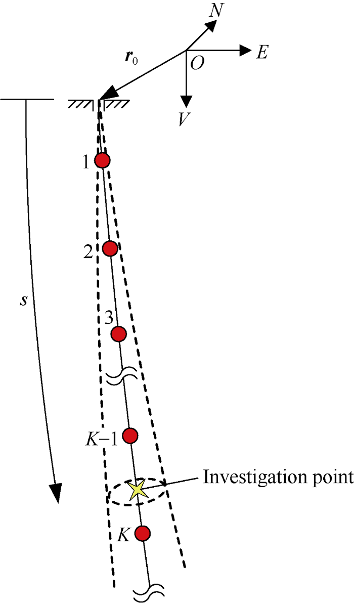
Fig. 1.
Schematic of the trajectory of the single well and its uncertainty.
where ${{\mathbf{\tau }}_{k}}={{\left[ \begin{matrix}\sin {{I}_{k}}\cos {{A}_{k}} & \sin {{I}_{k}}\sin {{A}_{k}} & \cos {{I}_{k}} \\\end{matrix} \right]}^{\text{T}}}$
(k=1, 2, ..., K)
$\Delta {{L}_{k}}={{L}_{k}}-{{L}_{k-1}}$
${{\mathbf{r}}_{k}}={{\mathbf{r}}_{0}}+\sum\limits_{j=1}^{k}{\Delta {{L}_{j}}\left( {{\mathbf{\tau }}_{j-1}}+{{\mathbf{\tau }}_{j}} \right){\tan \left( {{\theta }_{j}}/2 \right)}/{{{\theta }_{j}}}\;}$
${{\theta }_{k}}=\arccos \left( \mathbf{\tau }_{k-1}^{\text{T}}{{\mathbf{\tau }}_{k}} \right)$
$U={\left[ \cos \left( {{\theta }_{K}}-\xi {{\theta }_{K}} \right)-\cos {{\theta }_{K}} \right]}/{\left( {{\theta }_{K}}\sin {{\theta }_{K}} \right)}\;$
$V={\left[ 1-\cos \left( \xi {{\theta }_{K}} \right) \right]}/{\left( {{\theta }_{K}}\sin {{\theta }_{K}} \right)}\;$
$\xi ={\left( s-{{L}_{K-1}} \right)}/{\Delta {{L}_{K}}}\;$
Balanced tangential method is adopted to calculate the trajectory uncertainty for convenience of calculation. According to previous research, calculating the trajectory uncertainty based on balanced tangential method can guarantee the calculation accuracy[11]. The coordinates of any point on the trajectory are functions of the wellhead coordinates, the data of the survey points and the local coordinates of the investigation point. The errors of wellhead coordinates and local coordinates of the investigation point are ignored, and the error model of the ISCWSA is adopted for the survey data error[2], then the error of the trajectory coordinates is expressed as:
where ${{\mathbf{e}}_{i,k}}=\frac{\partial \mathbf{r}}{\partial {{\mathbf{p}}_{k}}}\frac{\partial {{\mathbf{p}}_{k}}}{\partial {{\varepsilon }_{i}}}{{\sigma }_{i,k}}$ $\frac{\partial \mathbf{r}}{\partial {{\mathbf{p}}_{k}}}=\left[ \begin{matrix}\frac{\partial \mathbf{r}}{\partial {{L}_{k}}} & \frac{\partial \mathbf{r}}{\partial {{I}_{k}}} & \frac{\partial \mathbf{r}}{\partial {{A}_{k}}} \\\end{matrix} \right]$
$\frac{\partial \mathbf{r}}{\partial {{L}_{k}}}=\frac{1}{2}\left\{ \begin{align}& \left( {{\mathbf{\tau }}_{k-1}}-{{\mathbf{\tau }}_{k+1}} \right)\quad k<K-1 \\& \left[ {{\mathbf{\tau }}_{K-2}}-\xi {{\mathbf{\tau }}_{K-1}}+\left( 1-\xi \right){{\mathbf{\tau }}_{K}} \right]\ k=K-1 \\& \xi \left( {{\mathbf{\tau }}_{K-1}}+{{\mathbf{\tau }}_{K}} \right)\quad k=K \\\end{align} \right.$
$\frac{\partial \mathbf{r}}{\partial {{I}_{k}}}=\frac{\partial {{\mathbf{\tau }}_{k}}}{\partial {{I}_{k}}}\left\{ \begin{align}& \left( {{L}_{k+1}}-{{L}_{k-1}} \right)k<K-1 \\& \left( s-{{L}_{k-1}} \right)k=K-1,K \\\end{align} \right.$
$\frac{\partial \mathbf{r}}{\partial {{A}_{k}}}=\frac{\partial {{\mathbf{\tau }}_{k}}}{\partial {{A}_{k}}}\left\{ \begin{align}& \left( {{L}_{k+1}}-{{L}_{k-1}} \right)k<K-1 \\& \left( s-{{L}_{k-1}} \right)k=K-1,K \\\end{align} \right.$
$\frac{\partial {{\mathbf{\tau }}_{k}}}{\partial {{I}_{k}}}={{\left[ \begin{matrix}\cos {{I}_{k}}\cos {{A}_{k}} & \cos {{I}_{k}}\sin {{A}_{k}} & -\sin {{I}_{k}} \\\end{matrix} \right]}^{\text{T}}}$
$\frac{\partial {{\mathbf{\tau }}_{k}}}{\partial {{A}_{k}}}={{\left[ \begin{matrix}-\sin {{I}_{k}}\sin {{A}_{k}} & \sin {{I}_{k}}\cos {{A}_{k}} & 0 \\\end{matrix} \right]}^{\text{T}}}$
There are five types of survey error terms: random error, systematic error, well-by-well error, global error and survey bias[11]. The error types are differentiated for the convenience of calculating the correlation between random variables. The correlation coefficients of these five error types are shown in Table 1.
Table 1 Correlation coefficients of random variables corresponding to five types of error terms.
| Type | Conditions | Correlation coefficient |
|---|---|---|
| Random error | Same error term in the same well | 0 |
| Same error term in different wells | 0 | |
| Different error terms | 0 | |
| Systematic error | Same error term in the same well with the same measurement tool | 1 |
| Same error term in the same well with different measurement tools | 0 | |
| Same error term in different wells | 0 | |
| Different error terms | 0 | |
| Well-by- well error | Same error term in the same well | 1 |
| Same error term in different wells | 0 | |
| Different error terms | 0 | |
| Global error | Same error term in the same well | 1 |
| Same error term in different wells | 1 | |
| Different error terms | 0 | |
| Survey bias | Same error term in the same well | 1 |
| Same error term in different wells | 1 | |
| Different error terms | 1 |
Referring to some theorems of random mathematics, δr is a random vector with three dimensions which meets the rule of 3-D Gaussian distribution. Its equivalent surface of probability distribution is an ellipsoid, the characteristic matrix of the ellipsoid is the covariance matrix of δr[11], and is expressed as:
where $\mathbf{C}_{\text{rand}}^{{}}=\sum\limits_{i\in R}{\sum\limits_{k}{{{\mathbf{e}}_{i,k}}\mathbf{e}_{i,k}^{\text{T}}}}$
$\mathbf{C}_{\text{syst}}^{{}}=\sum\limits_{i\in S}{\sum\limits_{S}{\left[ \left( \sum\limits_{\forall S}{{{\mathbf{e}}_{i,k}}} \right){{\left( \sum\limits_{\forall S}{{{\mathbf{e}}_{i,k}}} \right)}^{\text{T}}} \right]}}$
$\mathbf{C}_{\text{well}}^{{}}=\sum\limits_{i\in W}{\left[ \left( \sum\limits_{k}{{{\mathbf{e}}_{i,k}}} \right){{\left( \sum\limits_{k}{{{\mathbf{e}}_{i,k}}} \right)}^{\text{T}}} \right]}$
$\mathbf{C}_{\text{glob}}^{{}}=\sum\limits_{i\in G}{\left[ \left( \sum\limits_{k}{{{\mathbf{e}}_{i,k}}} \right){{\left( \sum\limits_{k}{{{\mathbf{e}}_{i,k}}} \right)}^{\text{T}}} \right]}$
$\mathbf{C}_{\text{bias}}^{{}}=\left( \sum\limits_{i\in B}{\sum\limits_{k}{{{\mathbf{e}}_{i,k}}}} \right){{\left( \sum\limits_{i\in B}{\sum\limits_{k}{{{\mathbf{e}}_{i,k}}}} \right)}^{\text{T}}}$
In the Eq. (3), there are particularities in the calculation of covariance matrix of the systematic error. It needs to be accumulated according to the measurement tools. First, accumulate all the error vectors of the same measurement tool. Second, calculate the covariance matrix of all survey points of the same measurement tool. Last, accumulate the covariance matrix of all measurement tools.
The corresponding equation of well trajectory error ellipsoid is defined as:
The ellipsoid scale factor λ is correlated with the confidence probability Pb[17]:
The Eq. (5) can be calculated by numerical integration. Ellipsoid scale factors 1.0, 1.5, 2.0, 2.5, 3.0 and 4.0 correspond to the confidence probabilities of 19.9%, 47.8%, 73.9%, 90.0%, 97.1% and 99.9% respectively. The ellipsoid scale factor usually takes 2.0-3.0 in the error analysis of well trajectory, while it is 2.5 in this study, which means the probability of wellbore position sitting in the error ellipsoid is about 90%.
1.2. Relative position of the adjacent wells and the uncertainty
By using the Eq. (1), the coordinates of the investigation points on the comparison well r1 and on the reference well r2 are calculated, as shown in Fig. 2. Then the relative position of the comparison well to the reference well is expressed as:
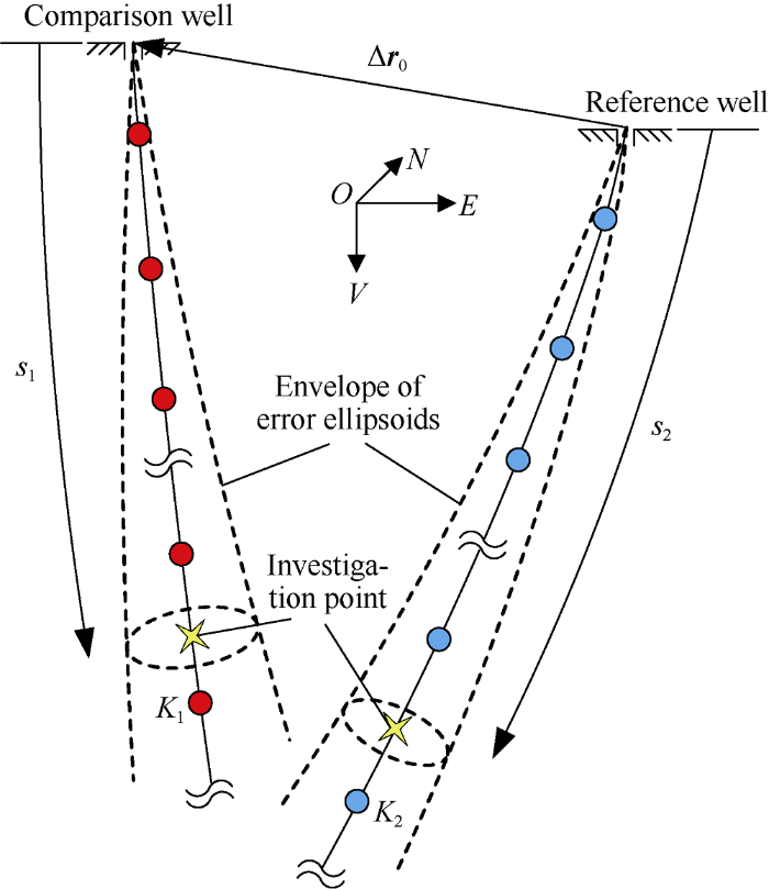
Fig. 2.
Schematic of the relative position of the adjacent wells and its uncertainty.
According to the error model of the ISCWSA, the error of relative position meets the rule of 3-D Gaussian distribution too. Its equivalent surface of probability distribution is also an ellipsoid, and the covariance matrix of the ellipsoid[11] is expressed as:
In Eq. (7), C1(s1) and C2(s2) are calculated according to Eq. (3), while Dglob and Dbias are calculated by the following equations:
where ${{d}_{\text{s}}}={\left( {{D}_{1}}+{{D}_{2}} \right)}/{2}\;+{{d}_{0}}$
The separation factor between the comparison well and the reference well is the global minimum of Eq. (10), which is defined by:
1.3. Solving method for the separation factor
The calculation formula of wellbore separation factor by relative position method is Eq (11), which is a two-dimensional nonlinear minimum problem and can be solved by conjugate gradient method. The objective function is defined as:
The gradient of objective function is derived with Richard extrapolation, and written as:
where
$\frac{\partial f}{\partial {{s}_{1}}}\approx \frac{1}{6h}\left[ 8f\left( {{s}_{1}}+h,{{s}_{2}} \right)-f\left( {{s}_{1}}+2h,{{s}_{2}} \right)-7f\left( {{s}_{1}},{{s}_{2}} \right) \right]$
$\frac{\partial f}{\partial {{s}_{2}}}\approx \frac{1}{6h}\left[ 8f\left( {{s}_{1}},{{s}_{2}}+h \right)-f\left( {{s}_{1}},{{s}_{2}}+2h \right)-7f\left( {{s}_{1}},{{s}_{2}} \right) \right]$
The calculation procedure of wellbore separation factor by relative position method is shown in Fig. 3. In order to locate the global minimum position preliminarily, a scanning search of the whole well section is carried out first, and the minimum in the scanning result is taken as the initial value for the conjugate gradient method. Generally, the scanning interval is 30 m. However, it is necessary to reduce the interval in some special well sections with drastic changes. In the calculation, the conjugate gradient method is the main process, while the forward-backward method and Fibonacci sequence method are combined into one-dimensional search algorithm. Since the range of the minimum value can be detected quickly by the forward-backward method and Fibonacci sequence method can locate the minimum value quickly and accurately. The one-dimensional search algorithm combining the two has the advantages of strong stability, fast search speed and high calculation accuracy.
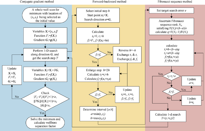
Fig. 3.
Calculation procedure of wellbore separation factor by relative position method.
1.4. Scanning method for minimum separation factor
In the whole well scanning search, the minimum separation factor scanning method is recommended in order to detect the global minimum value quickly. The mathematical problem of this scanning method is how to find the point in the reference well corresponding to the selected point in the comparison well which have the minimum separation factor, and is written as:
This problem is directly solved by the 1-D search algorithm shown in Fig. 3.
2. Examples
2.1. Example 1
An oil field is developed with three-dimensional cluster horizontal wells. The coordinate deviation of the wellhead of the comparison and reference wells, ΔN0 is equal to 4.10 m, ΔE0 is equal to 9.10 m and ΔV0 is equal to 0.09 m. The reference well had one design, while the comparison well had two designs. Their well-path planning data is shown in Table 2. MWD (measurement while drilling) was used for trajectory monitoring. The calculation model included 25 terms of error sources[24], the ellipsoid scale factor was taken as 2.5, and the well diameter and anti-collision safety allowance were ignored.
Table 2 Well-path planning data and error ellipsoids.
| Well name | Well depth/m | Inclination angle/(°) | Azimuth angle/(°) | TVD/m | NS/m | EW/m | Axis half-length of error ellipsoids/m | Euler attitude angle/(°) | ||||
|---|---|---|---|---|---|---|---|---|---|---|---|---|
| Axis 1 | Axis 2 | Axis 3 | Angle 1 | Angle 2 | Angle 3 | |||||||
| Reference well | 486.00 | 0 | 0 | 486.00 | 0 | 0 | 2.11 | 2.11 | 1.12 | 0 | 0 | 0 |
| 721.22 | 47.06 | 27.26 | 695.65 | 81.15 | 41.81 | 3.13 | 3.95 | 1.29 | -28.85 | -5.40 | 2.69 | |
| 801.22 | 47.06 | 27.26 | 750.15 | 133.21 | 68.64 | 3.46 | 5.43 | 1.48 | -28.64 | -10.82 | 5.59 | |
| 1 153.09 | 89.96 | 90.00 | 887.90 | 264.66 | 338.37 | 17.65 | 5.33 | 2.82 | 25.11 | -19.94 | 34.53 | |
| 2 153.09 | 89.96 | 90.00 | 888.59 | 264.66 | 1 338.36 | 69.25 | 5.43 | 13.68 | 7.03 | 0.64 | -7.96 | |
| Comparison Well A | 508.00 | 0 | 0 | 508.00 | 0 | 0 | 2.21 | 2.21 | 1.14 | 0 | 0 | 0 |
| 753.50 | 49.09 | 18.86 | 724.55 | 93.58 | 31.97 | 3.27 | 4.09 | 1.32 | -20.19 | -6.22 | 2.07 | |
| 833.50 | 49.09 | 18.86 | 776.94 | 150.80 | 51.51 | 3.59 | 5.49 | 1.53 | -20.03 | -12.04 | 4.13 | |
| 1 212.81 | 89.98 | 90.00 | 923.22 | 310.46 | 329.30 | 17.90 | 5.71 | 3.16 | 28.22 | -21.77 | 32.93 | |
| 2 212.81 | 89.98 | 90.00 | 923.56 | 310.46 | 1 329.30 | 69.02 | 6.12 | 13.99 | 7.71 | 0.62 | -7.52 | |
| Comparison Well B | 549.59 | 0 | 0 | 549.59 | 0 | 0 | 2.40 | 2.40 | 1.18 | 0 | 0 | 0 |
| 789.71 | 48.02 | 143.78 | 762.57 | -76.54 | 56.06 | 3.38 | 4.25 | 1.37 | 37.25 | 4.38 | 3.47 | |
| 869.71 | 48.02 | 143.78 | 816.08 | -124.51 | 91.20 | 3.68 | 5.77 | 1.58 | 37.15 | 8.97 | 6.94 | |
| 1 188.28 | 89.69 | 90.00 | 936.12 | -231.28 | 347.41 | 16.88 | 5.25 | 2.79 | -23.29 | 17.17 | 33.56 | |
| 2 188.28 | 89.69 | 90.00 | 941.53 | -231.28 | 1 347.39 | 68.85 | 5.25 | 13.53 | -6.11 | -0.76 | -8.59 | |
Based on the key points of well-path planning in Table 2, the coordinates and uncertainty of each survey point were calculated at the survey segment length of 30 m. Due to space limitation, only the coordinates of the key points, the length of the half axis of error ellipsoids and the Euler angle of attitudes are listed in this paper, as shown in Table 2. When calculating the separation factor between wells, a full well scan was performed first at step length of 30 m, the position with the minimum separation factor was taken as the initial value of conjugate gradient method, and calculation was done following the process shown in Fig. 3.
In reference [20], the analysis results of equivalent error ellipsoid method, central vector method, ellipsoid scaling method and traditional separation factor method were compared, which showed that the result of traditional separation factor method was too conservative, the results of equivalent error ellipsoid method and central vector method were too optimistic, and the result of ellipsoid scaling method was in between. In reference [21], the analysis results of directional separation factor method, central vector method, minimum distance method, pedal curve method and traditional separation factor method were compared. It was concluded that the results of central vector method and directional separation factor method were slightly optimistic, the results of traditional separation factor method and pedal curve method were conservative, and the result of minimum distance method was in the middle of these five methods. By reviewing the above literatures, it is considered that ellipsoid scaling method and minimum distance method can obtain more objective evaluation results. Therefore, in this study the results of relative position method, ellipsoid scaling method and minimum distance method were compared further. The wellbore separation factor was calculated by these three methods respectively, the results are shown as Table 3, Figs. 4 and 5. The following conclusions can be drawn: (1) The results of the three methods are close in general, but the results of ellipsoid scaling method and minimum distance method are still slightly conservative. (2) When the error ellipsoids do not intersect, the results of ellipsoid scaling method and minimum distance method are consistent; when the error ellipsoids intersect, the minimum distance method fails, with the separation factor equaling to 1, while ellipsoid scaling method is still effective. (3) Using the minimum distance scanning, the ellipsoid scaling method and minimum distance method may have rapid changes in separation factor with depth, as shown in Fig. 5 at well depth 1183 m. In contrast, the relative position method adopts the minimum separation factor scanning, so the separation factor from this method changes continuously with well depth. In summary, it is concluded that compared with the ellipsoid scaling method and minimum distance method, the relative position method can evaluate the wellbore contact state more accurately, and is more applicable, and more rational.
Table 3 Comparison of calculation results of the ellipsoid scaling method, minimum distance method and relative position method.
| Well name | Separation factor with the reference well | ||
|---|---|---|---|
| Ellipsoid scaling method | Minimum distance method | Relative position method | |
| Comparison well A | 0.76 | 1.00* | 1.03 |
| Comparison well B | 1.29 | 1.29 | 1.83 |
Note: "*" indicates that the method is invalid under current application conditions
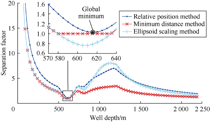
Fig. 4.
Well separation factor between the comparison well A and the reference well.
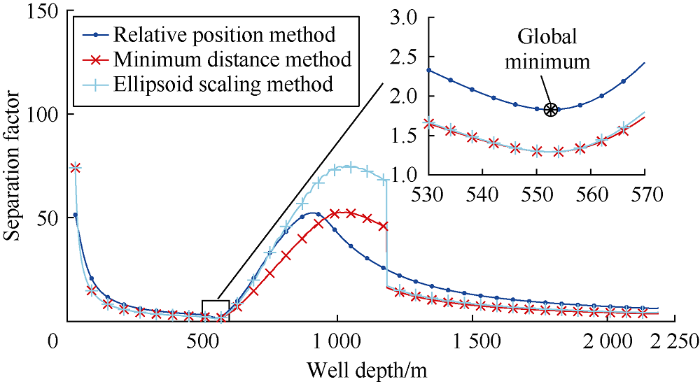
Fig. 5.
Well separation factor between the comparison well B and the reference well.
2.2. Example 2
Here, the influence of location of comparison well B in example 1 on separation factor was studied. The wellhead coordinates of comparison well B relative to the reference well are: the ΔN0 is -15-15 m, ΔE0 is -20-20 m and ΔV0 is 0.09 m. Similarly, MWD was used for trajectory monitoring in the design. The calculation model included 25 terms of error sources[24], and the ellipsoid scale factor was taken as 2.5.
At steps of 0.25 m, 121 points in north-south direction and 161 points in east-west direction were interpolated, so the separation factors of 121×161=19 481 cases of well location were calculated totally. The computing program was written in C++ and run on an ordinary personal computer which had a CPU of Intel Core i7-8700 with the main frequency of 3.0 GHz. It took about 10 min in total to do the computation, and only 30 ms for each case averagely. Clearly, the computation speed was very fast. The chart of the separation factors is shown in Fig. 6.
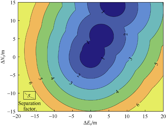
Fig. 6.
Separation factors corresponding to wellhead locations of the comparison well B.
The risk level of well collision has been classified based on the well separation factor abroad and anti-collision codes have been formulated correspondingly[6, 9]. Usually, when Fs>5.0, it is safe to drill, when 1.5<Fs≤5.0, it needs alert and real-time monitoring, when 1.0<Fs≤1.5, it is recommended to close the adjacent well, and when Fs≤1.0, it is required to stop drilling until the danger is eliminated. According to this specification, the well location should be selected in the place with separation factor greater than 5.0, which can be quickly found in Fig. 6.
Using the method presented in this paper for large quantity calculation combined with the anti-collision technical specifications, it is quick and convenient to find the allowable range of key design parameters, not only the wellhead location. It can also be used in well section design and target design, etc. This method is of great value in anti-collision design of trajectories of cluster wells.
3. Conclusions
The relative position method presented in this paper uses the error ellipsoids of the relative position of adjacent wells to calculate the separation coefficient, considers the correlation of the trajectory error of adjacent wells, and improves the theoretical model of well separation factor.
The traditional separation factor found by the distance scanning method of adjacent wells is not necessarily the global minimum. In comparison, the relative position method, which uses the conjugate gradient method to solve the global minimum value, is a more practical, fast and accurate method.
Nomenclature
a, b—lower and upper limits of the search interval, m;
Ak—azimuth angle of the k-th survey point, rad;
B, G, R, S, W—sequence number set of error terms of survey bias, global error, random error, systematical error and well-by-well error;
C(s)—covariance matrix of trajectory error at specified depth;
C(s1,s2)—error covariance matrix of relative trajector;
C1(s1)—covariance matrix of trajectory error of comparison well at depth s1;
C2(s2)—covariance matrix of trajectory error of reference well at depth s2;
Cbias, Cglob, Crand, Csyst, Cwell—covariance matrix of survey bias, global error, random error, systematical error and well-by-well error at specified depth;
d(s1,s2)—coordinate vector of comparison well relative to reference well;
d0—safety allowance for collision avoidance between comparison well and reference well, m;
D1, D2—diameters of the comparison and reference well, m;
Dbias—cross correlation matrix of survey bias between comparison well and reference well;
Dglob—cross correlation matrix of global error between comparison well and reference well;
e—target search error, m;
e1, e2, e3—iterative accuracy;
ei,k—error vector of the i-th error term of the k-th survey point;
ei,k,1, ei,k,2—error vectors of the i-th error term of the k-th survey point on the comparison and reference wells;
f(s1,s2)—separation factor between an investigation points on the comparison well and one on the reference well;
Fs—separation factor between the comparison well and the reference well;
g(s1,s2)—gradient vector of the separation factor derived over depth;
h—differential step size used in Richard extrapolation, usually about 1×10⁻⁶-1×10⁻³ m;
i—serial number of error items;
Ik—inclination angle of the k-th survey point, rad;
j—serial number of secondary survey point;
k—serial number of survey point;
K—serial number of survey point at the end of the survey segment where the investigation point is located;
K1, K2—serial numbers of survey point at the end of the survey segment where the investigation point is located in the comparison well and the reference well;
Lk—well depth of the k-th survey point, m;
ΔLk—length of survey segment between survey point k-1 and survey point k, m;
N, E, V—north, east and vertical coordinates, m;
Nf—rank of Fibonacci series;
N0, E0, V0—north, east and vertical coordinates of wellhead, m;
ΔN0, ΔE0, ΔV0—north, east and vertical coordinates of wellhead of the comparison well relative to wellhead of the reference well, m;
pk—survey data vector of the k-th survey point, pk=[Lk Ik Ak]T;
δpk—survey error vector of the k-th survey point;
${\partial {{\mathbf{p}}_{k}}}/{\partial {{\varepsilon }_{i}}}\;$—weight function of the i-th error term at the k-th survey point, given by the ISCWSA error model;
Pb—confidence probability, which is the probability of wellbore position in the error ellipsoid;
q—coefficient;
r—well radius, m;
r—coordinate vector of the investigation point in trajectory;
δr—error vector of the trajectory at specified depth;
r0—coordinate of the wellhead, r0=[N0E0V0]T;
Δr0—wellhead coordinate vector of the comparison well relative to the reference well, Δr0=[ΔN0 ΔE0 ΔV0]T;
r1, r2—coordinate vectors of the investigation points on the trajectory of the comparison well and the reference well;
rk—coordinate vector of the k-th survey point;
s—the depth of the investigation point on the trajectory, m;
s—vector of search direction;
s1, s2—the depth of the investigation points on the trajectory of the comparison well and the reference well, m;
T—search step size, m;
ui,k—random variable corresponding to the i-th error term of the k-th survey point, which satisfies the Gaussian distribution with the mathematical expectation equal to 0 and the variance equal to 1;
θk—arc angle between survey point k-1 and survey point k, rad;
λ—ellipsoid scale factor;
ξ—relative depth of the investigation point in the survey segment of the trajectory;
ξ1, ξ2—relative depth of the investigation points in the survey segment of the comparison well and the reference well;
σi,k——amplitude of the i-th error term of the k-th survey point, determined by ISCWSA error model;
τk—wellbore axis vector of the k-th survey point.
Reference
Collision avoidance calculations: Current common practice
(
JAMIESON A. Introduction to wellbore positioning: An ISCWSA initiative.
(
Well bore collision avoidance and interceptions: State of the art
Anti-collision risk management standard for well placement
Minimizing the risk of well collisions in land and offshore drilling
Case studies in the application of an effective anticollision risk management standard
Well-collision risk in congested environments
A comprehensive approach to well-collision avoidance
Accuracy prediction for directional measurement while drilling
Towards risk-based well separation rules
Explicit calculation of expansion factors for collision avoidance between two co-planar survey error ellipses
Implementation of a new risk based well collision avoidance method
China offshore anti-collision risk management standard and remedial measures
Calculation method of adjacent well oriented separation factor
Probability analysis of error ellipsoid (ellipse) and hole intersection
An improved method for computing wellbore position uncertainty and its application to collision and target intersection probability analysis
A new calculation method of wellbore separation factor
A calculation method of minimum distance between wellbore survey error ellipsoids
Directional drilling survey calculation methods and terminology: API Bulletin D20
ISCWSA MWD error model revision 4
(
