


Introduction
In the process of drilling and completion of naturally fractured reservoir, leak of working fluid is the most severe way of formation damage and also one of the complex engineering problems which has long impaired drilling efficiency and productivity of oil and gas wells. High temperature, high pressure, high in-situ stress in deep reservoir conditions (buried depth larger than 4500 m) further increase the difficulty of lost circulation control. Moreover, the cost and difficulty to eliminate or alleviate the formation damage induced by working fluid loss through stimulation are also increased. Nowadays, lost circulation control of working fluid in deep naturally fractured reservoir has become a hot and difficult problem in the field of oil and gas well engineering.
To meet the requirements of safe and efficient drilling and formation damage control, scholars have done a lot of research on lost circulation control in low pressure-bearing capacity formation. The temporary plugging method solves the problem of lost circulation control in pore and fracture-pore formations. However, for reservoirs with naturally developed fractures, lost circulation damage is still difficult to be effectively controlled due to the difficulty of lost circulation control[1,2,3,4,5,6]. Researchers have introduced fracture mechanics, granular matter mechanics, catastrophe theory, multiphase fluid mechanics and other related theories to control the lost circulation of working fluid in fractured formation. To date, lost circulation control methods in naturally fractured formation mainly include three kinds: adjusting the stress around the wellbore, plugging the lost circulation channels and improving the strength of rock mass. The methods of adjusting the stress around the wellbore include 3 ways, stress cage, increasing the fracture closing stress and increasing the fracture extension stress. These methods control the lost circulation of working fluid by adjusting the tangential stress field around the wellbore and the stress field at the fracture tip[7,8,9,10,11,12,13,14,15]. Plugging the lost circulation channel refers to building a dense and high-strength plugging zone by using the LCMs to establish the balance between the wellbore fluid column pressure and the formation pressure[16,17,18,19,20,21,22,23,24,25]. Improving rock mass strength method aims to form high-strength structure under the environment of formation temperature, pressure and fluid after the LCMs enter the lost circulation channel, separating the two pressure systems of wellbore and formation[26,27,28,29]. For the method of improving rock mass strength, the plugging zone is usually difficult to be removed, which cannot meet the needs of plugging removal before production, and therefore, it is hardly used in reservoir. For naturally fractured reservoirs, the most commonly used lost circulation control method is to plug the fracture with soluble (acid soluble or oxidation soluble) granular materials[30,31]. The structural stability of fracture plugging zone under high temperature, high pressure and high stress environment is the key to the lost circulation control effect. However, the strength and structure stability of fracture plugging zone in deep naturally fractured reservoir still needs further study.
Based on the granular matter mechanics, the multi-scale structure of fracture plugging zone is defined in the current paper. The structural failure pattern of plugging zone is developed to reveal the plugging zone failure mechanism in high temperature, high pressure and high in-situ stress environment of deep formation. Based on the structural failure mechanism and the mathematical model for fracture plugging zone strength, the key performance parameters are determined for the optimal selection of loss control material (LCM). Laboratory fracture plugging experiments are carried out to evaluate the effect of the key performance parameters of LCMs on fracture plugging quality. LCMs selection strategy for fractured reservoirs is developed.
1. Multiscale structure of fracture plugging zone
As shown in Table 1, the structure stability of fracture plugging zone is of great importance for lost circulation control in fractured formations. Fracture plugging zone is a complex system composed of discrete solid particles, with multis-cale structure (Fig. 1). At the macroscale, the fracture plugging zone is a granular material system formed by LCMs, which can represent the macroscopic mechanical properties of the particle aggregates of LCMs[32]. Under external loading, particles in the plugging zone press against each other, forming contact force. The contact force transfers along the LCMs to form a force chain network, which is the base to support external load. The particle groups or clusters for transferring force chains constitute the mesoscale of the fracture plugging zone. The evolution process of fracture plugging zone pressure structure is also the evolution process of mesoscale force chain network and corresponding particle groups (Fig. 2). At micro-scale, the basic unit of the plugging zone is the single LCM. The performance parameters of LCMs in micro-scale determine the strength of the meso-scale force chain particle group, and in turn the strength and stability of the macro-scale fracture plugging zone. The performance parameters of LCM, including geometric parameters, mechanic parameters and chemical parameters, are important basis for the selection and formula design of LCMs.
Table 1 Control technology of working fluid lost circulation in fractured formation.
| Realization way | Lost circula- tion type | Scope of application | Key points | Schematic diagram | |
|---|---|---|---|---|---|
| Adjusting the stress field around the wellbore | Stress cage | Lost circulation by induced fracture | Formation with underdeveloped fractures Formation with high elastic modulus Isotropic formation | Support the fracture, isolate the crack tip, stability of plugging zone | 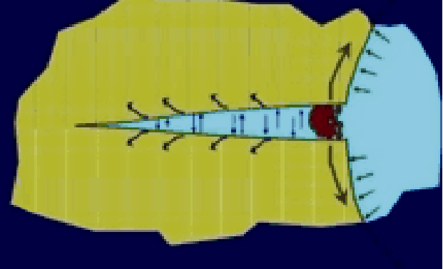 |
| Increase fracture closure stress | Formation with underdeveloped fractures Formation with high elastic modulus Isotropic formation High permeability formation |  | |||
| Increase fracture extension pressure | Lost circulation due to fracture propagation | Formation with naturally developed but not connected fractures | Reduce the pressure in the fracture, Control the stress intensity factor, Stability of fracture-plugging zone | 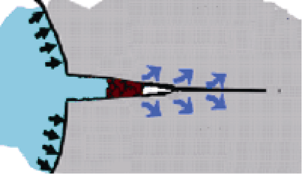 | |
| Plugging the working fluid loss channel | Lost circulation through large and medium fractures | Formation with naturally developed and connected fractures | Formation of plugging zone, Stability of plugging zone | 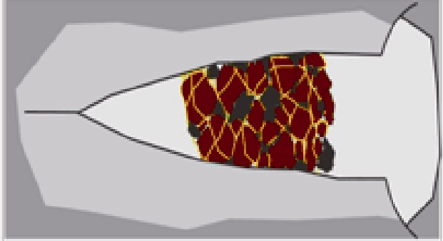 | |
| Increase the strength of rock mass | Rock mass strength, Stability of plugging zone |  | |||
Fig. 1.
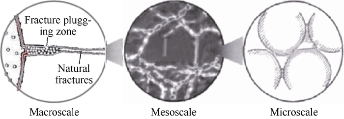
Fig. 1.
Multiscale structure of fracture plugging zone[18].
Fig. 2.
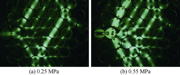
Fig. 2.
Evolution of force chain network of fracture plugging zone under shearing.
2. Structural failure mechanism of fracture plugging zone
2.1. Structural failure patterns
Under the high temperature, high pressure and fluid environments of the formation, the friction force acting on the plugging zone by fracture surface and the plugging zone shear strength are the main factors to maintain the structural stability of fracture plugging zone under wellbore pressure, in-situ stress and formation pressure. According to the mechanical causes of structural failure, plugging zone structural failure can be divided into two patterns: frictional failure and shear failure.
2.1.1. Frictional failure of plugging zone
The friction between the plugging zone and the fracture surface is one of the main factors to keep the plugging zone stable. The reasons cause frictional failure of plugging zone can be divided into three types: global slipping, particle size degradation, and fracture propagation (Fig. 3).
Fig. 3.
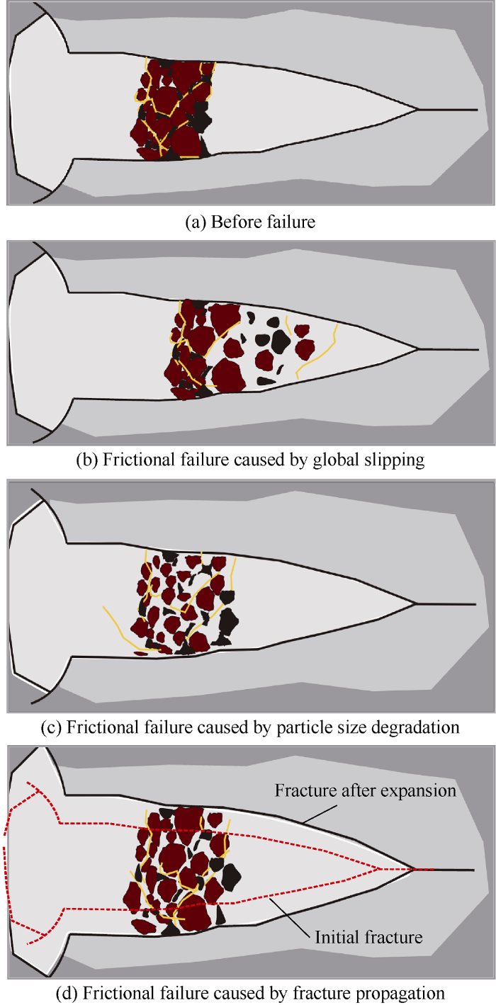
Fig. 3.
Frictional failure patterns of fracture plugging zone.
When the positive pressure difference between wellbore fluid column pressure and formation pressure exceeds the friction between plugging zone and fracture surface, the plugging zone will slide as a whole along the fracture surface, which is called the global slipping frictional failure (Fig. 3b). Under the condition of high temperature and high fracture closure pressure in deep reservoir, the effective stress acting on the plugging zone by the fracture surface can be reduced due to the particle size degradation of the LCMs, which can further reduce the friction between the plugging zone and the fracture surface, finally induce the failure of the plugging zone. This pattern of failure is the frictional failure caused by the particle size degradation (Fig. 3c). If thecompactness of the fracture plugging zone is poor, the wellbore fluid column pressure will be transmitted to the fracture tip through the plugging zone, inducing fracture propagation and extension, thus reducing the effective stress and friction force acting on the plugging zone by the fracture surface. The structural failure of the plugging zone caused by this case is the frictional failure caused by fracture propagation (Fig. 3d).
2.1.2. Shear failure of plugging zone
The shear strength of fracture plugging zone is another main factor to keep the structural stability of plugging zone. Because of the heterogeneity of plugging zone, macroscopic fluctuation of fracture surface and the height change of asperities, the friction between the plugging zone and fracture surface and fracture closure stress in plugging zone aren’t constant[19]. There are low friction and high friction parts between the plugging zone and fracture surface. The part with low friction is the weak point of the fracture plugging zone vulnerable to shear failure under wellbore fluid pressure (Fig. 4). The factors preventing the shear failure of the plugging zone are the shear strength of the force chain on the meso- scale and cohesion and internal friction on macro-scale.
Fig. 4.
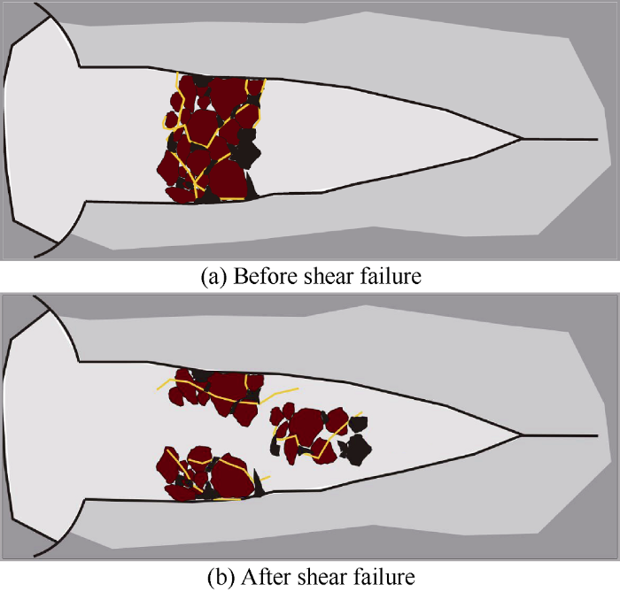
Fig. 4.
Shear failure pattern of fracture plugging zone.
2.1.3. Comprehensive failure of plugging zone
Under the actual operating condition, the structural failure of fracture plugging zone include both frictional failure and shear failure, namely, comprehensive failure. Any of these failure patterns will lead to the plugging zone failure and repeated loss of working fluid. Therefore, the strength of fracture plugging zone ultimately depends on the smaller value in friction strength and shear strength of the plugging zone:
2.2. Strength model of fracture plugging zone
2.2.1. Frictional strength model
When the wellbore fluid column pressure, formation pressure and friction force of fracture surface acting on the plugging zone are in mechanical balance, the fracture plugging zone keeps friction stable. The pressure difference between the critical wellbore fluid column pressure and the formation pressure in case of frictional failure of fracture plugging zone is friction strength of the plugging zone[23]:
2.2.2. Shear strength model
Under the multi-scale structure of fracture plugging zone, the meso-scale force chain strength determines the shear strength of macro plugging zone, and is affected by the performance parameters of micro-scale LCMs. Micro-scale LCMs mainly include granule and fiber materials. The shear strength of the fracture plugging zone is equal to the sum of the shear strengths of particle plugging zone and fiber-reinforced plugging zone:
According to granular matter mechanics, the mesoscale force chain shear strength of plugging zone formed by particles only depends on the contact stress between particles. Therefore, this shear strength of the plugging zone is expressed as[23]:
After the fiber material is added, the shear strength of the fracture plugging zone can be further improved, and the corresponding increment of shear strength is expressed as[23]:
The shear displacement angle of the fiber is expressed as:
3. Extraction of key performance parameters of LCMs
According to the strength model of fracture plugging zone, the LCM geometrical parameters that affect the plugging zone stability under pressure include particle size distribution D90, fiber aspect ratio, fiber initial inclination angle. The LCM mechanical parameters include compressive strength, friction coefficient, fiber elastic modulus and fiber tensile strength. Through the sensitivity analysis of model parameters, the influence of LCM performance parameters on the plugging zone strength is clarified. Accounting for the high temperature, high pressure and high in-situ stress conditions of deep fractured reservoir, the key performance parameters of LCMs are extracted to provide the basis for the optimization and selection of LCMs. The basic parameters for model analysis are shown in Table 2.
Table 2 Basic parameters of the model.
| Parameter | Value | Parameter | Value |
|---|---|---|---|
| Particle size distribution D90 | 0.5 mm | Fiber tensile strength | 35 MPa |
| Fiber aspect ratio | 50 | Fiber concentration | 4% |
| Friction angle of particle surface | 36° | Fracture closure pressure | 10 MPa |
| Friction angle of fiber surface | 24° | Plugging zone porosity | 15% |
| Friction angle between plugg- ing zone and fracture surface | 45° | Plugging zone length | 15 mm |
| Elastic modulus of fiber | 20 MPa | Fracture width | 1 mm |
3.1. Geometrical parameters
3.1.1. Particle size distribution
Particle size distribution is one of the key geometrical parameters of LCMs, which affects the plugging strength and efficiency by affecting the bridging and filling effect of LCMs in the fracture. The D90 of particle size distribution is the main basis for the selection of LCMs and optimization of plugging slurry formula. In addition, the particle size distribution of LCMs impacts the porosity of plugging zone[33]. The porosity of fracture plugging zone reflects the compactness of the plugging zone, and strong force chain can be formed only in the dense particle system. Fig. 5 shows that the fracture plugging zone strength decreases with the increase of plugging zone porosity. By selecting the type, concentration and combination of LCMs, the D90 of particle size distribution can be adjusted, and then the plugging slurry formula can be optimized.
Fig. 5.
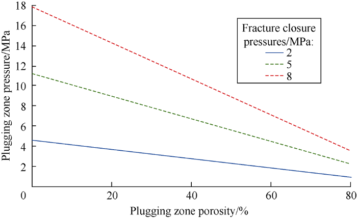
Fig. 5.
Relationship between porosity and plugging zone strength.
3.1.2. Fiber aspect ratio
Fiber aspect ratio is the ratio of fiber length to its diameter. Fig. 6 shows that the fracture plugging zone pressure increases linearly with fiber aspect ratio. The aspect ratio of fiber mainly affects the increment of shear strength of the plugging zone after the fiber is added. The larger the fiber aspect ratio is, the more easily the fiber interweaves into grid structure, the higher the tensile stress of the fiber during the shear deformation of the plugging zone is, and the larger the increment of the shear strength by fiber addition is before fiber tensile failure.
Fig. 6.

Fig. 6.
Relationship between fiber aspect ratio and plugging zone pressure.
3.2. Mechanical parameters
3.2.1. Compressive strength
Because of the high pressure and high in-situ stress condition in deep fractured reservoir, the bridging materials must have high compressive strength to maintain the bridging function of rigid materials continuously. Fracture closure pressure is the pressure acting on plugging zone by fracture surface. On the one hand, the fracture closure pressure affects the friction strength of the plugging zone by affecting the friction force applying on the plugging zone by fracture surface. On the other hand, the fracture closure pressure affects the shear strength of the plugging zone by affecting the friction force applying on the surface of particles and fibers. Fig. 7 shows that both the friction strength and shear strength of plugging zone increase with the increase of fracture closure pressure. Under the parameters shown in Table 2, the friction strength of the plugging zone is always larger than the shear strength of the plugging zone. The plugging zone pressure depends on the smaller one between friction strength and shear strength, so the fracture plugging zone strength is controlled by the shear strength of the plugging zone, and the key to strengthen the maximum plugging zone pressure is to improve its shear strength. The fracture closure pressure is affected by the supporting effect of plugging zone on the fracture surface. The stronger the supporting effect of the plugging zone to the fracture, and the wider the supporting fracture width, the higher the fracture closure pressure will be[7]. Therefore, it is necessary to select rigid particles with high compressive strength to increase the closure pressure of the fracture and the fracture plugging zone strength.
Fig. 7.
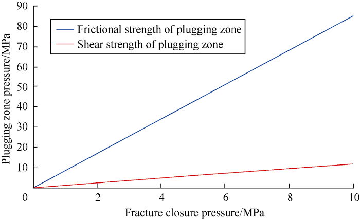
Fig. 7.
Relationship between fracture closure pressure and plugging zone pressure.
3.2.2. Friction coefficient
The friction angle is used to characterize the surface friction coefficient between the particles forming the plugging zone. The friction coefficient is equal to the tangent value of the friction angle. Fig. 8a shows that the plugging zone pressure is positively correlated with the particle-particle friction angle. The particle-particle friction angle mainly affects the shear strength of the plugging zone, and increasing the particle-particle friction angle can enhance the shear strength of the plugging zone. Fig. 8b shows that the fracture plugging zone pressure increases with the increase of particle-fiber friction angle. The particle-fiber friction angle mainly affects the shear strength of the plugging zone, so the shear strength of the plugging zone can be enhanced by increasing the particle-fiber friction angle. The friction angle between plugging zone and fracture surface is used to comprehensively characterize the friction coefficient between LCMs and fracture surface. Fig. 8c shows that the increase of friction angle between plugging zone and fracture surface leads to the increase of friction strength of plugging zone, and in turn increase of the plugging zone pressure.
Fig. 8.
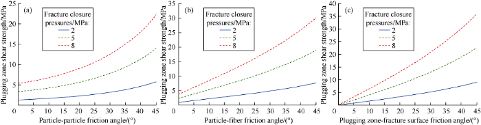
Fig. 8.
Relationship between particle-particle friction angle (a) particle-fiber friction angle (b) friction angle between plugging zone and the fracture surface (c) and plugging zone pressure.
3.3. Chemical parameters
In order to ensure the normal production of deep fracture reservoir, the plugging zone formed in the fracture must be able to be removed in subsequent plugging removal operations such as acidizing etc. Therefore, the LCMs selected should have a certain dissolution rate (acid dissolution or oxidation dissolution).
Walnut shell, cottonseed shell and other organic rigid LCMs are still widely used in deep well to control lost circulation. However, due to the high temperature at the bottom of deep well, the high temperature environment will cause aging and subsequently strength weakening of organic LCMs[34,35,36]. On one hand, high temperature aging makes it easier for the edge of LCMs to erode, the strength of force chain between particles to reduce, and the plugging zone to lose stability. On the other hand, due to high temperature aging, the LCMs in the fracture are more prone to compression failure under the fracture closure pressure. Therefore, the ability of high temperature resistance is one of the key performance parameters of the LCMs used in deep fractured reservoir.
3.4. Key LCM performance parameters
Because the initial angle of the fiber is difficult to control and the elastic modulus of the fiber used for plugging is low, they are not discussed here. The tensile strength of the fiber only affects the plugging zone strength under certain conditions. Therefore, based on the sensitivity analysis results and the conditions of high temperature, high pressure and high in-situ stress in deep naturally fractured reservoir, six key performance parameters of LCMs are finally determined, including particle size distribution D90, fiber aspect ratio, friction coefficient, compressive strength, dissolubility rate and high temperature resistance.
4. Experimental verification of LCM key performance parameters
4.1. Experimental method
To verify the accuracy of the key performance parameters extracted by the model, fracture plugging experiments were carried out on several kinds of new LCMs. The materials included three categories: bridging material, filling material, and reinforcement material. The bridging material included high-strength synthetic polymer material and super irregular shape material. The filling material included rigid particles and elastic particles. The reinforcement material was mainly fiber. The performance parameters of some materials are shown in Table 3. The plugging effect of different LCMs was evaluated by comparing the total loss volume and plugging pressure. The experimental formulas are shown in Table 4. The high-temperature and high-pressure fracture plugging instrument[37] was used for the fracture plugging experiment. The working temperature of the instrument is from room temperature to 200 °C, and the displacement pressure of drilling fluid is 0-30 MPa. The fracture module is 300 mm long and 110 mm high. Two kinds of wedge-shaped fracture modules (3 mm wide at the inlet and 1 mm at the outlet, 8 mm at the inlet and 5 mm at the outlet) were used in the plugging experiment.
Table 3 Performance parameters of some LCMs used in the fracture plugging experiment.
| No. | Initial D90/μm | Friction coefficient | D90 degradation rate after compression/% | D90 degradation rate after aging and compression/% |
|---|---|---|---|---|
| K3 | 7836 | 1.23 | 8.76 | 4.20 |
| K4 | 4207 | 0.95 | 17.66 | 6.50 |
| K5 | 2715 | 1.07 | 17.66 | 4.01 |
| G7 | 3801 | 0.89 | 4.78 | 1.02 |
| G12 | 4797 | 0.66 | 3.84 | 1.14 |
| D2 | 4380 | 0.94 | 4.48 | 1.39 |
| D11 | 1155 | 1.04 | 2.12 | 8.72 |
Table 4 Experimental sample formulation and results of fracture plugging evaluation.
| Num- ber | Formula | Fracture module | Maximum plugging pressure/MPa | Total loss volume/ mL |
|---|---|---|---|---|
| Base drilling fluids | 0# diesel oil (42%-48%) + Main emulsifier (2%-3%) + Auxiliary emulsifier (2%-3%) + Calcium chloride aqueous solution (3.0%-4.5%) + Lime (2.0%-4.5%) + Fluid loss additive (2.0%-2.5%) + Tackifier (0.5%-0.8%) + Suspending agent (0.3%-0.6%) + Fluid flow pattern regulator (0.2%-0.5%) + Wetting agent (0.2%-0.5%) + Anti sloughing agent (1.2%-2.0%) + Weighting agent | Fracture width 0.15 mm | 2.2 | >100 |
| 1-0# | 3% Bridging material K3 + 3% Bridging material K4 + 3% Bridging material K5 + 3% Bridging material G12 + 3% Filling material G7 + 4% Filling material G10 + 3% Filling material D21 + 0.8% Fiber G8 | Fracture width with inlet 8 mm and outlet 5 mm | 7.9 | 250 |
| 1-1# | 5% Bridging material K3 + 3% Bridging material K4 + 3% Bridging material K5 + 3% Bridging material G12 + 3% Filling material G7 + 4% Filling materials G10 + 3% Filling material D21 + 0.8% Fibre G8 | >20.0 | 77 | |
| 2-0# | 3% Bridging material D11 + 3% Filling material G14 + 0.2% Fiber G8 | Fracture width with inlet 3 mm and outlet 1 mm | 9.4 | 19 |
| 2-1# | 3% Bridging material D11 + 3% Filling material G14 + 0.2% Fiber G9 | 11.2 | 9 | |
| 3-0# | 7% Bridging material G7 + 2% Bridging material K3 + 4% Bridging material G4 + 5% Bridging material G6 + 3% Bridging material K4 + 5% Filling material K5 + 10% Filling material G10 + 0.8% Fiber G9 | Fracture width with inlet 8 mm and outlet 5 mm | 5.0 | 130 |
| 3-1# | 4% Bridging material G7 + 5% Bridging material K3 + 4% Bridging material G4 + 5% Bridging material G6 + 3% Bridging material K4 + 5% Filling material K5 + 10% Filling material G10 + 0.8% Fiber G9 | >20.0 | 20 | |
| 4-0# | 6% Bridging material K4 + 5% Bridging material K3 + 3% Bridging material K5 + 3% Filling material G15 + 4% Filling material K6 + 3% filling materials D21 + 0.8% Fiber G8 | Fracture width with inlet 8 mm and outlet 5 mm | 18.0 | 20 |
| 4-1# | 3% Bridging material K4 + 3% Bridging material D2 + 5% Bridging material K3 + 3% Bridging material K5 + 3% Filling material G15 + 4% Filling material K6 + 3% Filling material D21 + 0.8% Fiber G8 | >20.0 | 40 |
4.2. Experimental results and discussion
4.2.1. Particle size distribution of LCMs
The total loss volume of formula 1-0# increased continuously with the increase of displacement pressure. When the displacement pressure reached 7.9 MPa, the fluid loss volume increased rapidly and the plugging zone was destroyed. From the particle size distribution curve of formula 1-0#, it can be seen that the D90 is 5356 μm, and the particle sizes are concentrated from 2400 μm to 5400 μm (Fig. 9). For the fracture module with 8 mm wide inlet and 5 mm wide outlet, the particle size of formula 1-0# is too small. Although it can form plugging zone in the fracture, the plugging zone pressure isn’t high enough. On the basis of formula 1-0#, 2% of the new-type super irregular shape bridging material K3 was added to form formula 1-1#. The formula 1-1# has a particle size distribution D90 of 7814 μm and particle sizes concentrated from 2700 μm to 7800 μm (Fig. 9). The modified formula is more reasonable in particle size distribution. In the fracture with 8 mm wide inlet and 5 mm wide outlet, a tight plugging zone was formed by this formula, with maximum plugging pressure of more than 20.0 MPa, and the total loss volume reducing to 77 mL.
Fig. 9.
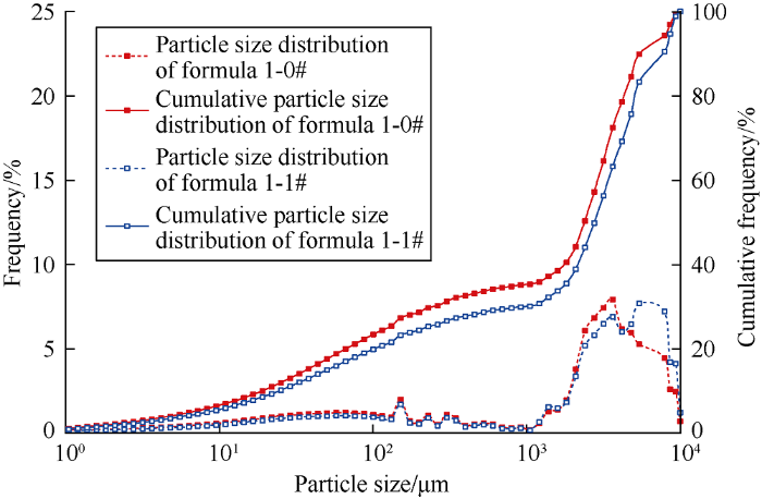
Fig. 9.
Particle size distribution of formula 1-0# and 1-1#.
4.2.2. Fiber aspect ratio
In order to further analyze the influence of fiber aspect ratio on fracture plugging effect, fracture plugging experiments were conducted on formulas with fibers of different aspect ratios. The fiber material G8 (with aspect ratio of 159) in formula 2-0# was replaced by the fiber material G9 (with aspect ratio of 635) to form formula 2-1#. The total dosages of LCMs were the same, and the fibers inside were the same kind with same tensile strength. For formula 2-0#, the fracture plugging zone formed had a maximum plugging pressure of 9.4 MPa and total loss volume of 19 mL (Fig. 10a). For formula 2-1#, the fracture plugging zone formed had a maximum plugging pressure of 11.2 MPa and total loss volume of 9 mL (Fig. 10b). Therefore, the total loss volume can be reduced and the plugging zone pressure can be improved by optimizing the aspect ratio of fiber material.
Fig. 10.
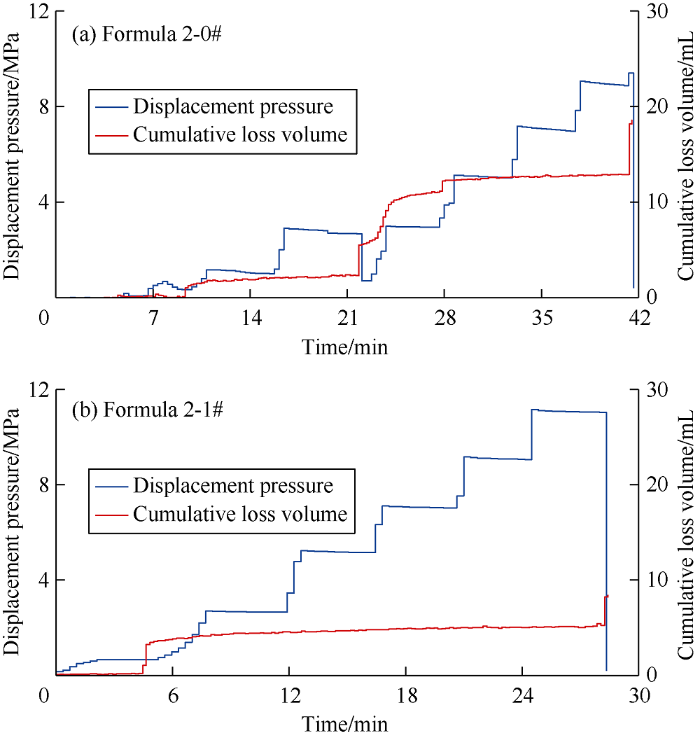
Fig. 10.
Curves of fracture plugging experiments by plugging formulas with different fiber aspect ratios.
4.2.3. Friction coefficient of LCMs
To analyze the influence of friction coefficient of LCMs on the effect of fracture plugging, the bridging materials with different friction coefficient were selected to carry out fracture plugging experiment. The main bridging material G7 in formula 3-0# was replaced by a new-type super irregular shaped bridging material K3 to form formula 3-1#, and the total dosage of LCMs remains the same. The friction coefficient of LCMs was measured by COF-1 friction coefficient system [37]. The surface of G7 was smoother with an average sliding friction coefficient of 0.89, while the surface of K3 was rougher with an average sliding friction coefficient of 1.23 (Fig. 11). For formula 3-0#, the maximum plugging pressure was only 5.0 MPa, and the total loss volume was 130 mL. However, for formula 3-1#, the maximum plugging pressure of the fracture plugging zone was above 20.0 MPa, and the total loss volume was reduced to 20 mL. Therefore, improving the friction coefficient of LCMs can effectively improve the fracture plugging effect.
Fig. 11.
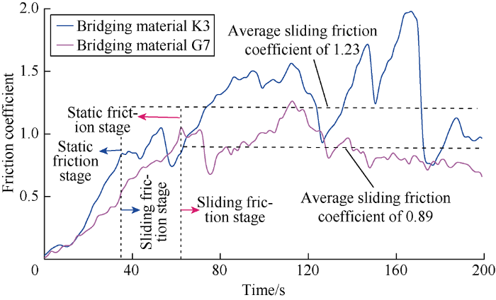
Fig. 11.
Friction coefficient curves of irregular shape bridging material K3 and conventional bridging material G7.
4.2.4. Compressive strength of LCMs
To further analyze the impact of the compressive strength of LCMs on the fracture plugging effect, fracture plugging experiments were carried out on bridging materials with different compressive strengths. The K4 in formula 4-0# was partially replaced by D2 with higher compressive strength to form formula 4-1#, with the total dosage of LCMs remaining the same. The particle size distribution curves of the two materials before and after compression were obtained by a hydraulic press at 25 MPa (Fig. 12), and the compressive strength of the LCMs was evaluated by the change rate of D90. The particle size distribution curve of K4 shifted to right, and its D90 became larger, indicating that the material was flattened and had plastic deformation after compression, which results in the particle size increase in planar view, but particle size decrease in longitudinal view. The D90 change rate of K4 is as high as 17.7%. The D2 is a polymer composite material with high strength, which had a D90 change rate of only 4.5% after compression. For formula 4-0#, the plugging zone formed could bear a maximum pressure of 18.0 MPa. For formula 4-1#, the plugging zone formed could bear a maximum pressure of greater than 20.0 MPa.
Fig. 12.
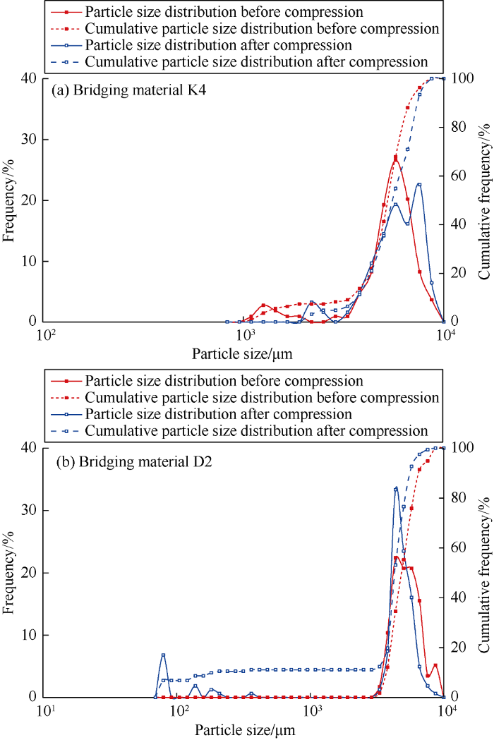
Fig. 12.
Particle size distribution curves of K4 and D2 before and after compression.
5. Methods for strengthening structure stability of fracture plugging zone
Forming high quality plugging zone is the key to control lost circulation in deep naturally fractured reservoir. The key to strengthen the structure stability of plugging zone is the selection of LCMs. According to the failure mechanisms of fracture plugging zone, the selection principle of LCMs is proposed (Fig. 13).
Fig. 13.
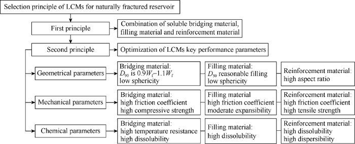
Fig. 13.
Selection principle of LCMs for naturally fractured reservoirs.
The first principle is to optimize the type of LCMs, and to form a plugging zone with high strength by making use of the synergistic effect of soluble bridging material, filling material and reinforcement material. The second principle is to optimize the key performance parameters of the LCMs, including the bridging material, filling material and reinforcement material, so as to further improve the structure stability of the plugging zone. In the second principle, the key performance parameters of LCMs include three categories: geometrical, mechanical and chemical parameters. Among them, the optimization of geometrical parameters is mainly achieved by optimizing the particle size distribution and geometry of LCMs. The key to the optimization of geometrical parameters is to improve the plugging efficiency of LCMs for fractures, which requires the granular LCMs to bridge quickly and stably, and fill efficiently and compactly. The bridging material constitutes the main framework of the fracture plugging zone, and the optimization principle of D90 particle size distribution is the main method of selecting bridging material for fractures with millimeter width[21], that is, the D90 of the LCMs is greater than or equal to 5/6 times of the fracture width. Due to the particle size degradation of rigid plugging materials in deep wells during drilling fluid circulation, the D90 can be appropriately enlarged. In order to improve the retention efficiency of bridging materials in fractures, the bridging materials with low sphericity can be selected. In addition to particle size distribution, the key performance parameters of LCM also include fiber aspect ratio, friction coefficient, compressive strength, dissolubility rate and high temperature resistance. The corresponding evaluation indexes are shown in Table 5. The friction coefficient can be tested by making the LCM into friction plate. The degradation rate of D90 under 25 MPa is used to evaluate the compressive strength and temperature resistance of the material, and the degradation rate of D90 after high temperature aging is used to evaluate the LCM temperature resistance. The temperature resistance value takes the lower value between temperature resistance of particle size and temperature resistance of strength.
Table 5 Evaluation indexes of key performance parameters of LCMs.
| Grade | friction coefficient | Fiber aspect ratio | Dissolubility rate/% | D90 degradation rate at 25 MPa (evaluation of compressive strength and temperature resistance of strength)/% | Degradation rate of D90 after high temperature aging (evaluation of temperature resistance of particle size)/% |
|---|---|---|---|---|---|
| Low | <0.5 | <30 | <20 | >30 | >30 |
| Medium to low | 0.5-0.8 | 30-100 | 20-40 | 20-30 | 20-30 |
| Medium | 0.8-1.1 | 100-200 | 40-60 | 10-20 | 10-20 |
| Medium to high | 1.1-1.4 | 200-500 | 60-80 | 5-10 | 5-10 |
| High | >1.4 | >500 | >80 | <5 | <5 |
Well D1201 is an evaluation well deployed in Kuqa depression of Tarim Basin. The section of 5500-5510 m is a salt gypsum layer with thickness of hundreds to kilometers. The interbed lithology is mudstone and dolomite with developed fractures. The formation under salt is mudstone and sandy conglomerate developed with microfractures. When salt gypsum layer is drilled, the lost circulation is frequent. In the early stage, 20 times of plugging while drilling and 4 times of special plugging are conducted to control lost circulation based on traditional trial-and-error method. The lost circulation problems are not effectively controlled. According to the selection principle of LCMs in this paper, the LCMs are systematically evaluated from the aspects of particle size distribution, fiber aspect ratio, friction coefficient, compression resistance, high temperature resistance, etc. A series of LCMs suitable for the salt gypsum layer in the front of Kuqa Piedmont structure are optimized, and a strong retention and high maximum plugging pressure plugging formula is formulated, which successfully controlled the lost circulation of well D1201. After lost circulation operation, the density of drilling fluid increased from 1.71 g/cm3 to 1.76 g/cm3 without lost circulation during normal circulation.
6. Conclusions
The multiscale structure of fracture plugging zone is composed of three dimensions: single LCM, force chain particles cluster, and plugging zone in the fracture. The strength of mesoscale force chain depends on the performance parameters of microscale LCMs and determines the strength and stability of macroscale plugging zone.
Frictional failure and shear failure are the main failure patterns of fracture plugging zone. The friction force applied by fracture surface on the plugging zone and the shear strength of the plugging zone are the main factors which maintain the plugging zone structure stability under high temperature, high in-situ stress and high fluid pressure conditions.
Forming high quality plugging zone is the key for lost circulation control in deep fractured reservoir. Its strength and structure stability depend on the optimal selection of LCMs. D90 value of particle size distribution, fiber aspect ratio, friction coefficient, compressive strength, soluble ability and high temperature resistance are the key performance parameters for LCM optimal selection in deep naturally fractured reservoirs.
Nomenclature
a—length of plugging zone, m;
A—total cross-sectional area of plugging zone, m2;
Af—total cross-sectional area of fibers in plugging zone, m2;
df—fiber diameter, m;
dp—average particle diameter, m;
D50,D90—the value of the particle diameter at 50% and 90% in the cumulative size distribution curve, m;
Ef—elastic modulus of fiber, Pa;
kp—stiffness of granular material, N/m;
lf—length of fiber, m;
pc—fracture closure pressure, Pa;
pz—plugging zone pressure, Pa;
pzf—frictional strength of plugging zone, Pa;
pzs—shear strength of plugging zone, Pa;
pzsf—plugging zone shear strength increment because of fiber addition, Pa;
pzsp—shear strength of plugging zone formed with particles, Pa;
Wf—fracture width, m;
δ1—friction angle between particle and particle, (°) ;
δ2—friction angle between fiber and fiber, (°) ;
δ3—friction angle between plugging zone and fracture surface, (°) ;
ΔH—height of the shear failure part in the fracture plugging zone, m;
εp—particle contact deformation, m;
θ—shear displacement angle of fiber, (°);
θi—initial inclination of fiber, (°) ;
f—porosity of plugging zone, %.
Reference
Mud design to minimize rock impairment due to particle invasion
Research on the application of temporary and shielding plugging technology in reservoir protection
New optimized design method and application of drilling fluid used for formation damage control
Study on system of broad-spectrum temporary blocking drilling and completion fluid for reservoir protection
Study on membrane generating technology of water based drilling fluid
Temporary sealing technology to control formation damage induced by drill-in fluid loss in fractured tight gas reservoir
DOI:10.1016/j.jngse.2014.06.016 URL [Cited within: 1]
Drilling fluid for wellbore strengthening
Best practice in understanding and managing lost circulation challenges
Method to eliminate lost returns and build integrity continuously with high-filtration-rate fluid
Use of new hydrostatic packer concept to manage lost returns, well control, and cement placement in field operations
Rock-property changes during reservoir compaction
DOI:10.2118/13099-PA URL [Cited within: 1]
Experimental and mechanistic modeling of fracture sealing resistance with respect to fluid and fracture properties: Proceedings of the 45th US Rock Mechanics Geomechanics Symposium
Plugging mechanism of drilling fluid by enhancing wellbore pressure
Obtaining both horizontal stresses from wellbore collapse
Plugging mechanism of estimation model of rigid particles while drilling in fractured formation
Comprehensive evaluation of formation damage induced by working fluid loss in fractured tight gas reservoir
DOI:10.1016/j.jngse.2014.03.016 URL [Cited within: 1]
Constructing a tough shield around the wellbore: Theory and method for lost-circulation control
Drill-in fluid loss mechanisms in brittle gas shale: A case study in the Longmaxi Formation, Sichuan Basin, China
DOI:10.1016/j.petrol.2018.11.026 URL [Cited within: 2]
Tight fracture-plugging mechanism and optimized design for plugging drilling fluid
Updated criterion to select particle size distribution of lost circulation materials for an effective fracture sealing
DOI:10.1016/j.petrol.2016.10.027 URL [Cited within: 2]
Modeling lost circulation through drilling-induced fractures
DOI:10.2118/187945-PA URL [Cited within: 1]
Lost-circulation control for formation-damage prevention in naturally fractured reservoir: Mathematical model and experimental study
DOI:10.2118/182266-PA URL [Cited within: 4]
Analytical model of plugging zone strength for drill-in fluid loss control and formation damage prevention in fractured tight reservoir
DOI:10.1016/j.petrol.2016.10.069 URL [Cited within: 1]
Stochastic modelling of particulate suspension transport for formation damage prediction in fractured tight reservoir
DOI:10.1016/j.fuel.2018.02.056 URL [Cited within: 1]
The mechanism for fuzzy-ball working fluids for controlling & killing lost circulation
DOI:10.1007/s11434-010-3091-x URL [Cited within: 1]
Lost circulation control in fractured formations
Study of plugging mechanism and technology of separating-type gel slug
Impact resistance of special gel for drilling plugging
Prevention of fracture propagation to control drill-in fluid loss in fractured tight gas reservoir
DOI:10.1016/j.jngse.2014.08.021 URL [Cited within: 1]
The multiscale structure of dense granular matter
Loss control material for fractured-vuggy carbonate reservoirs of high temperature and pressure in Tazhong block, Tarim Basin, NW China
High-temperature aging property evaluation of lost circulation materials in deep and ultra-deep well drilling
Mechanics of fiber reinforcement in sand
DOI:10.1016/j.heliyon.2020.e03755
URL
PMID:32322731
[Cited within: 1]

The study of the fiber-matrix interface represents a crucial topic to determine the mechanical performance of geopolymer-based materials reinforced with polypropylene fibers (PPF). This research proposes the use of natural zeolite in the preparation geopolymers mortars through alkaline activation with NaOH, Ca(OH)2 and Na2SiO3, and with river sand as a fine aggregate. PPF were incorporated into the geopolymer-based mortar matrix in different proportions like 0, 0.5, and 1 wt.%. The mortars were cured for 24 h at 60 °C and then aged for six days more at room temperature. All samples analyzed through compressive strength were also characterized by X-ray diffraction, thermal analysis, Infrared Spectroscopy, and scanning electron microscopy techniques. The results indicated that the best mix design among the ones used: NaOH (10 M), Na2SiO3/NaOH = 3, Ca(OH)2 = 1.5 wt.% and PPF = 0.5 wt.%. The optimum mix design showed a compressive strength of 4.63 MPa on average. Besides, the fibers enhanced the compressive strength of those samples which the PP fibers probably have better dispersion inside the matrix of the geopolymer mortar.
Friction coefficient: A significant parameter for lost circulation control and material selection in naturally fractured reservoir
DOI:10.1016/j.energy.2019.03.017 URL [Cited within: 2]
